Article

Untreated vs. Treated Carbon Felt Anodes: Impacts on Power Generation in Microbial Fuel Cells

1
Univ Lyon, Ecole Centrale de Lyon, INSA Lyon, Université Claude Bernard Lyon 1, CNRS, Ampère, UMR5005, 69130 Ecully, France
2
Chemical Analysis and Biosensors Group, Laboratory of Process Engineering and Environment, Faculty of Science and Techniques, Hassan II University of Casablanca, B.P 146, Mohammedia 20000, Morocco
*
Author to whom correspondence should be addressed.
Micromachines 2023, 14(12), 2142; https://doi.org/10.3390/mi14122142
Submission received: 19 October 2023 / Revised: 19 November 2023 / Accepted: 20 November 2023 / Published: 23 November 2023

Abstract

:
This research sought to enhance the efficiency and biocompatibility of anodes in bioelectrochemical systems (BESs) such as microbial fuel cells (MFCs), with an aim toward large-scale, real-world applications. The study focused on the effects of acid-heat treatment and chemical modification of three-dimensional porous pristine carbon felt (CF) on power generation. Different treatments were applied to the pristine CF, including coating with carbon nanofibers (CNFs) dispersed using dodecylbenzene sulfonate (SDBS) surfactant and biopolymer chitosan (CS). These processes were expected to improve the hydrophilicity, reduce the internal resistance, and increase the electrochemically active surface area of CF anodes. A high-resolution scanning electron microscopy (HR-SEM) analysis confirmed successful CNF coating. An electrochemical analysis showed improved conductivity and charge transfer toward [Fe(CN)6]3−/4− redox probe with treated anodes. When used in an air cathode single-chamber MFC system, the untreated CF facilitated quicker electroactive biofilm growth and reached a maximum power output density of 3.4 W m−2, with an open-circuit potential of 550 mV. Despite a reduction in charge transfer resistance (Rct) with the treated CF anodes, the power densities remained unchanged. These results suggest that untreated CF anodes could be most promising for enhancing power output in BESs, offering a cost-effective solution for large-scale MFC applications.

1. Introduction

Microbial fuel cells (MFCs) have emerged as a promising technology for the direct conversion of chemical energy from organic substrates into electricity, leveraging the catalytic activity of electrochemically active bacteria (EAB) at the anode [1,2,3,4]. The electrons released during substrate oxidation at the anode are transferred to the cathode, typically via an oxygen reduction reaction. Despite the potential of MFCs for wastewater treatment and power generation, their real-world application remains limited due to challenges such as low power densities [5,6]. One of the primary factors influencing MFC performance is the efficiency of extracellular electron transfer (EET) at the anode, which is determined by the properties of the anode material [7]. Among the myriad of materials explored, carbon felt (CF) has emerged as a frontrunner. Its inherent biocompatibility, electrical conductivity, and 3D porous structure make it an ideal candidate for facilitating efficient EET in BESs [8,9,10,11]. However, while CF is a frontrunner among multiple materials explored, there is a growing consensus that its performance can be further enhanced through strategic functionalization and modification [8,10,11]. Recent studies have delved into the acid-heat treatment of CF to optimize its properties for MFC applications. Such treatments have been shown to modify the surface structure and chemistry of the carbon felt, leading to enhanced bioelectricity generation. For instance, a study by Simeon et al. highlighted the combined effects of electrode material, spacing, and substrate feeding frequency on MFC performance [12]. Another study by Miran et al. emphasized the role of iron oxide-modified carbon electrodes in tandem with sulfate-reducing bacteria for efficient bio-electricity generation [13]. Fatima and colleagues integrated a novel lignin-based carbon fiber felt bioanode in an MFC, demonstrating its potential for treating recalcitrant textile wastewater [14]. Additionally, Kim et al. employed microwave and sulfuric acid treatments on graphite granules, resulting in a significant boost in bioelectricity generation in MFCs [15]. Furthermore, recent advancements in electrode functionalization have highlighted the potential of carbon nanofibers (CNFs) to enhance the electrochemical and catalytic properties of electrodes [16,17]. For instance, the use of Mo-doped carbon nanofibers (Mo-CNFs) as an anode in MFCs, as demonstrated by Wu et al., resulted in a power density that was double that of electrodes with unmodified CNFs [18]. Such advancements highlighted the pivotal role of CNF-functionalized electrodes in optimizing MFC performance. The dispersion of CNFs using surfactants like dodecylbenzene sulfonate (SDBS) and biopolymers such as chitosan (CS) has been shown to further enhance the hydrophilicity, biocompatibility, and electrochemical properties of the anode, paving the way for more efficient and robust MFC systems [19,20,21]. Such functionalization techniques have been shown to promote a better dispersion of CNFs on the electrode surface, leading to improved electrochemical activity and stability [22]. The use of SDBS as an anionic surfactant has been particularly effective in achieving stable aqueous dispersions of CNFs, with the π-π stacking induced by the benzene ring in SDBS playing an important role in this stabilization [23]. Furthermore, the functionalization of electrode surfaces using CNFs dispersed with CS biopolymer has been identified as a promising strategy to augment their electrochemical and catalytic attributes. For example, Liu et al. (2018) presented a CNFs/CS nanocomposite as a biocompatible electrode material, which enhanced the electricity generation in microbial fuel cells [24]. Similarly, Plekhanova et al. proposed an innovative technique for the immobilization of bacterial cells on graphite anode surfaces using CNFs combined with CS [25]. This modification led to a notable improvement in MFC performance. While these modification processes can enhance performance, they also elevate the cost of electrodes, potentially hindering the mass production of anodes. As a result, the feasibility of implementing large-scale MFC technology with nanomaterial-modified anodes is still being explored. A recent study by Fonseca et al. highlighted that an MFC equipped solely with pristine CF achieved a maximum power density (Pmax) of 1.46 W m−2, surpassing many results from studies using modified anodes [8]. This suggests that utilizing unmodified electrodes could be beneficial for the widespread, real-world application of MFCs.
In light of these considerations, this study undertakes a thorough examination of the performance dynamics of pristine CF anodes in MFCs in comparison to their modified counterparts. Through a systematic evaluation of various treatments and modifications, this work seeks to glean insights into the ideal anode material for MFCs. The ultimate objective is to harmonize performance enhancement with cost-effectiveness, potentially facilitating the wider adoption of MFC technology across various applications [26,27]. In this investigation, multiple treatments were administered to assess their influence on the performance of CF-based anodes in MFCs. The anodes were subjected to six distinct conditions, encompassing both pristine CF (CF) and acid-heat-treated CF (A-CF) substrates. These were subsequently immersed in two separate aqueous dispersions of CNFs, dispersed using either the SDBS surfactant (CF@CNF-SDBS, A-CF@CNF-SDBS) or the CS biopolymer (CF@CNF-CS, A-CF@CNF-CS). High-resolution scanning electron microscopy (HR-SEM) was employed to analyze the surface morphology of all anode materials. Electron transfer dynamics across these anode surfaces were probed using cyclic voltammetry (CV) and electrochemical impedance spectroscopy (EIS). The electrochemical characterization and performance of MFCs, equipped with different anodes, were examined and compared using single-chamber bottle-type MFC in batch mode. The electrochemical behavior and extracellular electron transfer were assessed using CV in MFC reactors at biofilm maturation.

2. Materials and Methods

2.1. Chemicals and Materials

Sulfuric acid (H2SO4, 95.0–98.0%), sodium dodecylbenzene sulfonate (SDBS), chitosan (CS), carbon nanofibers (CNF, pyrolytically stripped, platelets (conical), >98% carbon basis, D × L 100 nm × 20–200 µm), agarose, KCl, Nafion (5 wt.%), platinum on carbon black (10 wt.% Pt/C), sodium acetate (NaAc), and 2-propanol (≥99.5%) were sourced from Sigma-Aldrich (France) and utilized without further purification. A polytetrafluoroethylene (PTFE) spray solution (3 in 1) was procured from Castorama (Dardilly, France). All other reagents employed in this study were of analytical grade. Primary wastewater effluent (7 mS cm−2), serving as an electrolyte, and anaerobic activated sludge, used as a source of electrochemically active bacteria (EAB) in a NaAc (10 mM) medium, were collected from the Grand Lyon domestic wastewater treatment plant (Lyon, France). These were utilized for the initiation of single-chamber bottle-type microbial fuel cells (Figure S1) operated in batch mode.

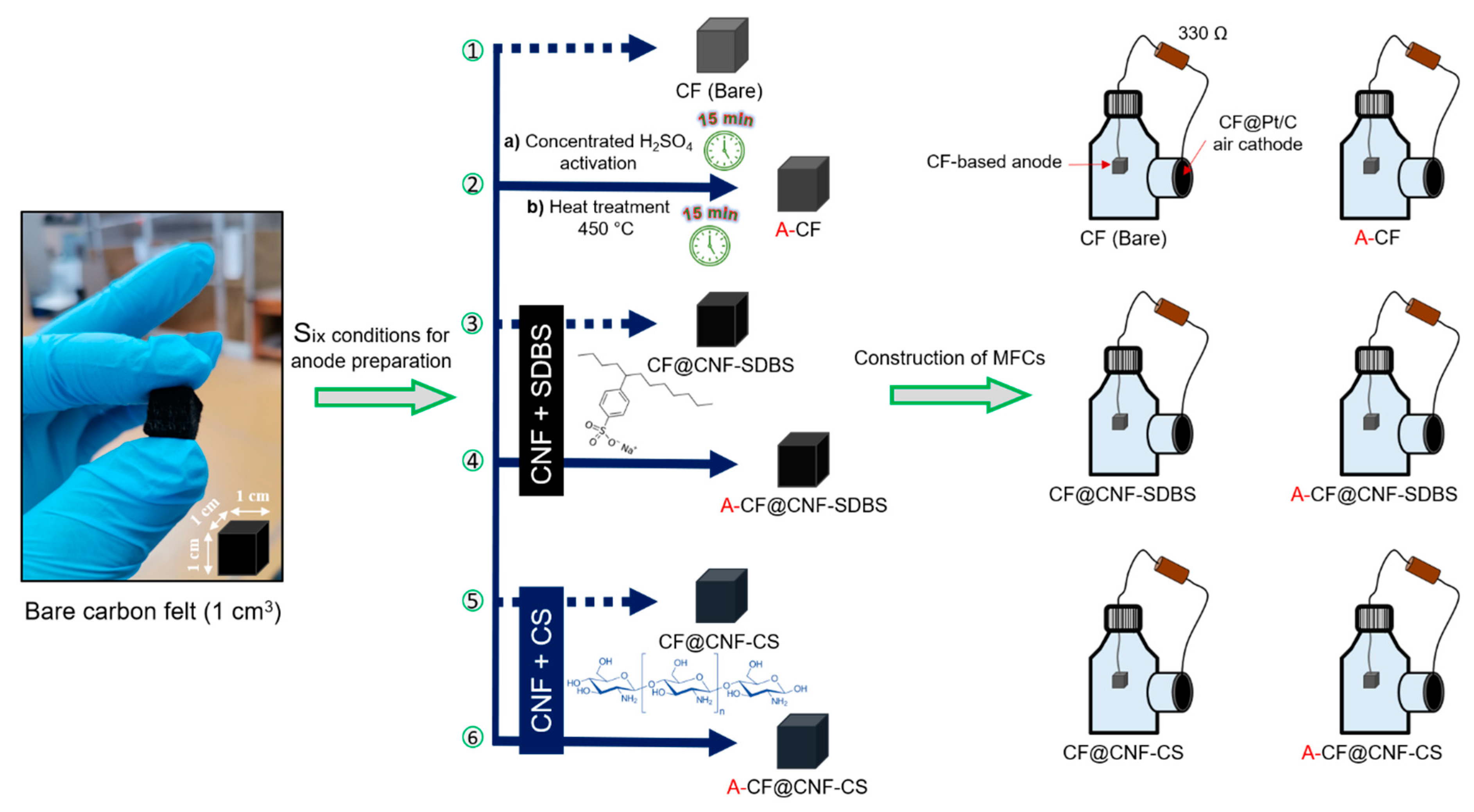
2.2. Pretreatment and Modification of Carbon Felt-Based Anodes

As depicted in Figure 1, a series of six anodes were fabricated through acid activation, heat treatment, and immersion in CNF dispersions of CF anodes. The anode substrates, both pristine CF and A-CF, were individually immersed in two CNF dispersions utilizing SDBS surfactant and CS as dispersing agents. Initially, the pristine CF underwent sequential pretreatment with three distinct solvents (ethanol, acetone, and water), each subjected to 15 min of ultrasonication (Figure 1A). Following a drying period at 60 °C for 3 h, the CF was sectioned into 1 × 1 × 1 cm3 cubes and immersed in concentrated H2SO4 for 15 min under agitation. After multiple water rinses to achieve a neutral pH, the CF anodes were dried at 60 °C for another 3 h. The acid-treated CF electrodes then underwent a heat treatment at 450 °C for 15 min in a muffle furnace to remove manufacturing impurities [19,28]. This acid and heat treatment process aimed to diminish the internal resistance of CF, enhance hydrophilicity, and foster the creation of functional group-rich CF surfaces, potentially promoting superior adhesion of electroactive biofilms [20]. To further optimize the internal resistance and conductivity of both pristine (CF) and activated CF (A-CF), a chemical modification was undertaken (Figure 1B). This modification, designed to enhance interactions between electrogenic bacteria and the anode surface, involved the preparation of electrically conductive CNF dispersions. CF and A-CF were coated with CNF through a straightforward immersion and drying procedure. Aqueous CNF dispersions (2 mg mL−1) were prepared by ultrasonically treating CNFs in two distinct solutions of dispersing agents (SDBS surfactant and CS biopolymer) for 2 h. Both SDBS and CS solutions were prepared at concentrations of 2 mg mL−1 in water and 1% (v/v) acetic acid, respectively. These agents ensured stable and efficient CNF dispersion. The immersion and drying steps were repeated thrice to augment CNF loading and reduce the internal resistance of either pristine CF or A-CF. In the final step, all fabricated anodes were connected to the external circuit using stainless steel wire. Before MFC assembling and operations, the electrochemical activities of the prepared CF anodes were evaluated using CV and EIS techniques in 0.1 M KCl solution containing 10 mM [Fe(CN)6]3−/4− redox probe. This is to evaluate and characterize the electron transfer at the surface of the synthesized anode materials. The redox probe and KCl were prepared in ultrapure water (18.2 MΩ cm−2). These anodes were then ready for characterization and deployment in MFC reactors.

2.3. Fabrication of Reference Electrodes

Due to the limitations of commercial Ag/AgCl reference electrodes (REs) in terms of size, a cost-effective, miniaturized Ag/AgCl (saturated KCl) RE was fabricated. The fabrication process was executed in three distinct phases. (i) Ag/AgCl formation: Silver wires were partially immersed in a 50 mM FeCl3·6H2O solution for a duration of 1 min (Figure S2). This immersion facilitated the formation of an AgCl film on the silver wires, in accordance with the specified redox reactions [28]. Subsequently, the silver wires, now coated with the AgCl film, were transferred to a saturated KCl solution. (ii) Preparation of ion-conducting agarose hydrogel: This phase involved the creation of a conductive hydrogel to act as a salt bridge at one end of a Pasteur pipette. The hydrogel was formulated by dispersing 1% (w/v) agarose in a saturated KCl solution (0.2 g in 20 mL). This mixture was subjected to microwave irradiation for a total of 1 min (in two 30-s intervals) to ensure complete agarose dispersion. The resultant dispersion was then placed on a preheated hotplate set at 80 °C and stirred vigorously. Concurrently, aliquots of the solubilized agarose solution were injected into one end of Pasteur pipettes and subsequently cooled in a saturated KCl solution. (iii) Assembly of the reference electrode: Once the hydrogel solidified, the pipettes were filled with saturated KCl. The previously prepared Ag/AgCl electrodes were then inserted, yielding Ag/AgCl (saturated KCl) REs analogous to commercial variants (Figure S3). The opposite ends of the Pasteur pipettes were sealed using silicone and left to dry at room temperature prior to their deployment in MFC systems. The potential of these home-made reference electrodes was measured against commercial AgCl/Ag reference electrodes, and only those electrodes exhibiting a shift of less than 10 mV were retained. This potential difference was noted for each electrode and considered to adjust the potential values presented.

2.4. MFCs Configuration, Inoculation, and Operation

Single-chamber batch MFCs were set up using 250 mL Wheaton bottles in the laboratory at ambient temperature. The cathode was prepared with a PTFE coating and a 5% platinum catalyst, following the procedure outlined by Cheng et al. [21]. The fabricated electrodes, encompassing cathodes, anodes, and reference electrodes, were integrated into single-chamber MFCs, as depicted in Figure 2. Each MFC system incorporated an anode material in the form of a 1 × 1 × 1 cm3 CF substrate cube. The MFC chambers were filled with 250 mL of primary effluent (7 mS cm−2), supplemented with 5 g L−1 of activated anaerobic sludge sourced from the Grand Lyon municipal wastewater treatment plant (Lyon, France), and enriched with NaAc (1 g L−1) medium to serve as a carbon substrate. Throughout the MFC operation, the cathode and anode in each reactor were interconnected through an external circuit, bridged by a 330 Ω resistor. This setup facilitated the formation of an electroactive biofilm on the anode surface and enabled electron transfer from the anode to the cathode. The spatial separation between the anode and cathode was maintained at approximately 2 cm. Additionally, all single-chamber MFCs were interfaced with data acquisition systems to continuously monitor and record voltage output during the maturation of the anodic biofilm every 1 min with a precision of 1 µV (Figure S4).

2.5. Electrochemical and SEM Characterization

The electrochemical characterization of the anode surfaces was achieved at ambient temperature using CV and EIS techniques within a conventional three-electrode electrochemical cell system, interfaced with a potentiostat (OGS 500, Origalys, Rilleux-La-Pape, France). These electrochemical measurements were designed to assess electron transfer mechanisms. As depicted in Figure S5, the three-electrode assembly consisted of uncoated or CNF-coated CF electrodes as working electrodes (WE), a stainless steel rod as a counter electrode (CE), and a commercially available Ag/AgCl electrode as a reference electrode (RE). The electrolyte used was a 0.1 M KCl solution containing a 10 mM [Fe(CN)6]3−/4− redox probe. The CV measurements were conducted in the fixed potential range of −1 V to +1 V (vs. Ag/AgCl) at a scan rate of 100 mV s−1. EIS was carried out in the frequency range of 100 kHz to 10 mHz at the open circuit potential (OCP) with 10 mV s−1 amplitude. Upon stabilization of the voltage output (indicative of biofilm maturation) as recorded by data logging systems, the external circuit was opened and then reconnected with a potentiostat in a two-electrode arrangement. Then, each anode electrode of the MFCs was connected as WE, while the air cathode was connected to the potentiostat’s two shorted RE and CE cables. Afterward, the polarization curves (V-I) of the six different anodes were recorded using linear seep voltammetry (LSV) over a potential range from OCP values to 0 V at a scan rate of 10 mV s−1. Moreover, the power density (P, W m−2) curves were obtained by multiplying the cell voltage by current density (J, A m−2) according to Equation (1).
P = V × I / S
where V represents the measured voltage and I denotes the current normalized to the projected anode surface area (S). On the other hand, the anodic biofilm formed at the six anodes was characterized using CV, which might provide information including the electrochemical activity and electroactive species involved in charge transfer. Indeed, the electroactivity of anodic biofilms or the load in electrochemically active bacteria (EAB) could be assessed as a function of the current intensities related to its typical redox peaks in CV [29]. The CV curves at biofilm maturation were recorded in the potential range of −800 mV to 700 mV (vs. Ag/AgCl) at a scan rate of 10 mV s−1 in MFC reactors containing wastewater and 10 mM NaAc substrate. Furthermore, the surface morphology of all prepared anode materials based on CF substrates was investigated using field emission scanning electron microscopy (SEM) (SEM TESCAN model MIRA-3 (TESCAN-ORSAY, Brno, Czech Republic)).

3. Results and Discussion

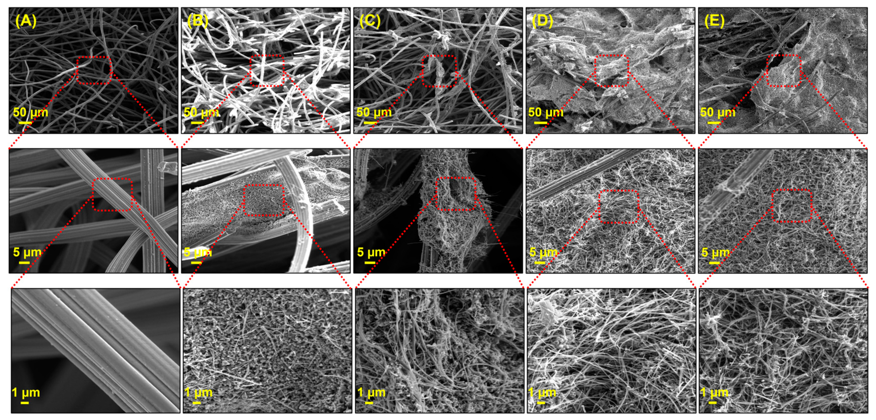
3.1. Surface Morphology of CF Electrodes

After the successful preparation of uncoated and CNF-coated CF anodes, an SEM analysis was performed to examine the surface morphology before and after modification of all prepared anodes, as shown in Figure 3. As can be seen, the pristine CF anode was made up of carbon fibers with a diameter of approximately 10 µm, which networked and formed a 3D macroporous structure. Furthermore, the carbon fibers of the pristine CF have a smooth surface. Figure 3B and Figure 3C demonstrate that the pristine CF and A-CF were successfully coated with CNF dispersed in a CS solution (i.e., the carbon fibers were covered by the CNF-CS composite), respectively. Similarly, CNF dispersed in an SDBS surfactant solution coated the total volume of both CF and A-CF anode substrates, as shown in Figure 3D and Figure 3E, respectively. The CNF was embedded in the 3D macroporous structure. A notable increase in the roughness of individual carbon fibers is evident post CNF coating, suggesting a potential enhancement in specific surface area without compromising the structural integrity of the fibers. As observed in Figure 3B,C, the CNF-CS particles tend to agglomerate, resulting in the formation of grain-like structures. In contrast, the CNF-SDBS composites, as seen in Figure 3D,E, manifest a distinct mesh-like network within a 3D microstructure. These results provided a detailed insight into the surface morphology of both uncoated and CNF-coated CF anodes. The distinct structural differences between the pristine CF and the CNF-coated versions, whether dispersed in CS or SDBS, underscore the potential for tailored surface properties. Such modifications, especially the increased roughness and specific surface area, could play a main role in enhancing the electrochemical performance of the electrodes. To elucidate the rationale behind the distinct microstructures observed in Figure 3, it is essential to understand the interaction dynamics between the coating materials and the CF substrate. The CNF-CS composite leads to grain-like structures due to the adhesive and film-forming properties of chitosan. This results in a more pronounced agglomeration of CNF particles, enhancing the surface roughness and potentially the bioactivity of the anode. In contrast, the CNF-SDBS dispersion creates a mesh-like network within the CF’s 3D microstructure. The surfactant properties of SDBS facilitate a more uniform CNF dispersion, preventing particle aggregation and ensuring a more intricate and evenly distributed coating. This microstructure variation is significant for electrochemical applications, as it directly impacts the surface area and the electrode’s biofilm-interaction capabilities. These observations underline the importance of coating material selection in tailoring anode surface properties for specific applications in MFCs. The distinct microstructural features achieved through different CNF coatings demonstrate the potential for enhancing electrode performance through careful material engineering.

3.2. Electrochemical Properties of Unmodified and Modified CF Electrodes

The electron transfer capabilities of all anode surfaces were evaluated using CV and EIS techniques within a conventional three-electrode electrochemical cell system, utilizing 10 mM [Fe(CN)6/⁴ as the redox probe. As depicted in Figure 4A, the CV profiles, spanning a potential range of −1 V to +1 V vs. Ag/AgCl at a scan rate of 100 mV s−1, did not exhibit pronounced redox peaks. However, the chemical and thermal treatments, as well as the subsequent CNF modification of the pristine CF anode, expanded the potential window and reduced the resistive current. This observation was further corroborated by EIS measurements conducted at OCP, which indicated a reduction in charge transfer resistance (Rct) post chemical and thermal treatments or modifications (Figure 4B). The expanded potential window and reduced resistive current observed post treatments suggest an increase in active sites for electron transfer. Notably, the Nyquist plots for CNF-coated CF/A-CF, where CNF was dispersed using the SDBS agent, presented two distinct semicircles: a prominent one at high frequencies followed by a smaller one at low frequencies. This dual-semicircle behavior is indicative of the altered electrochemical dynamics due to the SDBS-assisted CNF distribution on the CF/A-CF anodes. These findings underscore the role of chemical and thermal treatments, as well as CNF modifications, in enhancing the electron transfer capabilities of CF electrodes. The distinct electrochemical behavior observed with SDBS-dispersed CNF coatings highlights the potential for tailored surface interactions, crucial for optimizing MFC performance.

3.3. Performance of the MFC Equipped with Various Anode Materials

3.3.1. Biofilm Growth on Various CF-Based Anode Surfaces

As shown in Figure 5, the voltage outputs of the MFCs were recorded over an 11-day period to monitor biofilm growth on the six CF anodes, which included uncoated and CNF-coated pristine CF or A-CF anodes. As observed, the voltage of the MFC equipped with a pristine CF anode increased more rapidly, reaching 275 mV during the first four days of MFC running, and then slightly increased to reach a nearly stable value of 300 mV. Although the acid-heat treatment could increase the electrical conductivity and hydrophilicity of the CF [30], the biofilm growth kinetics were still lower than those of pristine CF. These results suggest that electrogenic bacteria are more likely to adhere/colonize faster on hydrophobic surface [31]. The acid-heat treatment or coating the CF/A-CF electrodes with CNF increased their conductivity and enhanced charge transfer rate. However, in the MFC configuration, pristine CF demonstrated the best performance in terms of its high affinity towards electroactive bacteria and faster biofilm formation. In addition, the results obtained are consistent with those reported in a recently published study, which showed that chemical treatments did not bring much improvement in power output [8]. Hence, it can be concluded that pristine CF alone may be sufficient to achieve satisfactory electrical performance in MFC systems.

3.3.2. Electrochemical Activity of the Developed Biofilms

As shown in Figure 6, the electrochemical behavior of the biofilm developed at different anode materials was investigated using CV in MFC reactors. This is to assess extracellular electron transfer (EET) between the anodic biofilm and the electrode surface through the bioelectrocatalytic oxidation of the NaAc substrate. Indeed, after 11 days of MFC operation, all CVs exhibited a reversible redox system at around −300 mV vs. Ag/AgCl, with an oxidative peak at 400 mV, indicating that direct electron transfer was the primary EET mechanism, as previously described [32]. Based on values in the literature, the negative potential region is typically associated with mediated electron transfer in Shewanella oneidensis and/or heterogeneous electron transfer via nanowires characteristic of Geobacter sulfurreducens EAB [33,34]. In the positive potential domain, direct electron transfer predominates as the primary EET mechanism, potentially facilitated by c-type cytochromes, as observed in genera such as Clostridium, Geobacter, and Shewanella [35]. The congruence in CV profiles across all MFC anodes indicates that the electron transfer dynamics within the biofilms are comparable between untreated and treated CF anodes. However, the pristine CF anode displayed the most pronounced peak intensity with distinct redox peaks in the negative potential region, while manifesting one of the lowest peak intensities in the positive potential region, relative to other CF anodes. As illustrated in Figure 5, the voltage output profiles in MFCs aligned with the observed peak intensities in the negative potential region. This suggests that the electron transfer mechanisms associated with this potential range play a pivotal role in determining MFC performance. A synergistic approach employing both metaproteomics and metagenomics would provide a more holistic understanding.

3.3.3. Polarization Curves at Biofilm Maturation Conditions for Power Generation

The performance of MFCs, gauged by maximum power and current densities utilizing both uncoated and CNF-coated carbon felt anodes, was rigorously examined. Upon stabilization of MFC voltage outputs, polarization and power density curves for the six distinct anodes were derived using LSV at a scan rate of 10 mV s−1, with each MFC interfaced in a two-electrode configuration to the potentiostat. Notably, the MFC equipped with a pristine CF anode produced maximum power density output and short-circuit current density, as illustrated in Figure 7 and Table 1. These results are also consistent with the output voltage profiles (Figure 5) as well as with the CV curves (Figure 6). The maximum power density reached 3.4 ± 0.3 W m−2 for the untreated CF, surpassing the outputs from acid-heat treated or CNF-coated counterparts. This power density value obtained in single-bottle MFCs was relatively higher than those reported in most published works, which were mostly based on two-chamber MFCs, as summarized in Table 2. In addition, the proposed simple MFCs were found to be inexpensive thanks to the absence of introducing modifying agents. Thus, this type of MFC could be of great interest for large-scale applications.

4. Conclusions

This comprehensive study delved into the electrochemical properties and performance of CF anodes, both in their pristine form and when subjected to various modifications. The modifications included acid-heat treatments and coatings with CNF using distinct dispersing agents. Surface morphology assessments revealed that the pristine CF anode maintained a unique 3D macroporous structure, which was further enhanced in terms of roughness upon CNF coating. Electrochemically, the pristine CF anode consistently outperformed its modified counterparts, showcasing superior electron transfer capabilities and biofilm formation kinetics. The electron transfer mechanisms within the biofilms, as evidenced using cyclic voltammetry, remained largely consistent across all anode types. However, the pristine CF anode demonstrated the most pronounced redox peaks, indicating its superior affinity for electroactive bacteria and its potential for the efficient bio-electro-conversion of substrates. Furthermore, the MFC equipped with the pristine CF anode achieved the highest power density output of 3.4 W m−2 with an open-circuit potential of 550 mV, surpassing the performance of those equipped with modified/treated anodes. Thus, it appears that while modifications to CF can enhance electrochemical properties, the pristine CF anode’s inherent characteristics make it a great candidate for MFC applications. Its cost-effectiveness, coupled with its electrochemical performance, underscores its potential for large-scale applications in the realm of bioenergy production. Future studies could delve deeper into the microbial communities interacting with these anodes, potentially using metagenomic and metaproteomic approaches, to further elucidate the mechanisms driving their performance. In light of the observed performance of pristine CF anodes in comparison to their treated counterparts, future research could also explore strategies to enhance the hydrophobicity of CF anodes. Increasing hydrophobicity could potentially improve electron transfer efficiency and biofilm adhesion, leading to higher power outputs in MFCs.

Supplementary Materials

The following supporting information can be downloaded at: https://www.mdpi.com/article/10.3390/mi14122142/s1, Figure S1: MFC bottle with an air cathode; Figure S2: Silver wires used to prepare Ag/AgCl electrodes; Figure S3: Cooling the hydrogel-plugged glass Pasteur pipettes to prepare Ag/AgCl electrodes; Figure S4: Pictures illustrating the components used for single-chamber MFC experimentation and setup; Figure S5: The conventional three-electrode electrochemical cell.

Author Contributions

A.G.: formal analysis, methodology, investigation, writing—original draft, validation, and writing—review and editing. S.C.: formal analysis, investigation, and validation. A.S.: formal analysis, investigation, and validation. H.M.: supervision, investigation, validation, methodology, and review and editing. A.A.: supervision, investigation, validation, methodology, and writing—review and editing. F.B.: supervision, investigation, and validation. N.H.: supervision, conceptualization, methodology, investigation, writing—original draft, resources, funding acquisition, and writing—review and editing. All authors have read and agreed to the published version of the manuscript.

Funding

This research received the financial support of funding from the “Hubert Curien Program” through PHC MAGHREB Project No°19MAG23/41382WC.

Data Availability Statement

The data presented in this study are available in Supplementary Materials.

Conflicts of Interest

The authors declare no conflict of interest.

References

  1. Bataillou, G.; Lee, C.; Monnier, V.; Gerges, T.; Sabac, A.; Vollaire, C.; Haddour, N. Cedar Wood—Based Biochar: Properties, Characterization, and Applications as Anodes in Microbial Fuel Cell. Appl. Biochem. Biotechnol. 2022, 194, 4169–4186. [Google Scholar] [CrossRef] [PubMed]
  2. Paitier, A.; Haddour, N.; Gondran, C. Effect of Contact Area and Shape of Anode Current Collectors on Bacterial Community Structure in Microbial Fuel Cells. Molecules 2022, 27, 2245. [Google Scholar] [CrossRef] [PubMed]
  3. Paitier, A.; Godain, A.; Lyon, D.; Haddour, N.; Vogel, T.M.; Monier, J.M. Microbial Fuel Cell Anodic Microbial Population Dynamics during MFC Start-Up. Biosens. Bioelectron. 2017, 92, 357–363. [Google Scholar] [CrossRef] [PubMed]
  4. Godain, A.; Haddour, N.; Fongarland, P. Bacterial Competition for the Anode Colonization under Different External Resistances in Microbial Fuel Cells. Catalysts 2022, 12, 176. [Google Scholar] [CrossRef]
  5. Haddour, N.; Azri, Y.M. Recent Advances on Electrochemical Sensors Based on Electroactive Bacterial Systems for Toxicant Monitoring: A Minireview. Electroanalysis 2023, 35, e202200202. [Google Scholar] [CrossRef]
  6. Shabangu, K.P.; Bakare, B.F.; Bwapwa, J.K. Microbial Fuel Cells for Electrical Energy: Outlook on Scaling-Up and Application Possibilities towards South African Energy Grid. Sustainability 2022, 14, 14268. [Google Scholar] [CrossRef]
  7. Chen, H.; Li, Y.; Ying, Z.; Xia, Y.; You, J. Boosting O-Xylene Removal and Power Generation in an Airlift Microbial Fuel Cell System. RSC Adv. 2023, 13, 20314–20320. [Google Scholar] [CrossRef]
  8. Fonseca, E.U.; Yang, W.; Wang, X.; Rossi, R.; Logan, B.E. Comparison of Different Chemical Treatments of Brush and Flat Carbon Electrodes to Improve Performance of Microbial Fuel Cells. Bioresour. Technol. 2021, 342, 125932. [Google Scholar] [CrossRef]
  9. Duarte, K.D.Z.; Kwon, Y. In Situ Carbon Felt Anode Modification via Codeveloping Saccharomyces Cerevisiae Living-Template Titanium Dioxide Nanoclusters in a Yeast-Based Microbial Fuel Cell. J. Power Sources 2020, 474, 228651. [Google Scholar] [CrossRef]
  10. Xu, H.; Zhang, M.; Ma, Z.; Zhao, N.; Zhang, K.; Song, H.; Li, X. Improving Electron Transport Efficiency and Power Density by Continuous Carbon Fibers as Anode in the Microbial Fuel Cell. J. Electroanal. Chem. 2020, 857, 113743. [Google Scholar] [CrossRef]
  11. Tang, X.; Cui, Y.; Liu, L. Pyrolyzing Pyrite and Microalgae for Enhanced Anode Performance in Microbial Fuel Cells. Int. J. Hydrogen Energy 2021, 46, 37460–37468. [Google Scholar] [CrossRef]
  12. Simeon, I.M.; Weig, A.; Freitag, R. Optimization of Soil Microbial Fuel Cell for Sustainable Bio-Electricity Production: Combined Effects of Electrode Material, Electrode Spacing, and Substrate Feeding Frequency on Power Generation and Microbial Community Diversity. Biotechnol. Biofuels Bioprod. 2022, 15, 124. [Google Scholar] [CrossRef] [PubMed]
  13. Miran, F.; Mumtaz, M.W.; Mukhtar, H.; Akram, S. Iron Oxide–Modified Carbon Electrode and Sulfate-Reducing Bacteria for Simultaneous Enhanced Electricity Generation and Tannery Wastewater Treatment. Front. Bioeng. Biotechnol. 2021, 9, 747434. [Google Scholar] [CrossRef] [PubMed]
  14. Fatima, M.; Kiros, Y.; Farooq, R.; Lindström, R.W. Low-Cost Single Chamber MFC Integrated with Novel Lignin-Based Carbon Fiber Felt Bioanode for Treatment of Recalcitrant Azo Dye. Front. Energy Res. 2021, 9, 672817. [Google Scholar] [CrossRef]
  15. Kim, M.; Song, Y.E.; Li, S.; Kim, J.R. Microwave-Treated Expandable Graphite Granule for Enhancing the Bioelectricity Generation of Microbial Fuel Cells. J. Electrochem. Sci. Technol. 2021, 12, 297–301. [Google Scholar] [CrossRef]
  16. Saadi, M.; Pézard, J.; Haddour, N.; Erouel, M.; Vogel, T.M.; Khirouni, K. Stainless Steel Coated with Carbon Nanofiber/PDMS Composite as Anodes in Microbial Fuel Cells. Mater. Res. Express 2020, 7, 25504. [Google Scholar] [CrossRef]
  17. Bensalah, F.; Julien, P.; Haddour, N.; Erouel, M.; Buret, F.; Khirouni, K. Carbon Nano-Fiber/PDMS Composite Used as Corrosion-Resistant Coating for Copper Anodes in Microbial Fuel Cells. Nanomaterials 2021, 11, 3144. [Google Scholar] [CrossRef] [PubMed]
  18. Wu, X.; Li, X.; Shi, Z.; Wang, X.; Wang, Z.; Li, C.M. Electrospinning Mo-Doped Carbon Nanofibers as an Anode to Simultaneously Boost Bioelectrocatalysis and Extracellular Electron Transfer in Microbial Fuel Cells. Materials 2023, 16, 2479. [Google Scholar] [CrossRef]
  19. Feng, Y.; Yang, Q.; Wang, X.; Logan, B.E. Treatment of Carbon Fiber Brush Anodes for Improving Power Generation in Air-Cathode Microbial Fuel Cells. J. Power Sources 2010, 195, 1841–1844. [Google Scholar] [CrossRef]
  20. Rabbow, T.J.; Trampert, M.; Pokorny, P.; Binder, P.; Whitehead, A.H. Variability within a Single Type of Polyacrylonitrile-Based Graphite Felt after Thermal Treatment. Part II: Chemical Properties. Electrochim. Acta 2015, 173, 24–30. [Google Scholar] [CrossRef]
  21. Cheng, S.; Liu, H.; Logan, B.E. Increased Performance of Single-Chamber Microbial Fuel Cells Using an Improved Cathode Structure. Electrochem. Commun. 2006, 8, 489–494. [Google Scholar] [CrossRef]
  22. Zhong, L.; Yan, Z.; Wang, H.; Wang, L. Hydrazine Hydrate Induced Three-Dimensional Interconnected Porous Flower-like 3D-Nico-SDBS-LDH Microspheres for High-Performance Supercapacitor. Materials 2022, 15, 1405. [Google Scholar] [CrossRef] [PubMed]
  23. Youssry, M.; Al-Ruwaidhi, M.; Zakeri, M.; Zakeri, M. Physical Functionalization of Multi-Walled Carbon Nanotubes for Enhanced Dispersibility in Aqueous Medium. Emergent Mater. 2020, 3, 25–32. [Google Scholar] [CrossRef]
  24. Liu, X.W.; Sun, X.F.; Huang, Y.X.; Sheng, G.P.; Wang, S.G.; Yu, H.Q. Carbon Nanotube/Chitosan Nanocomposite as a Biocompatible Biocathode Material to Enhance the Electricity Generation of a Microbial Fuel Cell. Energy Environ. Sci. 2011, 4, 1422–1427. [Google Scholar] [CrossRef]
  25. Plekhanova, Y.; Tarasov, S.; Kolesov, V.; Kuznetsova, I.; Signore, M.; Quaranta, F.; Reshetilov, A. Effects of Polymer Matrices and Carbon Nanotubes on the Generation of Electric Energy in a Microbial Fuel Cell. Membranes 2018, 8, 99. [Google Scholar] [CrossRef]
  26. Ma, C.Y.; Hou, C.H. Enhancing the Water Desalination and Electricity Generation of a Microbial Desalination Cell with a Three-Dimensional Macroporous Carbon Nanotube-Chitosan Sponge Anode. Sci. Total Environ. 2019, 675, 41–50. [Google Scholar] [CrossRef]
  27. Xu, H.; Wang, L.; Wen, Q.; Chen, Y.; Qi, L.; Huang, J.; Tang, Z. A 3D Porous NCNT Sponge Anode Modified with Chitosan and Polyaniline for High-Performance Microbial Fuel Cell. Bioelectrochemistry 2019, 129, 144–153. [Google Scholar] [CrossRef]
  28. Feng, C.; Li, F.; Liu, H.; Lang, X.; Fan, S. A Dual-Chamber Microbial Fuel Cell with Conductive Film-Modified Anode and Cathode and Its Application for the Neutral Electro-Fenton Process. Electrochim. Acta 2010, 55, 2048–2054. [Google Scholar] [CrossRef]
  29. Tahir, K.; Miran, W.; Jang, J.; Shahzad, A.; Moztahida, M.; Kim, B.; Lee, D.S. A Novel MXene-Coated Biocathode for Enhanced Microbial Electrosynthesis Performance. Chem. Eng. J. 2020, 381, 122687. [Google Scholar] [CrossRef]
  30. Im, C.H.; Song, Y.E.; Jeon, B.; Kim, J.R. Biologically Activated Graphite Fiber Electrode for Autotrophic Acetate Production from CO 2 in a Bioelectrochemical System. Carbon Lett. 2016, 20, 76–80. [Google Scholar] [CrossRef]
  31. Zhu, J.; Wang, M.; Zhang, H.; Yang, S.; Song, K.Y.; Yin, R.; Zhang, W. Effects of Hydrophilicity, Adhesion Work, and Fluid Flow on Biofilm Formation of PDMS in Microfluidic Systems. ACS Appl. Bio Mater. 2020, 3, 8386–8394. [Google Scholar] [CrossRef] [PubMed]
  32. Pinto, D.; Coradin, T.; Laberty-Robert, C. Effect of Anode Polarization on Biofilm Formation and Electron Transfer in Shewanella Oneidensis/Graphite Felt Microbial Fuel Cells. Bioelectrochemistry 2018, 120, 1–9. [Google Scholar] [CrossRef] [PubMed]
  33. Katuri, K.P.; Rengaraj, S.; Kavanagh, P.; Flaherty, V.O. Charge Transport through Geobacter sulfurreducens Biofilms Grown on Graphite Rods. Langmuir 2012, 28, 7904–7913. [Google Scholar] [CrossRef]
  34. Roy, J.N.; Babanova, S.; Garcia, K.E.; Cornejo, J.; Ista, L.K.; Atanassov, P. Electrochimica Acta Catalytic Biofilm Formation by Shewanella Oneidensis MR-1 and Anode Characterization by Expanded Uncertainty. Electrochim. Acta 2014, 126, 3–10. [Google Scholar] [CrossRef]
  35. Jung, S. Impedance Analysis of Geobacter Sulfurreducens PCA, Shewanella Oneidensis MR-1, and Their Coculture in Bioeletrochemical Systems. Int. J. Electrochem. Sci. 2012, 7, 11091–11100. [Google Scholar] [CrossRef]
  36. Wang, Y.; Li, B.; Zeng, L.; Cui, D.; Xiang, X.; Li, W. Polyaniline/Mesoporous Tungsten Trioxide Composite as Anode Electrocatalyst for High-Performance Microbial Fuel Cells. Biosens. Bioelectron. 2013, 41, 582–588. [Google Scholar] [CrossRef]
  37. Zhong, D.; Liao, X.; Liu, Y.; Zhong, N.; Xu, Y. Enhanced Electricity Generation Performance and Dye Wastewater Degradation of Microbial Fuel Cell by Using a Petaline NiO@ Polyaniline-Carbon Felt Anode. Bioresour. Technol. 2018, 258, 125–134. [Google Scholar] [CrossRef]
  38. Mahmoud, M.; El-Khatib, K.M. Three-Dimensional Graphitic Mesoporous Carbon-Doped Carbon Felt Bioanodes Enables High Electric Current Production in Microbial Fuel Cells. Int. J. Hydrogen Energy 2020, 45, 32413–32422. [Google Scholar] [CrossRef]
  39. Zhu, W.; Yao, M.; Gao, H.; Wen, H.; Zhao, X.; Zhang, J.; Bai, H. Enhanced Extracellular Electron Transfer between Shewanella Putrefaciens and Carbon Felt Electrode Modified by Bio-Reduced Graphene Oxide. Sci. Total Environ. 2019, 691, 1089–1097. [Google Scholar] [CrossRef]
  40. Tahir, K.; Miran, W.; Jang, J.; Maile, N.; Shahzad, A.; Moztahida, M.; Ghani, A.A.; Kim, B.; Lee, D.S. MnCo2O4 Coated Carbon Felt Anode for Enhanced Microbial Fuel Cell Performance. Chemosphere 2021, 265, 129098. [Google Scholar] [CrossRef]
  41. Tahir, K.; Miran, W.; Jang, J.; Maile, N.; Shahzad, A.; Moztahida, M.; Ghani, A.A.; Kim, B.; Jeon, H.; Lim, S.R.; et al. Nickel Ferrite/MXene-Coated Carbon Felt Anodes for Enhanced Microbial Fuel Cell Performance. Chemosphere 2021, 268, 128784. [Google Scholar] [CrossRef] [PubMed]
  42. Mishra, P.; Malla, S.K.; Gupta, P. A Review of Design, Poly (3, 4-ethylenedioxythiophene)-Modified Graphite Felt and Carbon Cloth Anodes for Use in Microbial Fuel Cells. ChemistrySelect 2022, 7, e202103920. [Google Scholar] [CrossRef]
  43. Sumisha, A.; Haribabu, K. Modification of Graphite Felt Using Nano Polypyrrole and Polythiophene for Microbial Fuel Cell Applications-a Comparative Study. Int. J. Hydrogen Energy 2018, 43, 3308–3316. [Google Scholar] [CrossRef]
Figure 1. (A) Schematic of the preparation of CF and activated CF (A-CF) anode substrates and their dipping (B) for three cycles in a conductive CNF dispersion solution using SDBS surfactant or CS as dispersing agents.
Micromachines 14 02142 g001
Figure 2. A detailed scheme summarizing the sequential step preparation of CF anodes and their utilization in single-chamber bottle-type MFCs. Both pristine CF and CF directly treated with concentrated H2SO4 and thermally involved at 450 °C (A-CF) were used as anode substrates for CNF coating. The prepared CNF dispersions (CNF in SDBS or CS) served as immersion solutions for dipping CF and A-CF.
Micromachines 14 02142 g002
Figure 3. SEM images of (A) pristine CF, (B) CNF/CS-coated CF, (C) CNF/CS-coated A-CF, (D) CNF/SDBS-coated CF, and (E) CNF/SDBS-coated A-CF anodes.
Micromachines 14 02142 g003
Figure 4. (A) CVs at different CF-based anode surfaces of 10 mM [Fe(CN)6]3−/4− and 0.1 M KCl in the potential range of −1 to 1 V vs. Ag/AgCl. Scan rate 100 mV s−1. (B) Corresponding Nyquist plots at OCP values.
Micromachines 14 02142 g004
Figure 5. The voltage outputs produced in MFCs equipped with different anode materials. The anode and cathode in each MFC system were connected via an external circuit across a 330 Ω resistor.
Micromachines 14 02142 g005
Figure 6. CV curves depicting the electrochemical behavior of biofilms developed on different anode surfaces after 11 days (biofilm maturation) running MFC systems containing wastewater with 10 mM NaAc substrate. Scan rate 10 mV s−1.
Micromachines 14 02142 g006
Figure 7. (A) Polarization curves recorded using LSV after 11 days running (biofilm maturation) of single-chamber MFCs equipped with different CF-based anodes and containing wastewater and 10 mM NaAc substrate, and (B) corresponding power density curves. Scan rate 10 mV s−1.
Micromachines 14 02142 g007
Table 1. Summary of the performance of MFCs equipped with different anodes based on maximum power and current densities.
CFA-CFCNF-SDBS@CFCNF-SDBS@A-CFCNF-CS@CFCNF-CS@A-CF
OCP (mV)−520−540−530−535−520−520
Power density (Pmax) ± SD (W m−2)3.4 ± 0.32.9 ± 0.22.7 ± 0.22.6 ± 0.22.5 ± 0.22.4 ± 0.2
Current density (Jmax) ± SD (A m−2)26.2 ± 2.321 ± 1.817.4 ± 1.619.8 ± 1.816.5 ± 1.516.2 ± 1.4
Table 2. Comparative study of the performance of the developed MFC equipped with a pristine CF anode with those of recently reported MFCs based on unmodified and modified anodes.
NoAnode ModificationMFC ConfigurationOCP (mV)JSC (A m−2)Pmax (W m−2)Ref.
1 Carbon feltPANI/m-WO3 aDouble-chamber MFC5863.70.980 [36]
2 Carbon feltNiO@PANI b Double-chamber MFC7251.5 1.078[37]
3 NCNT c/spongeCS-NCNT-PANI d Double-chamber MFC7796.61.891 [27]
4 Carbon feltGMC eDouble-chamber MFC8000.30.070 [38]
5 Carbon feltBr-GO f Double-chamber MFC6301.00.240 [39]
6 Carbon feltP/MC g Double-chamber MFC8504.41.267 [11]
7 Carbon feltMnCo2O4 h Double-chamber MFC7803.50.945 [40]
8 Carbon feltNiFe2O4/MXene i Double-chamber MFC9253.51.385 [41]
9 Graphite feltPEDOT jDouble-chamber MFC14603.80.003 [42]
10 Graphite feltPpy-NP k Single-chamber MFC8426.81.220 [43]
PTh-NP l6442.20.800
11 Pristine plain graphite fiber brushDouble-chamber MFC7607.62.35[8]
12 Pristine carbon feltDouble-chamber MFC7603.61.46[8]
13 Pristine carbon feltSingle-chamber MFC55026.23.4This work
a Polyaniline/mesoporous tungsten trioxide; b Polyaniline embedded in petaline NiO; c Nitrogen-doped carbon nanotubes; d Chitosan-NCNT-polyaniline; e Graphitized mesoporous carbon; f Bio-reduced graphene oxide; g Copyrolyzed pyrite and microalgae; h Manganese cobalt oxide; i Nickel ferrite/MXene; j Poly(3,4-ethylene dioxythiophene); k Polypyrrole nanoparticles; l Polythiophene nanoparticles. JSC indicates maximum short-circuit current density.
Disclaimer/Publisher’s Note: The statements, opinions and data contained in all publications are solely those of the individual author(s) and contributor(s) and not of MDPI and/or the editor(s). MDPI and/or the editor(s) disclaim responsibility for any injury to people or property resulting from any ideas, methods, instructions or products referred to in the content.

