

Tensile Property of 7075 Aluminum Alloy with Strengthening Layer by Laser Remelting-Cladding Treatment

Abstract
:1. Introduction
2. Experimental
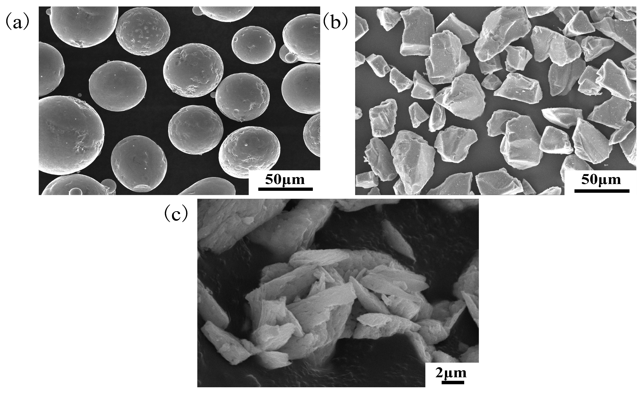
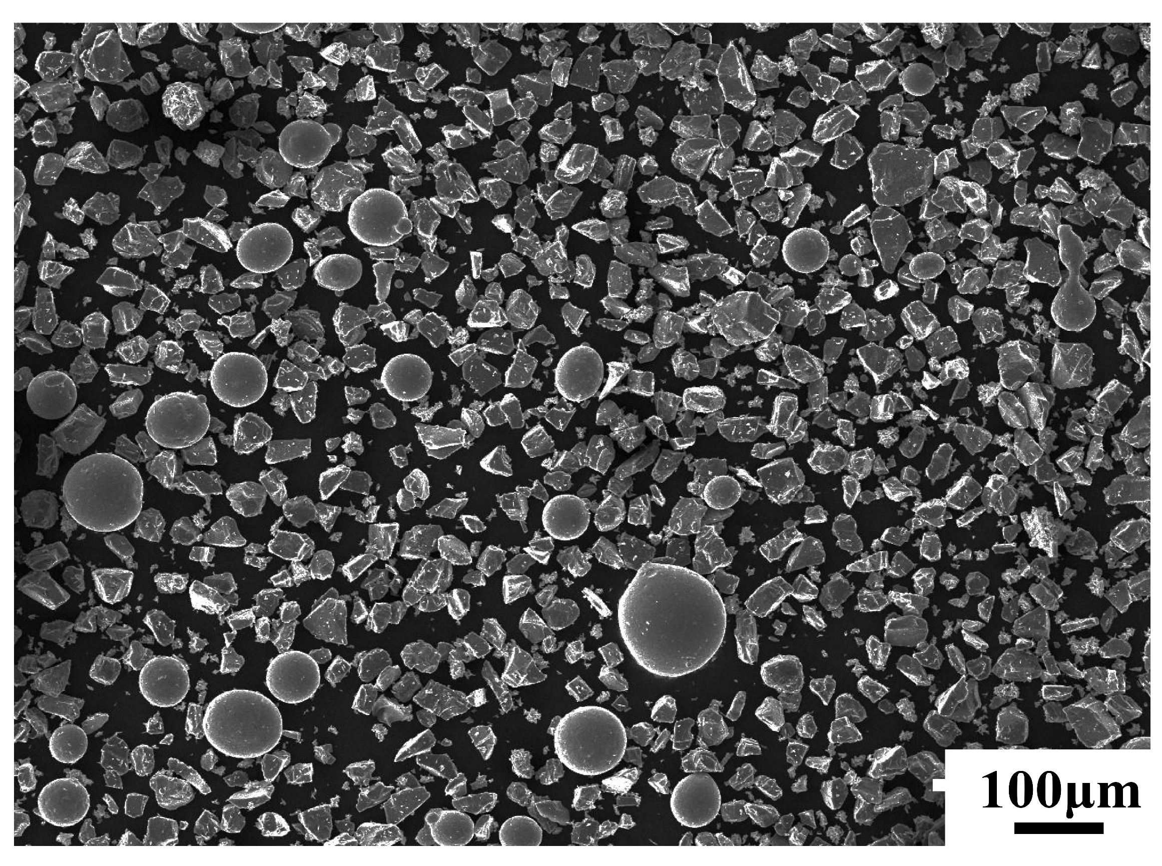
2.1. Experimental Materials
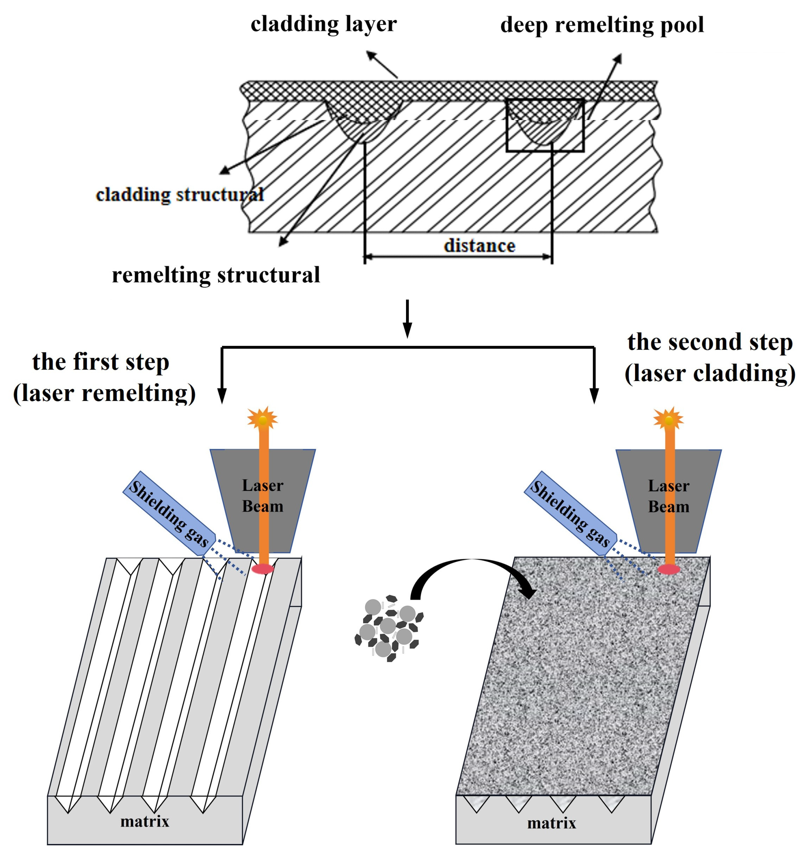
2.2. Sample Preparation
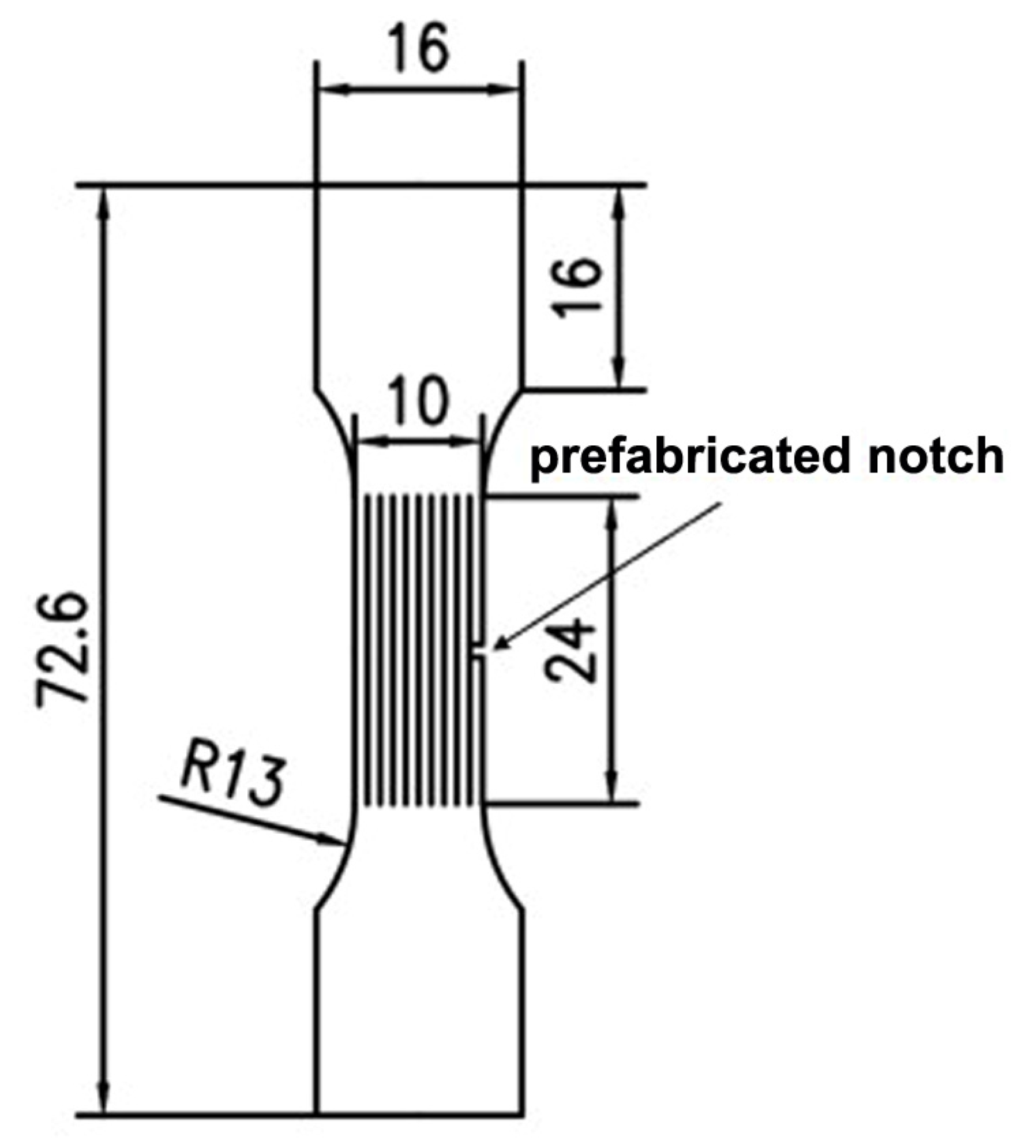
2.3. Performance Characterization
3. Results and Discussion
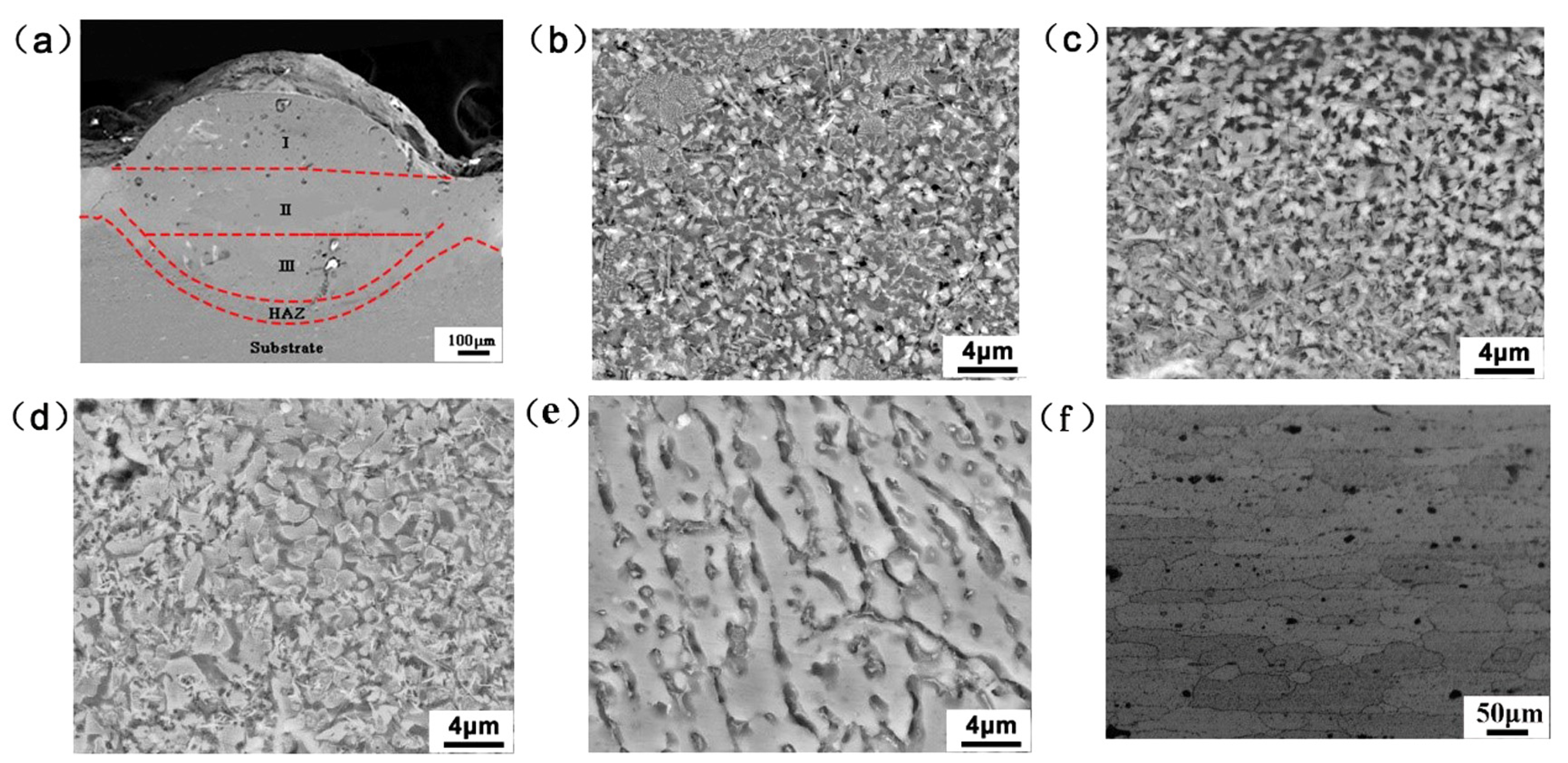
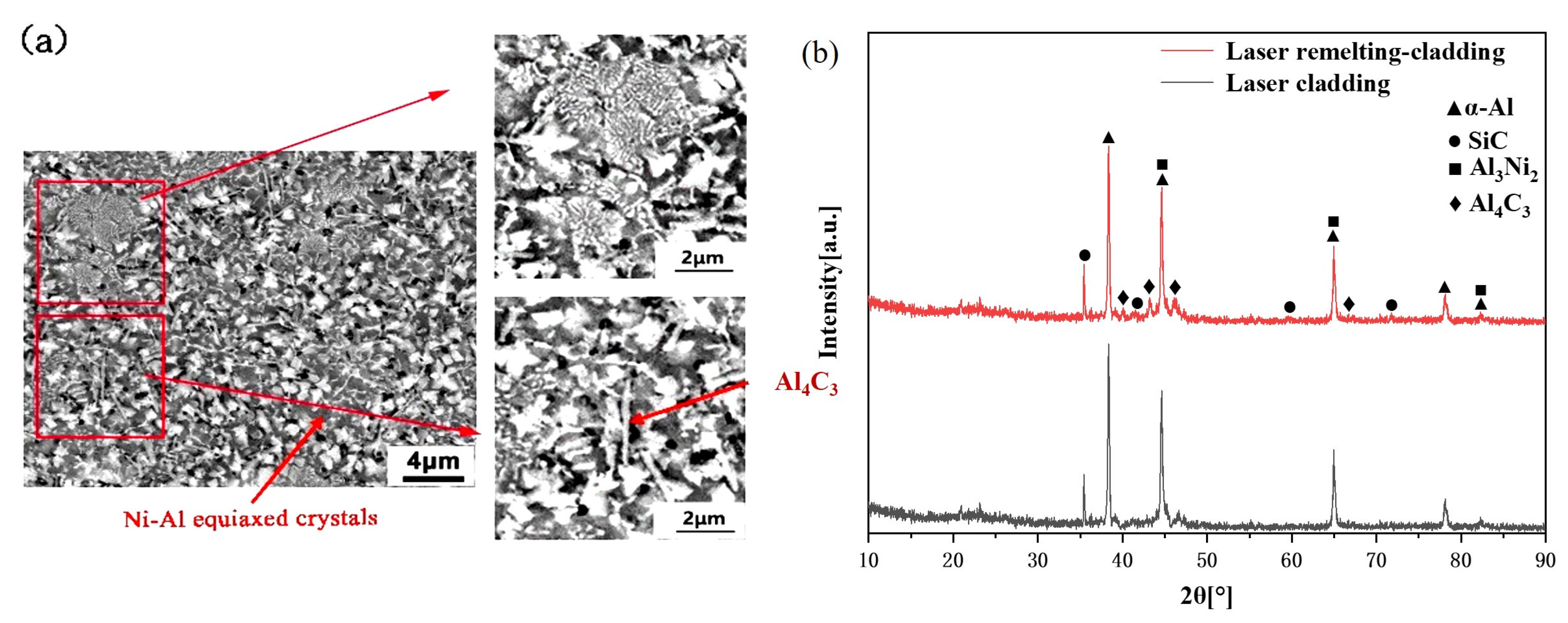
3.1. Microstructure
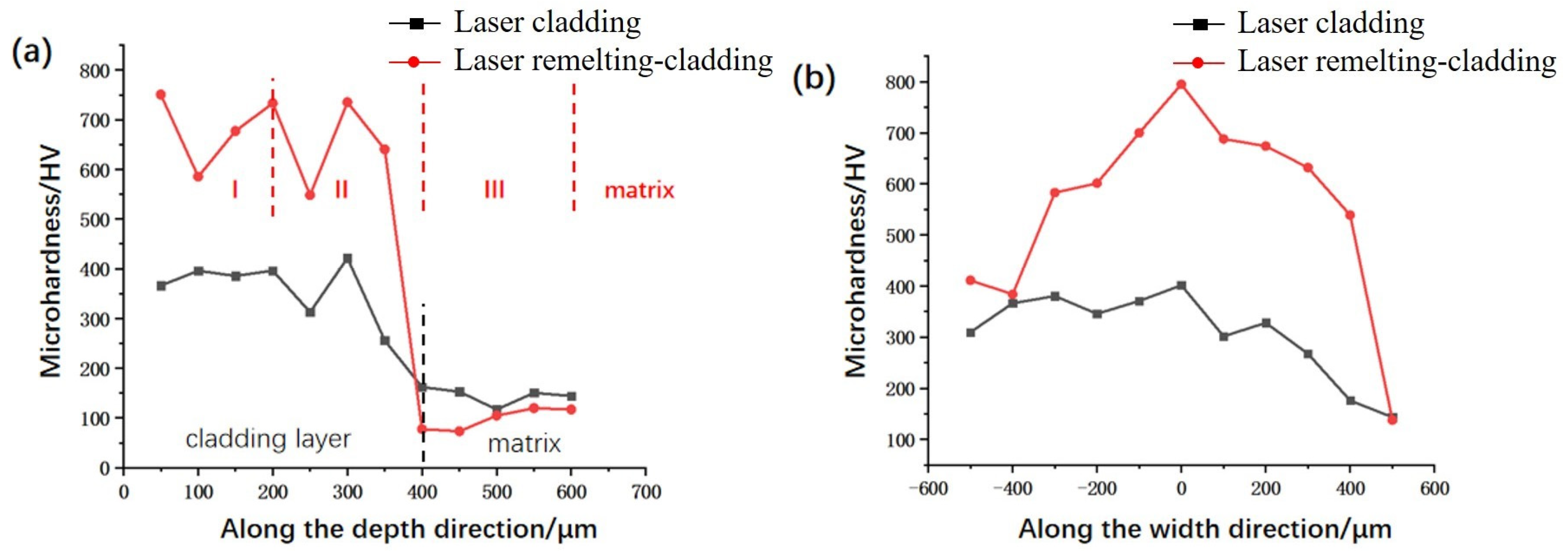
3.2. Microhardness
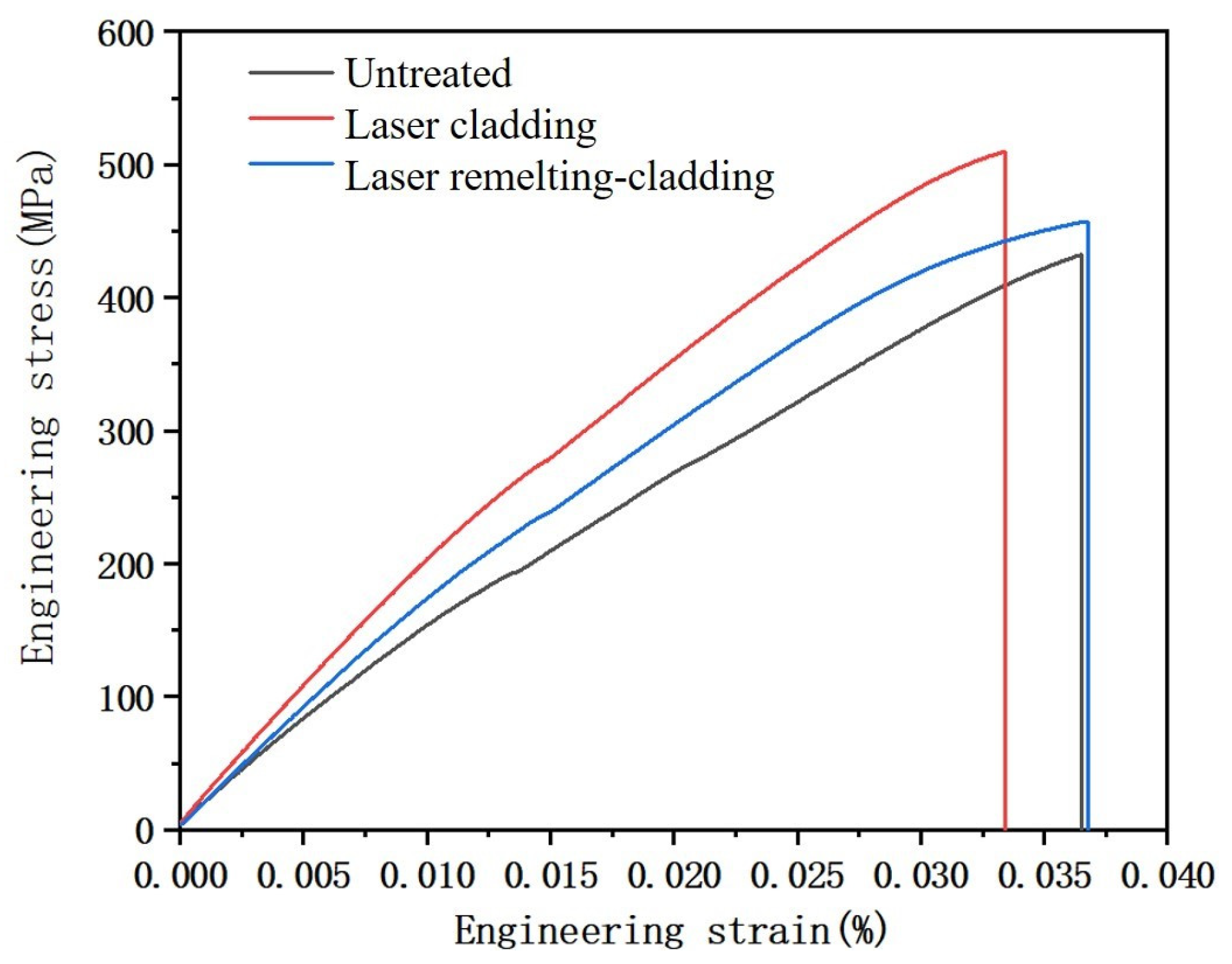
3.3. Tensile Results
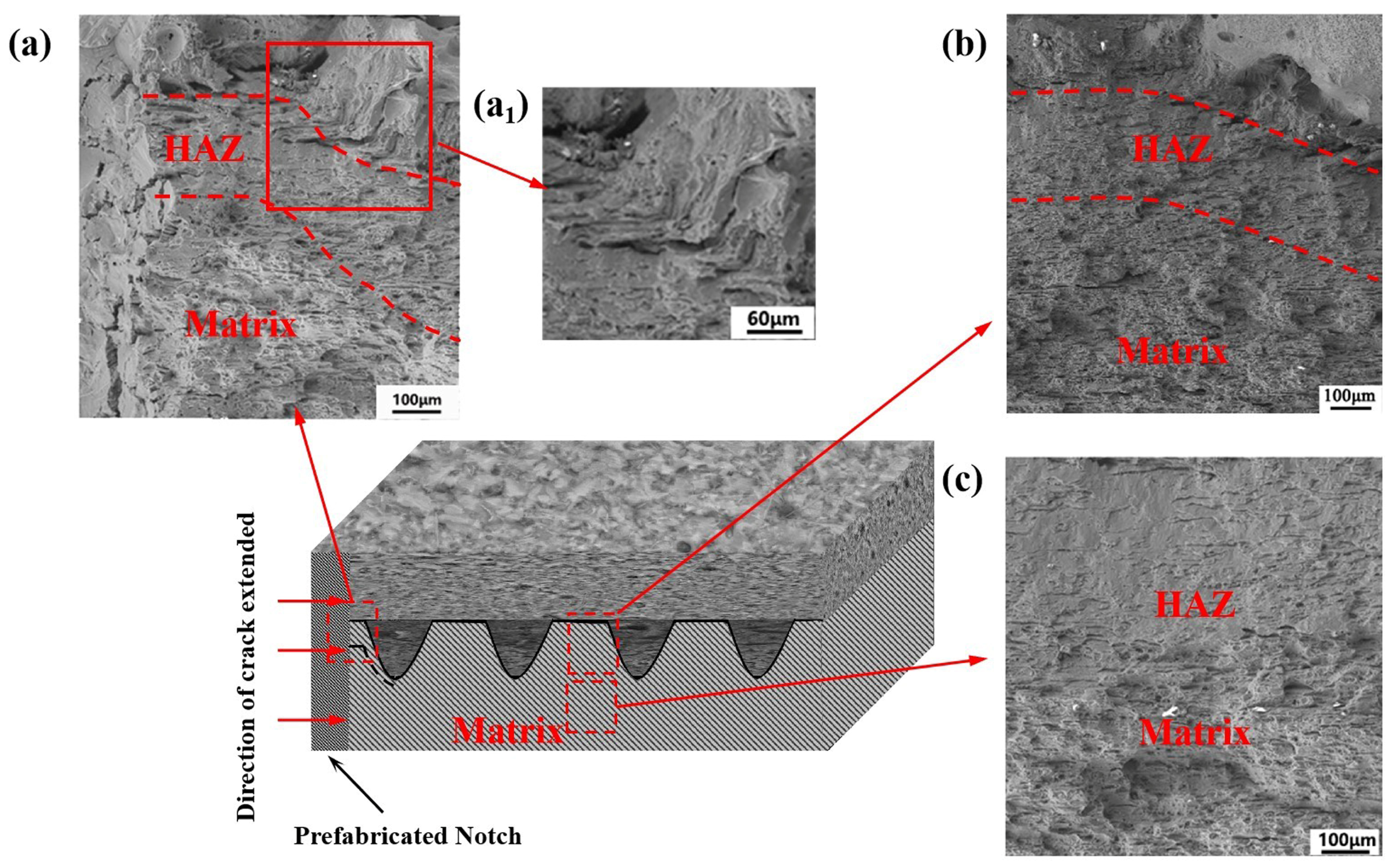
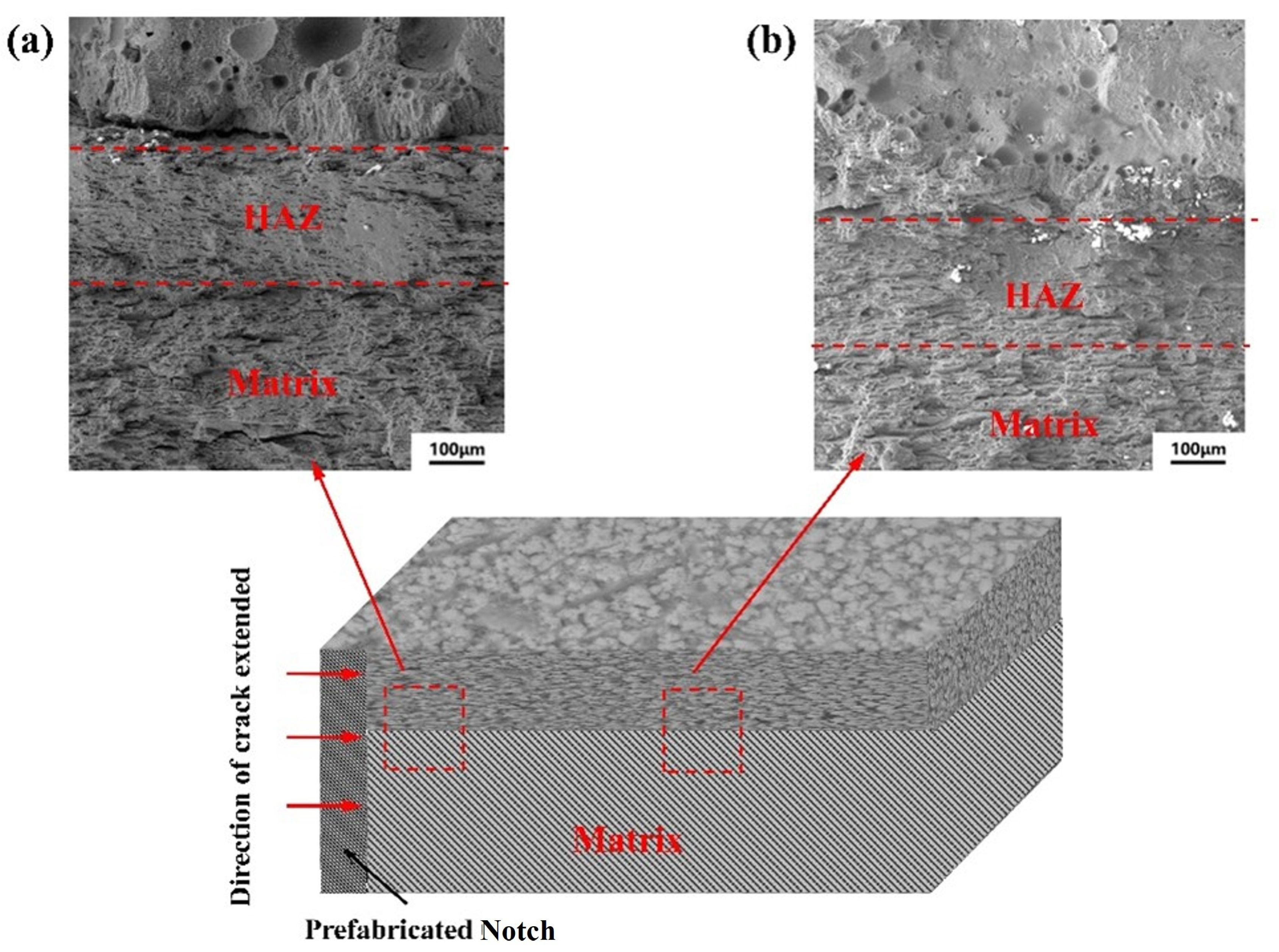
3.4. Analysis of Fracture Morphology
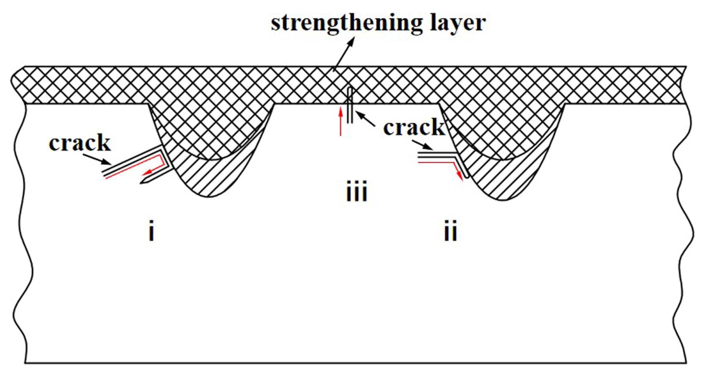
3.5. Fracture Mechanism Analysis
4. Conclusions
- 1.
- Compared with the untreated samples, the microstructure of the treated samples was more compact. In addition, the microhardness of treated samples was significantly increased markedly improved.
- 2.
- Compared with the samples with cladding layer, the strength of samples with the remelting-cladding layer was reduced, but its toughness was significantly improved, which not only meet the requirements of toughness but also could increase the strength of materials. After stretching, the fracture surface of the two samples showed a small number of dimples and tearing edges, which showed quasi-cleavage fracture.
- 3.
- The stretching mechanism was studied. The grains of the remelting-cladding layer with deep remelting pools were more refined and the structure was denser, which hindered the initiation of cracks and prolonged the crack path.
Author Contributions
Funding
Data Availability Statement
Conflicts of Interest
References
- Cheng, X. Study of Thermal Stability and Properties of 7075 Aluminum Alloy during Friction Stir Processing. Master’s Thesis, Chongqing University, Chongqing, China, 2019. [Google Scholar]
- Wang, Y. Effect of Deformation Heat Treatment on Microstructure and Properties of Friction Stir Processing of 7075 Aluminum Alloy. Master’s Thesis, Chongqing University, Chongqing, China, 2020. [Google Scholar]
- Lin, R.; Liu, B.; Zhang, J.; Zhang, S. Microstructure evolution and properties of 7075 aluminum alloy recycled from scrap aircraft aluminum alloys. J. Mater. Res. Technol. 2022, 19, 354–367. [Google Scholar] [CrossRef]
- Liu, M.; Shan, Z.; Li, X.; Zang, Y. Hot tensile deformation behavior and microstructure evolution of 7075 aluminum alloy sheet. J. Mater. Res. Technol. 2023, 24, 724–736. [Google Scholar] [CrossRef]
- Imran, M.; Khan, A.A. Characterization of Al-7075 metal matrix composites: A review. J. Mater. Res. Technol. 2019, 8, 3347–3356. [Google Scholar] [CrossRef]
- Zhang, Y.; Yang, L.; Fan, Z.; Pang, S.; Chen, W. Evaluation of tensile creep behavior of spray formed and extruded 7075 aluminum alloy by equivalent stress. J. Mater. Res. Technol. 2023, 22, 1476–1490. [Google Scholar] [CrossRef]
- Zheng, K.L.; Wei, X.S.; Yan, B.; Yan, P.F. Ceramic waste SiC particle-reinforced Al matrix composite brake materials with a high friction coefficient. Wear 2020, 458, 203424. [Google Scholar] [CrossRef]
- Jiang, L.; Jiang, Y.; Yu, L.; Yang, H.; Li, Z.; Ding, Y. Thermo-mechanical coupling analyses for al alloy brake discs with Al2O3-SiC (3D)/Al alloy composite wear-resisting surface layer for high-speed trains. Materials 2019, 12, 3155. [Google Scholar] [CrossRef] [PubMed]
- Puchi-Cabrera, E.; Staia, M.; Santana, Y.; Mora-Zorrilla, E.; Lesage, J.; Chicot, D.; La Barbera-Sosa, J.; Ochoa-Perez, E.; Villalobos-Gutierrez, C. Fatigue behavior of AA7075-T6 aluminum alloy coated with a WC–10Co–4Cr cermet by HVOF thermal spray. Surf. Coat. Technol. 2013, 220, 122–130. [Google Scholar] [CrossRef]
- Subramani, S.; Devarajan, M. Structural and surface analysis of chemical vapor deposited boron doped aluminum nitride thin film on aluminum substrates. Mater. Sci.-Pol. 2019, 37, 395–403. [Google Scholar] [CrossRef]
- Wu, J.; Liu, R.; Wang, B.; Yang, C.; Qu, Y.; Xue, W. Preparation and characterization of carburized layer on pure aluminum by plasma electrolysis. Surf. Coat. Technol. 2015, 269, 119–124. [Google Scholar] [CrossRef]
- Jung, A.; Buchwalder, A.; Hegelmann, E.; Hengst, P.; Zenker, R. Surface engineering of spray-formed aluminium-silicon alloys by plasma nitriding and subsequent electron beam remelting. Surf. Coat. Technol. 2018, 335, 166–172. [Google Scholar] [CrossRef]
- Dai, W.B.; Yuan, L.X.; Li, C.Y.; He, D.; Zhang, Y.M. The effect of surface roughness of the substrate on fatigue life of coated aluminum alloy by micro-arc oxidation. J. Alloys Compd. 2018, 765, 1018–1025. [Google Scholar] [CrossRef]
- Li, X.; Huang, S.; Tang, J.; Mu, W.; Xu, X.; Chen, X. Effects of laser machining aluminum alloy in different media. Micromachines 2022, 13, 1130. [Google Scholar] [CrossRef] [PubMed]
- Liu, W.; Huang, S.; Du, S.; Gao, T.; Zhang, Z.; Chen, X.; Huang, L. The Effects of heat treatment on microstructure and mechanical properties of selective laser melting 6061 aluminum alloy. Micromachines 2022, 13, 1059. [Google Scholar] [CrossRef] [PubMed]
- Sui, Q.; Cheng, D.; Dong, Y.; Ma, Y.; Su, Y.; Hu, N.; Sun, Z.; Chen, Y. Effect of Reticulate Unit Spacing on Microstructure and Properties of Biomimetic 7075 Aluminum Alloy by Laser Cladding. Micromachines 2023, 14, 418. [Google Scholar] [CrossRef] [PubMed]
- Siddiqui, A.A.; Dubey, A.K. Recent trends in laser cladding and surface alloying. Opt. Laser Technol. 2021, 134, 106619. [Google Scholar] [CrossRef]
- Song, M.; Wu, L.; Liu, J.; Hu, Y. Effects of laser cladding on crack resistance improvement for aluminum alloy used in aircraft skin. Opt. Laser Technol. 2021, 133, 106531. [Google Scholar] [CrossRef]
- Wang, J.; Timokhina, I.; Sharp, K.; Shekhter, A.; Liu, Q. Microstructure and precipitation behaviours of laser clad 7075 aluminium alloy. Surf. Coat. Technol. 2022, 445, 128726. [Google Scholar] [CrossRef]
- Li, Y.; Zhang, P.; Bai, P.; Wu, L.; Liu, B.; Zhao, Z. Microstructure and properties of Ti/TiBCN coating on 7075 aluminum alloy by laser cladding. Surf. Coat. Technol. 2018, 334, 142–149. [Google Scholar] [CrossRef]
- Wang, C.; Gao, Y.; Wang, R.; Wei, D.; Cai, M.; Fu, Y. Microstructure of laser-clad Ni60 cladding layers added with different amounts of rare-earth oxides on 6063 Al alloys. J. Alloys Compd. 2018, 740, 1099–1107. [Google Scholar] [CrossRef]
- Liu, Y.; Sun, R.; Niu, W.; Zhang, T.; Lei, Y. Effects of CeO2 on microstructure and properties of TiC/Ti2Ni reinforced Ti-based laser cladding composite coatings. Opt. Lasers Eng. 2019, 120, 84–94. [Google Scholar] [CrossRef]
- Liang, C.J.; Wang, C.L.; Zhang, K.X.; Liang, M.L.; Xie, Y.G.; Liu, W.J.; Yang, J.J.; Zhou, S.F. Nucleation and strengthening mechanism of laser cladding aluminum alloy by Ni-Cr-B-Si alloy powder based on rare earth control. J. Mater. Process. Technol. 2021, 294, 117145. [Google Scholar] [CrossRef]
- Nazemi, N.; Urbanic, J.; Alam, M. Hardness and residual stress modeling of powder injection laser cladding of P420 coating on AISI 1018 substrate. Int. J. Adv. Manuf. Technol. 2017, 93, 3485–3503. [Google Scholar] [CrossRef]
- Liu, Q.; Janardhana, M.; Hinton, B.; Brandt, M.; Sharp, K. Laser cladding as a potential repair technology for damaged aircraft components. Int. J. Struct. Integr. 2011, 2, 314–331. [Google Scholar] [CrossRef]
- Katipelli, L.R.; Agarwal, A.; Dahotre, N.B. Laser surface engineered TiC coating on 6061 Al alloy: Microstructure and wear. Appl. Surf. Sci. 2000, 153, 65–78. [Google Scholar] [CrossRef]
- Zhou, H.; Tong, X.; Zhang, Z.; Li, X.; Ren, L. The thermal fatigue resistance of cast iron with biomimetic non-smooth surface processed by laser with different parameters. Mater. Sci. Eng. A 2006, 428, 141–147. [Google Scholar] [CrossRef]
- Yuan, Y.; Zhao, G.; Zhang, P.; Zhou, H. Effects of shapes of biomimetic coupling units on wear resistance of 7075 aluminum alloy. Opt. Laser Technol. 2020, 121, 105786. [Google Scholar] [CrossRef]
- Zhang, Z.; Zhou, H.; Ren, L.; Tong, X.; Shan, H.; Li, X. Surface morphology of laser tracks used for forming the non-smooth biomimetic unit of 3Cr2W8V steel under different processing parameters. Appl. Surf. Sci. 2008, 254, 2548–2555. [Google Scholar] [CrossRef]
- Kamat, S.; Su, X.; Ballarini, R.; Heuer, A.H. Structural basis for the fracture toughness of the shell of the conch Strombus gigas. Nature 2000, 405, 1036–1040. [Google Scholar] [CrossRef]
- Zhao, G.; Yuan, Y.; Wang, H.; Li, X.; Zhang, P.; Zhou, T.; Lin, H.; Jin, X.; Deng, Y. Study on wear properties of 7075 aluminum alloy by laser alloying imitating shell surface structure with different unit spacing. Mater. Chem. Phys. 2023, 297, 127327. [Google Scholar] [CrossRef]
- Yuan, Y.; Zhang, P.; Zhao, G.; Gao, Y.; Tao, L.; Chen, H.; Zhang, J.; Zhou, H. Effects of laser energies on wear and tensile properties of biomimetic 7075 aluminum alloy. J. Mater. Eng. Perform. 2018, 27, 1361–1368. [Google Scholar] [CrossRef]
- Chen, Z.K.; Zhou, T.; Zhang, H.F.; Yang, W.S.; Zhou, H. Influence of orientations of bionic unit fabricated by laser remelting on fatigue wear resistance of gray cast iron. J. Mater. Eng. Perform. 2015, 24, 2511–2520. [Google Scholar] [CrossRef]
- Cui, C.; Guo, Z.; Liu, Y.; Xie, Q.; Wang, Z.; Hu, J.; Yao, Y. Characteristics of cobalt-based alloy coating on tool steel prepared by powder feeding laser cladding. Opt. Laser Technol. 2007, 39, 1544–1550. [Google Scholar] [CrossRef]
- Grum, J.; Šturm, R. Deformation of specimen during laser surface remelting. J. Mater. Eng. Perform. 2000, 9, 138–146. [Google Scholar] [CrossRef]


| Si | Fe | Cu | Mn | Mg | Cr | Zn | Ti | Al | Others |
|---|---|---|---|---|---|---|---|---|---|
| 0.06 | 0.16 | 1.51 | 0.04 | 2.63 | 0.22 | 5.53 | 0.03 | Bal | <0.15 |
| Current A | Pulse Duration ms | Frequency Hz | Scanning Speed mm/min | Defocus Value Mm | |
|---|---|---|---|---|---|
| Laser cladding | 120 | 5 | 5 | 30 | 5 |
| Laser remelting | 95 | 5 | 10 | 30 | 0 |
| Sample | EI, % | UTS, MPa |
|---|---|---|
| Untreated | 0.0365 | 430.20 |
| Laser Cladding | 0.0334 | 509.35 |
| Laser Remelting-Cladding | 0.0367 | 456.73 |
Disclaimer/Publisher’s Note: The statements, opinions and data contained in all publications are solely those of the individual author(s) and contributor(s) and not of MDPI and/or the editor(s). MDPI and/or the editor(s) disclaim responsibility for any injury to people or property resulting from any ideas, methods, instructions or products referred to in the content. |
© 2023 by the authors. Licensee MDPI, Basel, Switzerland. This article is an open access article distributed under the terms and conditions of the Creative Commons Attribution (CC BY) license (https://creativecommons.org/licenses/by/4.0/).
Share and Cite
Sui, Q.; Hu, N.; Su, Y.; Wang, Y.; Song, X. Tensile Property of 7075 Aluminum Alloy with Strengthening Layer by Laser Remelting-Cladding Treatment. Micromachines 2023, 14, 2017. https://doi.org/10.3390/mi14112017
Sui Q, Hu N, Su Y, Wang Y, Song X. Tensile Property of 7075 Aluminum Alloy with Strengthening Layer by Laser Remelting-Cladding Treatment. Micromachines. 2023; 14(11):2017. https://doi.org/10.3390/mi14112017
Chicago/Turabian StyleSui, Qi, Ning Hu, Yingrui Su, Yan Wang, and Xiaolei Song. 2023. "Tensile Property of 7075 Aluminum Alloy with Strengthening Layer by Laser Remelting-Cladding Treatment" Micromachines 14, no. 11: 2017. https://doi.org/10.3390/mi14112017