
A Review of Research Progress on Machining Carbon Fiber-Reinforced Composites with Lasers

 ,
, 
Abstract
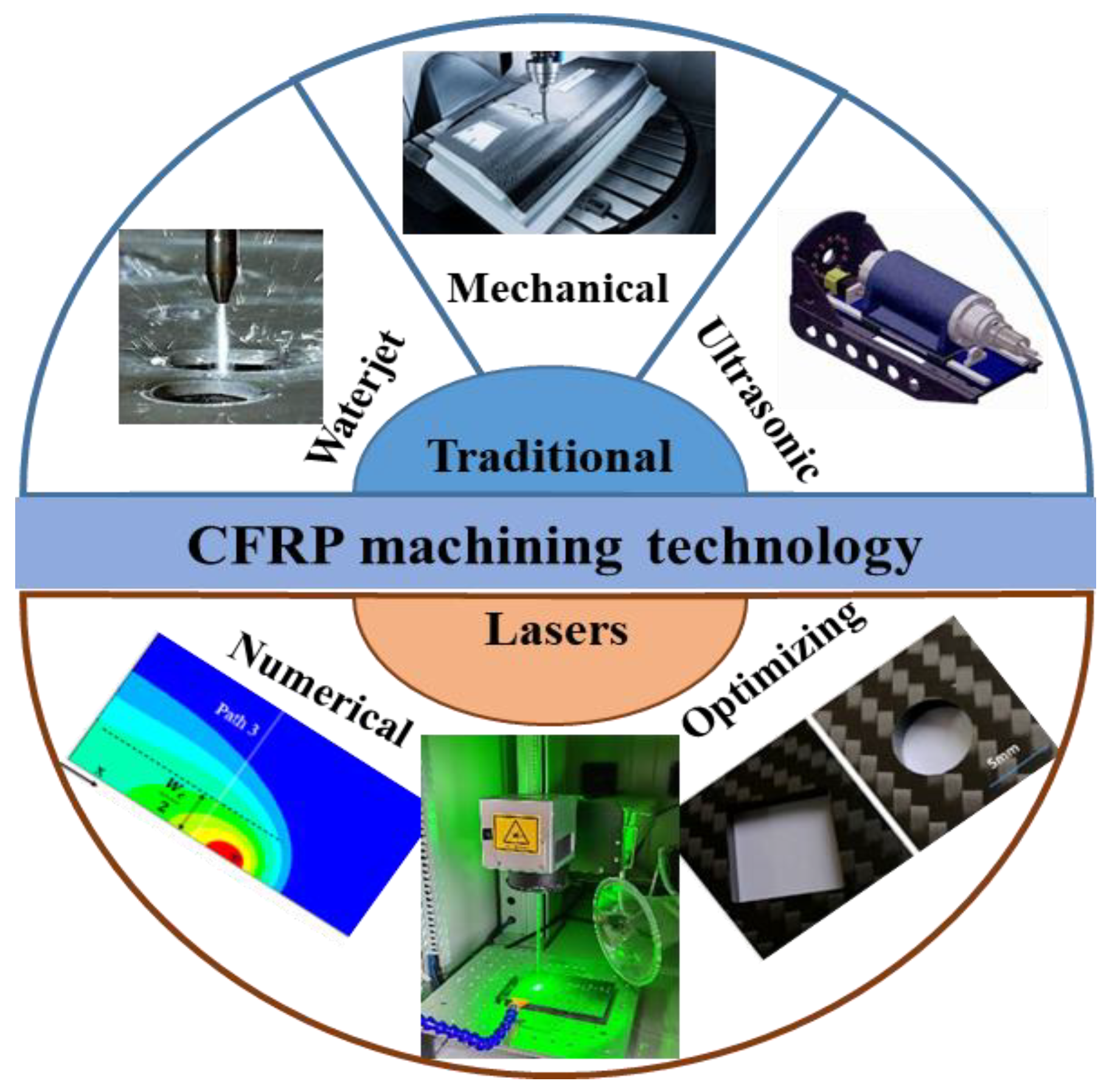
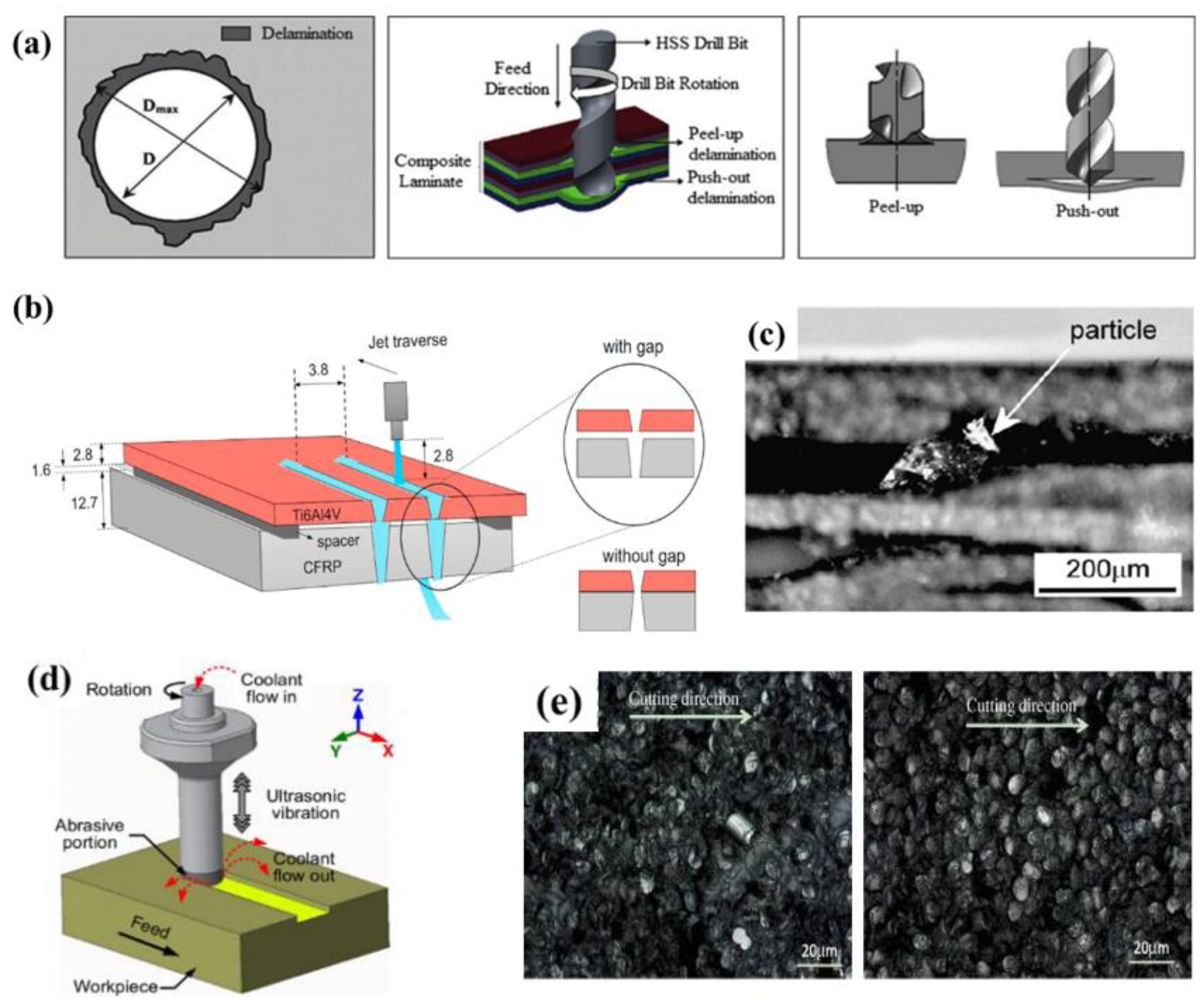
:1. Introduction

2. CFRP Laser Processing Optimization
2.1. Effect of Laser Wavelength on CFRP Machining Quality
2.2. Effect of Laser Mode and Parameters on CFRP Machining Quality
2.3. CFRP Field-Assisted Laser Processing Method


3. CFRP Laser Processing Theoretical Model and Numerical Simulation
4. Conclusions
- (1)
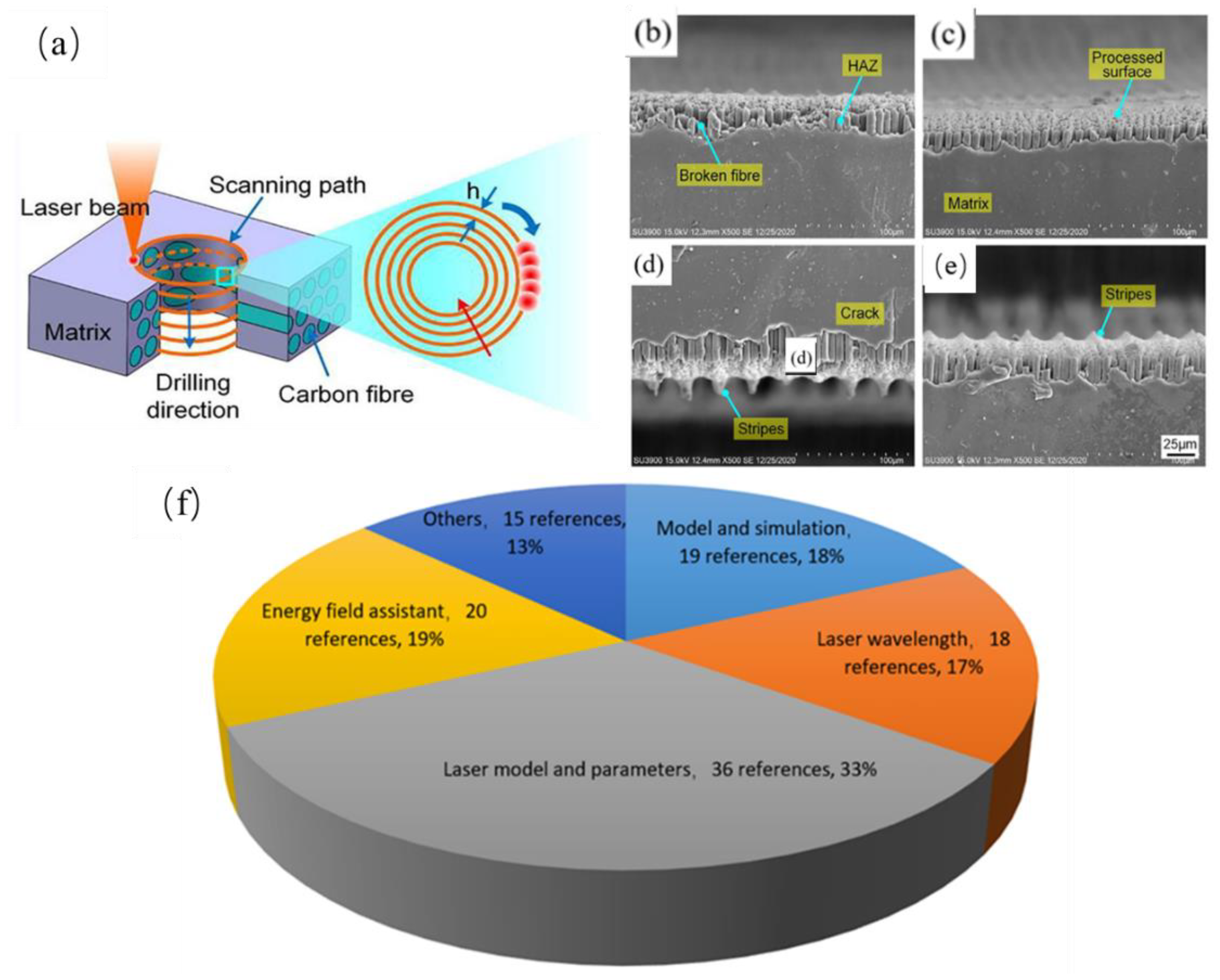
- Comparing the CFRP cutting quality with CW laser and pulsed laser, it can be found that it has a higher processing efficiency but a larger thermal effect for CW laser. So, CW laser is suitable for CFRP cutting which require low processing accuracy and high cutting efficiency. Different scanning strategies (process optimization) can be used in the future to process carbon fiber composites with high efficiency and high quality. For pulsed lasers, the HAZ can be effectively reduced on the CFRP surface due to the continuous periodic cooling time between the adjacent pulses. So, it is suitable for the machining CFRP component which requires high-precision and low-damage. Moreover, the selection of suitable laser parameters (pulse width, frequency, scanning path, etc.) is conducive to the cooling of materials in the processing process and improves the processing quality.
- (2)
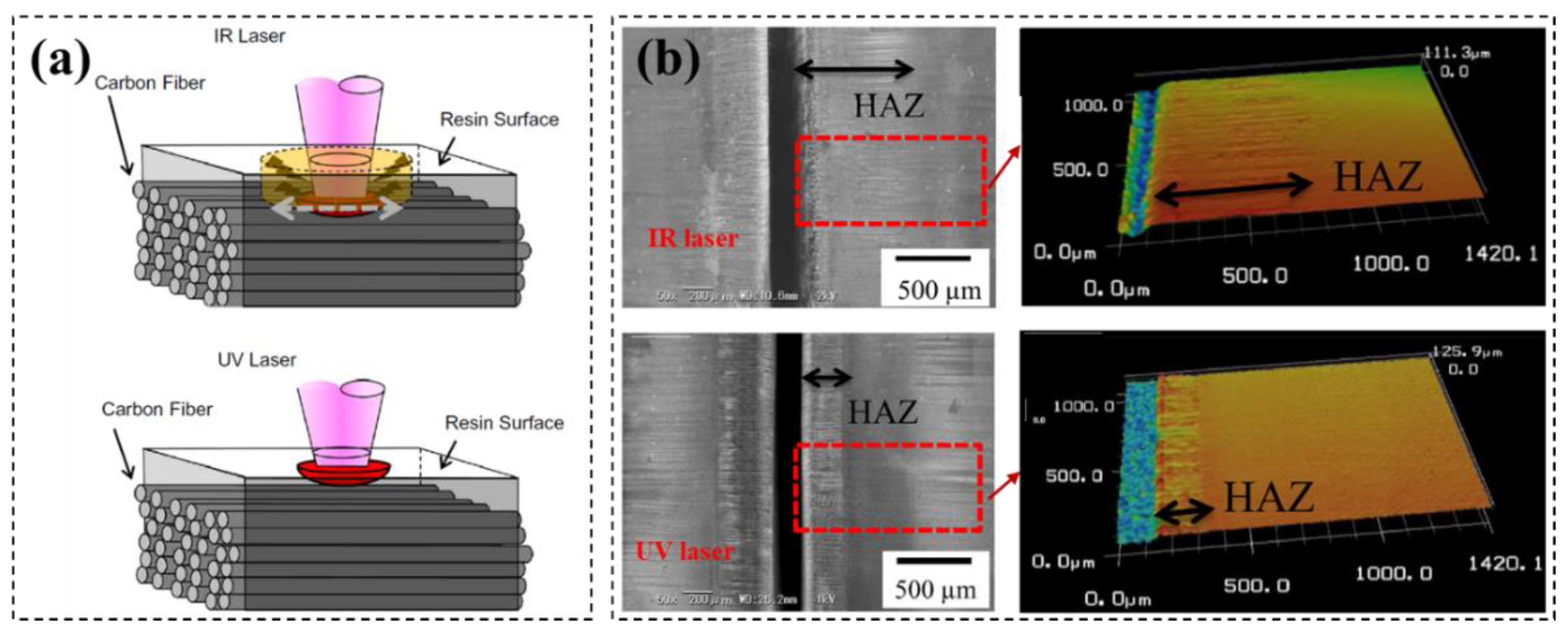
- CFRP has different absorption coefficient for lasers with different wavelength. For the infrared laser, the polymer matrix absorption rate of laser is less than 15%, and 85% of the energy pass through the polymer matrix to heat the carbon fibers directly. On the other hand, the UV laser energy is absorbed by the resin matrix almost completely. To this end, the CFRP material removal mechanism is different for these two types of lasers, and the UV laser has a better cutting edge quality than the IR laser, and the HAZ is larger for IR laser than that for UV laser. In this regard, in the future, we can use high-power ultraviolet lasers for high-precision, low-damage CFRP cutting.
- (3)
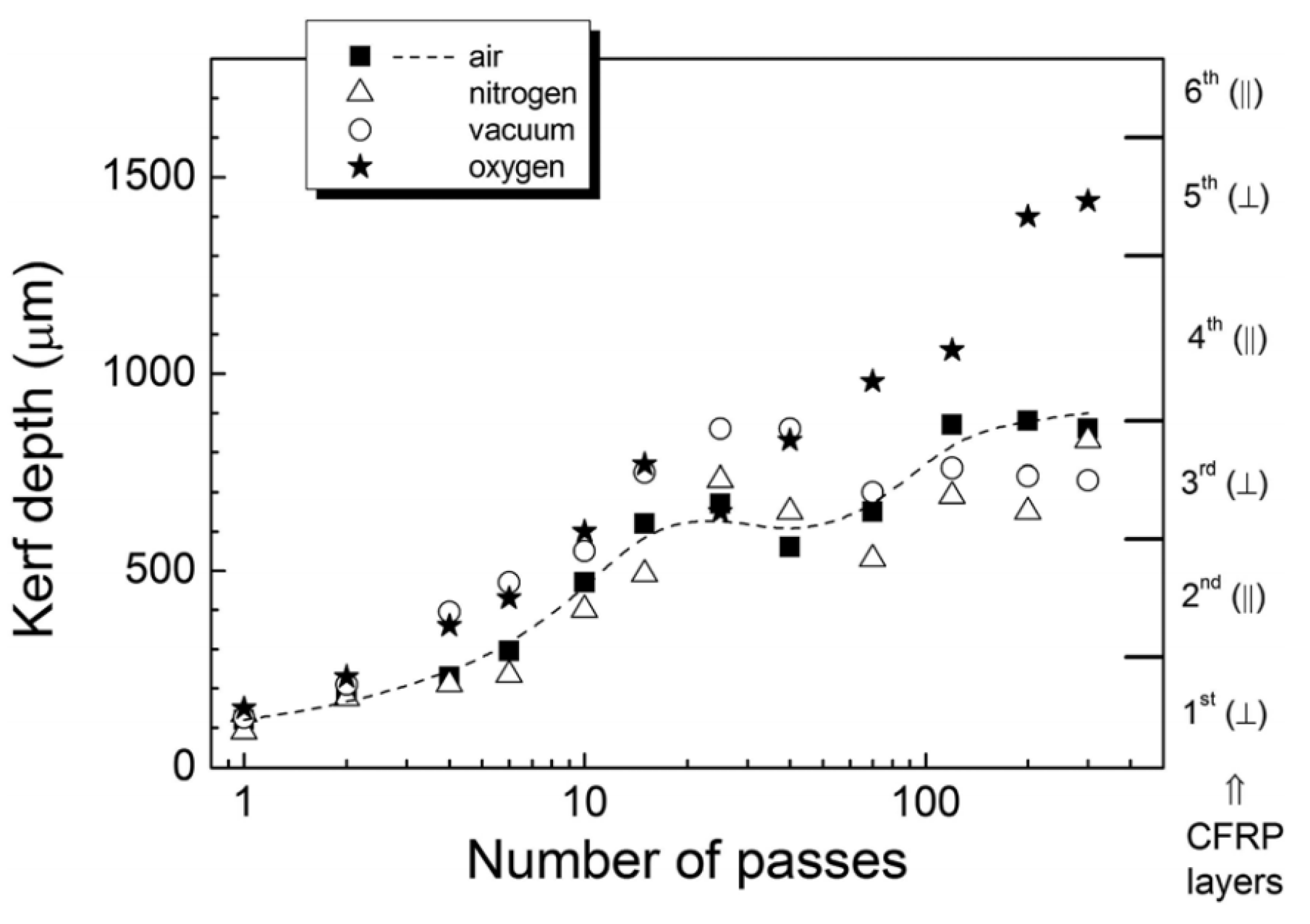
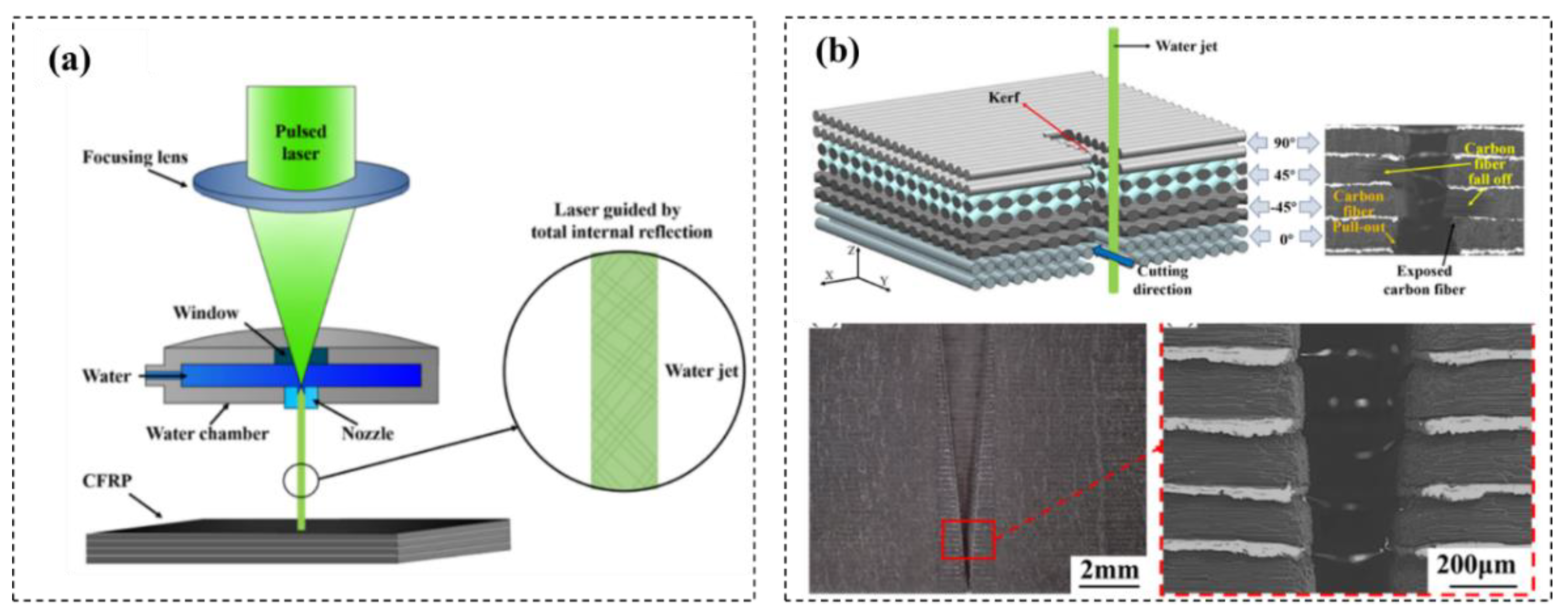
- Cutting CFRP with energy field assistant laser machining method can improve the cutting efficiency and quality. Summarizing the common auxiliary means in the laser processing process, such as water-assisted laser processing, gases-assisted laser processing and underwater processing. All of these techniques can control the extraction of fibers and reduce the accumulation of residual heat in the processing area, so as to achieve a high cutting quality. In the future, other energy filed can be introduced in CFRP laser cutting to improve the quality and efficiency such as magnetic field, electric field, ultrasonic field, flow field and external force field, which needs further investigated.
- (4)
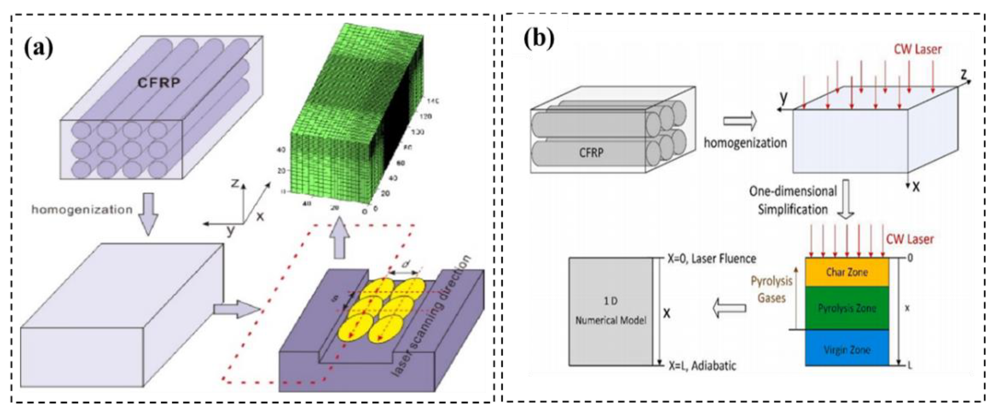
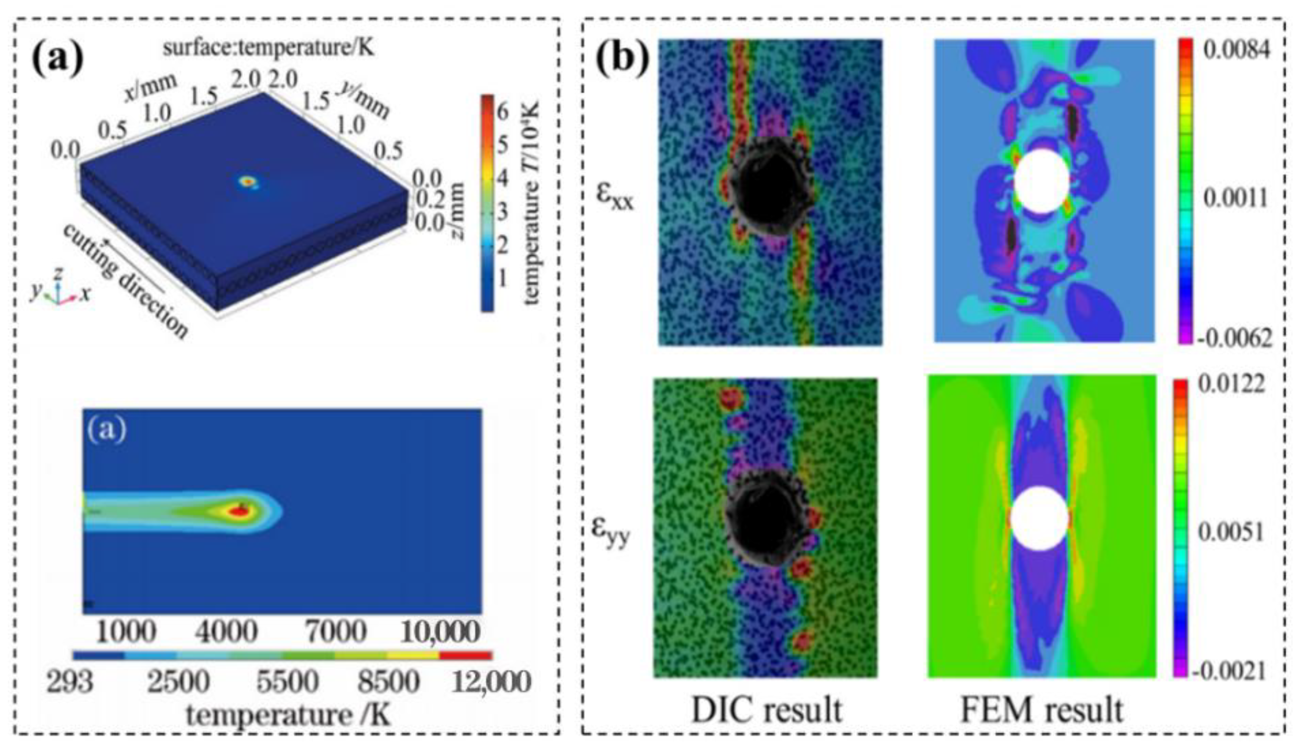
- To understand the mechanism of CFRP laser cutting and with lasers more clearly and obtained the temperature distribution in cutting process, the numerical multi-physics model was established, and the simulation analysis was carried out by using finite element method. The cut seam width and the thermal impact zone with different laser parameters can be predicted, which providing a certain theoretical and experimental basis for laser cutting of CFRP. However, the numerical analysis of material removal physical process of CFRP under the action of short pulse laser is still lacking, especially the simulation of temperature field, stress field and material removal process under the action of ultrashort pulse laser, such as femtosecond laser and picosecond laser, which needs further research.
Author Contributions
Funding
Data Availability Statement
Conflicts of Interest
References
- Barile, C.; Casavola, C.; Cililis, F.D. Mechanical comparison of new composite materials for aerospace applications. Compos. Part B 2019, 162, 122–128. [Google Scholar] [CrossRef]
- Li, H.L.; Fiore, L.; Jiang, Z. Composite materials for primary aircraft structures: From development phase to high volume production rate. Civ. Aircr. Des. Res. 2020, 1, 125–128. [Google Scholar]
- Liu, S.L.; Chen, T.; Wu, C.Q. Rotary ultrasonic face grinding of carbon fiber reinforced plastic (CFRP): A study on cutting force model. Int. J. Adv. Manuf. Technol. 2017, 89, 847–856. [Google Scholar] [CrossRef]
- Ning, F.D.; Cong, W.L.; Hu, Y.B.; Wang, H. Additive manufacturing of carbon fiber-reinforced plastic composites using fused deposition modeling: Effects of process parameters on tensile properties. J. Compos. Mater. 2017, 51, 451–462. [Google Scholar] [CrossRef]
- Shi, H.Y.; Yuan, S.M.; Zhang, C.; Chen, B.C.; Li, Q.L.; Li, Z.; Zhu, G.Y.; Qian, J.Q. A cutting force prediction model for rotary ultrasonic side grinding of CFRP composites considering coexistence of brittleness and ductility. Int. J. Adv. Manuf. Technol. 2020, 106, 2403–2414. [Google Scholar] [CrossRef]
- Zhang, D.Z.; Wang, H.; Anthony, R.; Cong, W.L. Delamination in rotary ultrasonic machining of CFRP composites: Finite element analysis and experimental implementation. Int. J. Adv. Manuf. Technol. 2020, 107, 3847–3858. [Google Scholar] [CrossRef]
- Criado, V.; Feito, N.; Guisandez, J.L.C.; Diaz-Lvarez, J. A New Cutting Device Design to Study the Orthogonal Cutting of CFRP Laminates at Different Cutting Speeds. Materials 2019, 12, 4074. [Google Scholar] [CrossRef] [Green Version]
- Li, H.; Qin, X.D.; Huang, T.; Liu, X.P.; Sun, D.; Jin, Y. Machining quality and cutting force signal analysis in UD-CFRP milling under different fiber orientation. Int. J. Adv. Manuf. Technol. 2018, 98, 2377–2387. [Google Scholar] [CrossRef]
- Koklu, U.; Morkavuk, S. Cryogenic drilling of carbon fiber-reinforced composite. Surf. Rev. Lett. 2019, 101, 1509–1523. [Google Scholar] [CrossRef]
- Sezer, M.; Uğur, K.; Mehmet, B.; Lokman, G. Cryogenic machining of carbon fiber reinforced plastic (CFRP) composites and the effects of cryogenic treatment on tensile properties: A comparative study. Compos. Part B 2018, 147, 1–11. [Google Scholar]
- Wang, H.X.; Zhang, X.H.; Duan, Y.G. Effects of drilling area temperature on drilling of carbon fiber reinforced polymer composites due to temperature-dependent properties. Int. J. Adv. Manuf. Technol. 2018, 96, 2943–2951. [Google Scholar] [CrossRef]
- Mohsin, A.; Li, X.; Dong, Y.; Liu, G.J. Assessment of Cutting Performance of Cemented Tungsten Carbide Drills in Drilling Multidirectional T700 CFRP Plate. J. Manuf. Mater. Process. 2018, 2, 43. [Google Scholar]
- Chen, Y.; Ge, E.D.; Fu, Y.C.; Su, H.H.; Xu, J.H. Review and prospect of drilling technologies for carbon fiber reinforced polymer. Acta Mater. Compos. Sin. 2015, 32, 301–306. [Google Scholar]
- Zhang, L.F.; Wang, S.; Qiao, W.L.; Li, Z.; Wang, N.; Zhang, J.; Wang, T. High-speed milling of CFRP composites: A progressive damage model of cutting force. Int. J. Adv. Manuf. Technol. 2020, 106, 1005–1015. [Google Scholar] [CrossRef]
- Fu, R.; Zhen, Y.J.; Wang, F.J.; Jin, Y.; Sun, D.; Yang, L.J.; Cheng, D. Drill-exit temperature characteristics in drilling of UD and MD CFRP composites based on infrared thermography. Int. J. Mach. Tools Manuf. 2018, 135, 24–37. [Google Scholar] [CrossRef]
- Meltem, A.K.; Hasan, G.K. A review on machinability of carbon fiber reinforced polymer (CFRP) and glass fiber reinforced polymer (GFRP) composite materials. Def. Technol. 2018, 14, 318–326. [Google Scholar]
- Prasad, D.; Gayakwad, M.D.; Patil, N.G.; Pawade, R.S.; Thakur, D.G.; Brahmankar, P.K. Experimental Investigations into Abrasive Waterjet Machining of Carbon Fiber Reinforced Plastic. J. Compos. 2015, 2015, 9. [Google Scholar]
- Li, M.J.; Lin, X.C.; Yang, X.J.; Wu, H.; Meng, X.M. Study on kerf characteristics and surface integrity based on physical energy model during abrasive waterjet cutting of thick CFRP laminates. Int. J. Adv. Manuf. Technol. 2021, 113, 73–85. [Google Scholar] [CrossRef]
- Fermin, B.; Alejandro, S.; Moises, B.; Bartolome, S.; Jorge, S. Study of the surface quality of carbon fiber–reinforced thermoplastic matrix composite (CFRTP) machined by abrasive water jet (AWJM). Int. J. Adv. Manuf. Technol. 2020, 107, 3299–3313. [Google Scholar]
- Alejandro, S.; Fermin, B.; Jorge, S.; Bartolome, S.; Moises, B. Kerf Taper Defect Minimization Based on Abrasive Waterjet Machining of Low Thickness Thermoplastic Carbon Fiber Composites C/TPU. Materials 2019, 12, 4192. [Google Scholar]
- Rishi, P.; Ramulu, M.; Mohamed, H. Surface quality and kerf width prediction in abrasive water jet machining of metal-composite stacks. Compos. Part B 2019, 175, 107134. [Google Scholar]
- Dhiraj, K.; Suhasini, G. Abrasive waterjet machining of Ti/CFRP/Ti laminate and multi-objective optimization of the process parameters using response surface methodology. J. Compos. Mater. 2019, 54, 1741–1759. [Google Scholar]
- Alberdi, A.; Artaza, T.; Suárez, A.; Rivero, A.; Girot, F. An experimental study on abrasive waterjet cutting of CFRP/Ti6Al4V stacks for drilling operations. Int. J. Adv. Manuf. Technol. 2016, 86, 691–704. [Google Scholar] [CrossRef] [Green Version]
- Alexandru, P.I.; Nicolae, B.; Ioana, P.A. Avoiding carbon fibre reinforced polymer delamination during abrasive water jet piercing: A new piercing method. Int. J. Adv. Manuf. Technol. 2021, 119, 1139–1152. [Google Scholar]
- Masoud, F.; Sapuan, S.M.; Ariffin, M.K.A.M.; Nukman, Y.; Bayraktar, E. Experimental analysis of kerf taper angle in cutting process of sugar palm fiber reinforced unsaturated polyester composites with laser beam and abrasive water jet cutting technologies. Polymers 2021, 13, 2543. [Google Scholar] [CrossRef]
- Selzer, R.; Friedrich, K. Mechanical properties and failure behavior of carbon fibre reinforced polymer composites under the influence of moisture. Compos. Part A 1997, 28, 595–604. [Google Scholar] [CrossRef]
- El-Hofy, M.; Helmy, M.O.; Escobar-Palafox, G.; Kerrigan, K.; Scaife, R.; El-Hofy, H. Abrasive Water Jet Machining of Multidirectional CFRP Laminates. Procedia CIRP 2018, 68, 535–540. [Google Scholar] [CrossRef]
- Shanmugam, D.K.; Nguyen, T.; Wang, J. A study of delamination on graphite/epoxy composites in abrasive waterjet machining. Compos. Part A 2008, 39, 923–929. [Google Scholar] [CrossRef]
- Azmir, M.A.; Ahsan, A.K. A study of abrasive water jet machining process on glass/epoxy composite laminate. J. Mater. Process. Technol. 2009, 209, 6168–6173. [Google Scholar] [CrossRef]
- Li, Z.C.; Jiao, Y.; Deines, T.W.; Pei, Z.J.; Treadwell, C. Rotory ultrasonic machining of ceramic matrix composites: Feasibility study and designed experiments. Int. J. Mach. Tools Manuf. 2005, 45, 1402–1411. [Google Scholar] [CrossRef]
- Ning, F.D.; Cong, W.L.; Wang, H.; Hu, Y.B.; Hu, Z.L.; Pei, Z.J. Surface grinding of CFRP composites with rotary ultrasonic machining: A mechanistic model on cutting force in the feed direction. Int. J. Adv. Manuf. Technol. 2017, 92, 1217–1229. [Google Scholar] [CrossRef]
- Cong, W.L.; Pei, Z.J.; Feng, Q.; Deines, T.W.C. Rotary ultrasonic machining of CFRP: A comparison with twist drilling. J. Reinf. Plast. Compos. 2012, 31, 313–321. [Google Scholar] [CrossRef]
- Xu, W.X.; Zhang, L.C.; Wu, Y.B. Elliptic vibration—Assisted cutting of fibre reinforced polymer composites: Understanding the material removal mechanisms. Compos. Sci. Technol. 2014, 92, 103–111. [Google Scholar] [CrossRef]
- Sulaiman, F.A.; Yilabas, B.S.; Ahsan, M.M. Laser hole drilling of composites and steel workpieces. Lasers Eng. 2014, 16, 105–120. [Google Scholar]
- Leone, C.; Genna, S.; Tagliaferri, V. Fibre laser cutting of CFRP thin sheets by multi-passes scan technique. Opt. Lasers Eng. 2014, 53, 43–50. [Google Scholar] [CrossRef]
- El-Hofy, M.H.; El-Hofy, H. Laser beam machining of carbon fiber reinforced composites: A review. Int. J. Adv. Manuf. Technol. 2019, 101, 2965–2975. [Google Scholar] [CrossRef]
- Fischer, F.; Romolli, L.; Kling, R. Laser based repair of carbon fiber reinforced plastics. CIRP Ann. 2010, 59, 203–206. [Google Scholar] [CrossRef]
- Herzog, D.; Jaeschke, P.; Meier, O.; Haferkamp, H. Investigations on the thermal effect caused by laser cutting with respect to static strength of CFRP. Int. J. Mach. Tools Manuf. 2008, 48, 1464–1473. [Google Scholar] [CrossRef]
- Mishra, Y.K.; Mishra, S.; Jayswal, S.C. Parametric Analysis and Optimization of Inclined Laser Percussion Drilling of Carbon Fiber Reinforced Plastic Using Solid-State Nd: YAG Laser. Lasers Manuf. Mater. Process. 2021, 8, 325–354. [Google Scholar] [CrossRef]
- Canel, T.; Kayahan, E.; Sinmazcelik, T. Laser process parameter optimization of dimple created on oriented carbon fiber reinforced epoxy composites. J. Compos. Mater. 2021, 55, 4029–4043. [Google Scholar] [CrossRef]
- Webber, R.; Hafaner, M.; Michalowski, A.; Graf, T. Minimum damage in CFRP laser processing. Phys. Procedia 2011, 12, 302–307. [Google Scholar] [CrossRef] [Green Version]
- Pagano, N.; Ascari, A.; Loverrani, E.; Donati, L.; Campana, G.; Fortunato, A. Laser interaction with carbon fibre reinforced polymers. Procedia CIRP 2015, 33, 423–427. [Google Scholar] [CrossRef]
- Wu, C.W.; Wu, X.Q.; Huang, C.G. Ablation behaviors of carbon reinforced polymer composites by laser of different operation modes. Opt. Laser Technol. 2015, 73, 23–28. [Google Scholar] [CrossRef] [Green Version]
- Zhou, L.; Huang, P.; Jiao, H.; Zhang, G.; Zhao, Z.; Lin, Z. Study on mechanism of spray-mist-assisted laser processing of carbon fiber reinforced plastic. Opt. Laser Technol. 2023, 158, 108821. [Google Scholar] [CrossRef]
- Joost, S.; Saeid, H.; Gaǽtan, P.; Van Wim, P.; Mathias, K. Enhanced low power vibrothermography of impacted CFRP through in-plane local defect resonances. Proc. Meet. Acoust. 2019, 38, 065003. [Google Scholar]
- Takaha, S.K.; Tsukamoto, M.; Masuno, S.; Sato, Y. Heat conduction analysis of laser CFRP processing with IR and UV laser light. Compos. Part A 2016, 84, 114–122. [Google Scholar] [CrossRef]
- Xu, H.B.; Hu, J.; Yu, Z. Absorption behavior analysis of carbon fiber reinforced polymer in laser processing. Opt. Mater. Express 2015, 5, 2330–2336. [Google Scholar] [CrossRef]
- Wolynski, A.; Herrmann, T.; Mucha, P. Laser ablation of CFRP using picosecond laser pulses at different wavelengths from UV to IR. Phys. Procedia 2011, 12, 292–301. [Google Scholar] [CrossRef] [Green Version]
- Qi, L.T.; Liu, F.C.; Zhang, Y.D. Experimental investigation on 266nm ultraviolet solid-state laser cutting of carbon fiber reinforced plastics. Laser Technol. 2022, 46, 402–407. [Google Scholar]
- Li, Y.; Zhan, X.H.; Gao, C.Y.; Wang, H.G.; Yang, Y. Comparative study of infrared laser surface treatment and ultraviolet laser surface treatment of CFRP laminates. Int. J. Adv. Manuf. Technol. 2019, 102, 4059–4071. [Google Scholar] [CrossRef]
- Zhan, X.H.; Li, Y.; Gao, C.Y.; Wang, H.G.; Yang, Y. Effect of infrared laser surface treatment on the microstructure and properties of adhesively CFRP bonded joints. Opt. Laser Technol. 2018, 106, 398–409. [Google Scholar] [CrossRef]
- Li, W.Y.; Zhang, G.J.; Huang, Y.; Rong, Y.M. UV laser high-quality drilling of CFRP plate with a new interlaced scanning mode. Compos. Struct. 2021, 273, 114258. [Google Scholar] [CrossRef]
- Gao, Q.Y.; Li, Y.; Wang, H.G.; Liu, W.P.; Shen, H.L.; Zhan, X.H. Effect of Scanning Speed with UV Laser Cleaning on Adhesive Bonding Tensile Properties of CFRP. Appl. Compos. Mater. 2019, 26, 1087–1099. [Google Scholar] [CrossRef]
- Wang, S.Q.; Jesse, E.; Luis, T.; Kiana, P.; Xiang, L.Z.; Liu, Y.T. Ultrahigh Resolution Pulsed Laser-Induced Photoacoustic Detection of Multi-Scale Damage in CFRP Composites. Appl. Sci. 2020, 10, 2106. [Google Scholar] [CrossRef]
- Loutas, T.H.; Sotiriadis, G.; Tsonos, E.; Psarras, S.; Kostopoulos, V. Investigation of a pulsed laser ablation process for bonded repair purposes of CFRP composites via peel testing and a design-of-experiments approach. Int. J. Adhes. Adhes. 2019, 95, 102407. [Google Scholar] [CrossRef]
- Toyama, N.; Yamamoto, T.; Tsuda, H. Ultrasonic inspection of adhesively bonded CFRP/aluminum joints using pulsed laser scanning. Adv. Compos. Mater. 2019, 28, 27–35. [Google Scholar] [CrossRef]
- Goeke, A.; Emmelmann, C. Influence of laser cutting parameters on CFRP part quality. Phys. Procedia 2010, 5, 253–258. [Google Scholar] [CrossRef] [Green Version]
- Klotzbach, A.; Hauser, M.; Beyer, E. Laser cutting of carbon fiber reinforced polymers using highly brilliant laser beam sources. Phys. Procedia 2011, 12, 572–577. [Google Scholar] [CrossRef]
- Bluemel, S.; Jaeschke, P.; Wippo, V.; Bastick, S.; Haferkamp, H. Laser machining of CFRP using a high power fiber laser—Investigations on the heat affected zone. In Proceedings of the 15th European Conference on Composite Materials, Venice, Italy, 24–28 June 2012. [Google Scholar]
- Rao, S.; Sethi, A.; Das, A.K.; Mandal, N.; Kiran, P. Fiber laser cutting of CFRP composites and process optimization through response surface methodology. Mater. Manuf. Process. 2017, 32, 1612–1621. [Google Scholar] [CrossRef]
- Bluemel, S.; Jaeschke, P.; Suttmann, O.; Overmeyer, L. Comparative study of achievable quality cutting carbon fibre reinforced thermoplastics using continuous wave and pulsed laser sources. Phys. Procedia 2014, 56, 1143–1152. [Google Scholar] [CrossRef] [Green Version]
- Riveiro, A.; Quintero, F.; Lusquiños, F.; Delval, J.; Comesana, R.; Boutinguiza, M.; Pou, J. Experimental study on the CO2 laser cutting of carbon fiber reinforced plastic composite. Compos. Part A Appl. Sci. Manuf. 2012, 43, 1400–1409. [Google Scholar] [CrossRef]
- Kumar, D.; Gururaja, S. Investigation of hole quality in drilled Ti/CFRP/Ti laminates using CO 2 laser. Opt. Laser Technol. 2020, 126, 106130. [Google Scholar] [CrossRef]
- Li, M.J.; Li, S.; Yang, X.J.; Zhang, Z.C. Fiber laser cutting of CFRP laminates with single and multi-pass strategy: A feasibility study. Opt. Laser Technol. 2018, 107, 443–453. [Google Scholar] [CrossRef]
- Sehyeok, O.; Inyong, L.; Park, Y.B.; Hyungson, K. Investigation of cut quality in fiber laser cutting of CFRP. Opt. Laser Technol. 2019, 113, 129–140. [Google Scholar]
- Wang, J.W.; Zhu, Y.X.; Wei, C.H.; Lv, Y.W.; Ma, Z.L.; Wang, L.J.; Feng, G.B. Tensile strength prediction of orthogonal CFRP under high intensity CW laser irradiation. AIP Adv. 2019, 9, 105304. [Google Scholar] [CrossRef]
- Li, M.J.; Li, S.; Yang, X.J.; Zhang, Y.; Liang, Z.C. Effect of lay-up configuration and processing parameters on surface quality during fiber laser cutting of CFRP laminates. Int. J. Adv. Manuf. Technol. 2019, 100, 623–635. [Google Scholar] [CrossRef]
- Tao, N.R.; Chen, G.Y.; Yu, T.Y.; Li, W.; Fan, L.C. Dual-beam laser drilling process for thick carbon fiber reinforced plastic composites plates. J. Mater. Process. Tech. 2019, 281, 116590. [Google Scholar] [CrossRef]
- Leone, C.; Genna, S. Heat affected zone extension in pulsed Nd:YAG laser cutting of CFRP. Compos. Part B 2018, 140, 174–182. [Google Scholar] [CrossRef]
- Kononenko, V.I.; Konov, T. Graf. Residual heat generated during laser processing of CFRP with picosecond laser pulses. Adv. Opt. Technol. 2018, 7, 157–163. [Google Scholar]
- Rodolfo, L.; Frank, P.; John, C.; William, Y.; James, F.G. Surface characterization of carbon fiber reinforced polymers by picosecond laser induced breakdown spectroscopy. Spectrochim. Acta Part B At. Spectrosc. 2018, 140, 5–12. [Google Scholar]
- Sato, Y.; Tsukamoto, M.; Abe, N. Thermal effect on CFRP ablation with a 100-W class pulse fiber laser using a PCF amplifier. Appl. Surf. Sci. 2017, 417, 250–255. [Google Scholar] [CrossRef]
- Jiang, H.; Ma, C.W.; Li, M.; Cao, Z.L. Femtosecond Laser Drilling of Cylindrical Holes for Carbon Fiber-Reinforced Polymer (CFRP) Composites. Molecules 2021, 26, 2953. [Google Scholar] [CrossRef] [PubMed]
- Freitag, C.; Onuseit, V.; Weber, R.; Graf, T. High-speed observation of the heat flow in CFRP during laser processing. Phys. Procedia 2012, 39, 171–178. [Google Scholar] [CrossRef] [Green Version]
- Li, X.; Hou, W. Investigation on the Continuous Wave Mode and the ms Pulse Mode Fiber Laser Drilling Mechanisms of the Carbon Fiber Reinforced Composite. Polymers 2020, 12, 706. [Google Scholar] [CrossRef] [Green Version]
- Yang, R.; Huang, Y.; Rong, Y.; Wu, C.; Liu, W.; Chen, L. Evaluation and classification of CFRP kerf width by acoustic emission in nanosecond laser cutting. Opt. Laser Technol. 2022, 152, 108165. [Google Scholar] [CrossRef]
- Salama, A.; Li, L.; Mativenga, P. High-power picosecond laser drilling/machining of carbon fibre reinforced polymer (CFRP) composites. Appl. Phys. A 2016, 122, 73. [Google Scholar] [CrossRef]
- Li, W.Y.; Zhang, G.J.; Huang, Y.; Rong, Y.M. Drilling of CFRP plates with adjustable pulse duration fiber laser. Mater. Manuf. Process. 2021, 36, 1256–1263. [Google Scholar] [CrossRef]
- Ma, Y.; Xin, C.; Zhang, W.; Jin, G.Y. Experimental Study of Plasma Plume Analysis of Long Pulse Laser Irradiates CFRP and GFRP Composite Materials. Crystals 2021, 11, 545. [Google Scholar] [CrossRef]
- Dhiraj, K.; Gerhard, L.; Suhasini, G. Formation of sub-wavelength laser induced periodic surface structure and wettability transformation of CFRP laminates using ultra-fast laser. Mater. Lett. 2020, 276, 128282. [Google Scholar]
- Freitag, C.; Kononenko, T.V.; Weber, R.; Konov, V.I.; Graf, T. Influence of pulse repetition rate and pulse energy on the heat accumulation between subsequent laser pulses during laser processing of CFRP with ps pulses. Appl. Phys. A 2018, 124, 479. [Google Scholar] [CrossRef]
- Hu, J.; Zhu, D.Z. Investigation of Carbon Fiber Reinforced Plastics Machining Using 355 nm Picosecond Pulsed Laser. Appl. Compos. Mater. 2018, 25, 589–600. [Google Scholar] [CrossRef]
- Oliveira, V.; Sharma, S.P.; Vilar, R. Vilar. Surface treatment of CFRP composites using femtosecond laser radiation. Opt. Lasers Eng. 2017, 94, 37–43. [Google Scholar] [CrossRef]
- Dittmar, H.; Gäbler, F.; Stute, U. UV-laser Ablation of Fibre Reinforced Composites with Ns-Pulses. Phys. Procedia 2013, 41, 266–275. [Google Scholar] [CrossRef] [Green Version]
- Wang, Y.F.; Hu, J.; Li, K.M. Defect control strategy of carbon fiber reinforced polymer during nanosecond ultraviolet laser processing. Mater. Res. Express 2019, 6, 085608. [Google Scholar] [CrossRef]
- Jiang, Y.; Chen, G.Y.; Zhou, C.; Zhang, Y. Research of carbon fiber reinforced plastic cut by picosecond laser. Laser Technol. 2017, 41, 821–825. [Google Scholar]
- Weber, R.; Freitag, C.; Kononenko, T.V.; Hafner, M.; Onuseit, V.; Berger, P.; Graf, T. Short-pulse laser processing of CFRP. Phys. Procedia 2012, 39, 137–146. [Google Scholar] [CrossRef] [Green Version]
- Peter, J.; Klaus, S.; Stefan, B.; Overmeyer, L. Cutting and drilling of carbon fiber reinforced plastics (CFRP) by 70W short pulse nanosecond laser. Proc. SPIE-Int. Soc. Opt. Eng. 2014, 89630, 89630S. [Google Scholar]
- Xu, J.; Jing, C.; Jiao, J.; Sun, S.; Sheng, L.; Zhang, Y.; Xia, H.; Zeng, K. Experimental Study on Carbon Fiber reinforced composites cutting with nanosecond laser. Materials 2022, 15, 6686. [Google Scholar] [CrossRef]
- Ouyang, W.T.; Jiao, J.K.; Xu, Z.F.; Sheng, L.Y. Experimental study on CFRP drilling with the picosecond laser “double rotation” cutting technique. Opt. Laser Technol. 2021, 142, 107238. [Google Scholar] [CrossRef]
- Riveiro, A.; Quintero, F.; Lusquinos, F.; Comesa, R.; Boutinguiza, M.; Pou, J. Laser cutting of carbon fiber composite materials. Procedia Manuf. 2017, 13, 388–395. [Google Scholar] [CrossRef]
- Negarestani, R.; Li, L.; Sezer, H.K. Nanosecond pulsed DPSS Nd:YAG laser cutting of CFRP composites with mixed reactive and inert gases. Int. J. Adv. Manuf. Technol. 2010, 49, 553–566. [Google Scholar] [CrossRef]
- Ramanujam, N.; Dhanabalan, S.; Raj, K.D.; Jeyaprakash, N. Investigation of micro-hole quality in drilled CFRP laminates through Co2 laser. Arab. J. Sci. Eng. 2021, 46, 7557–7575. [Google Scholar] [CrossRef]
- Kononenko, T.V.; Freitag, C.; Komlenok, M.S.; Onuseit, V.; Weber, R.; Graf, T.; Konov, V.I. Oxygen-assisted multipass cutting of carbon fiber reinforced plastics with ultra-short laser pulses. J. Appl. Phys. 2014, 115, 103107. [Google Scholar] [CrossRef]
- Zhang, C.; Yuan, G.F.; Cong, Q.D.; Gguo, B.C. Study of the water jet assisted laser cutting carbon fiber reinforced plastic (CFRP) composites. Laser J. 2018, 39, 68–71. [Google Scholar]
- Wu, Y.W.; Zhang, G.Y.; Wang, J.X.; Chao, Y.; Zhang, W.W. The cutting process and damage mechanism of large thickness CFRP based on water jet guided laser processing. Opt. Laser Technol. 2021, 141, 107140. [Google Scholar] [CrossRef]
- Viboon, T.; Ketsada, K.; Huan, Q. Investigation into laser machining of carbon fiber reinforced plastic in a flowing water layer. Int. J. Adv. Manuf. Technol. 2019, 104, 3629–3645. [Google Scholar]
- Hua, Y.Q.; Xiao, T.; Xue, Q.; Liu, H.X.; Chen, R.F. Experimental study about laser cutting of carbon fiber reinforced polymer. Laser Technol. 2013, 37, 565–570. [Google Scholar]
- Sun, D.; Han, F.Z.; Ying, W.S. The experimental investigation of water jet–guided laser cutting of CFRP. Int. J. Adv. Manuf. Technol. 2019, 102, 719–729. [Google Scholar] [CrossRef]
- Li, H.N.; Ye, Y.X.; Du, T.T.; Zhao, Y. The effect of thermal damage on mechanical strengths of CFRP cut with different pulse-width lasers. Opt. Laser Technol. 2022, 153, 108219. [Google Scholar] [CrossRef]
- Xu, H.B.; Hu, J. Modeling of the material removal and heat affected zone formation in CFRP short pulsed laser processing. Appl. Math. Model. 2017, 46, 354–364. [Google Scholar] [CrossRef]
- Li, X.; Hou, W.; Han, B.; Xu, L.F.; Li, Z.W.; Nan, P.Y.; Ni, X.W. Thermal response during volumetric ablation of carbon fiber composites under a high intensity continuous laser irradiation. Surf. Interfaces 2021, 23, 101032. [Google Scholar] [CrossRef]
- Ge, J.; Cheng, X.; Wu, X.; Shang, J. Research on the defect detection of carbon fiber reinforced polymer based on pulse laser ultrasound. Optik 2022, 268, 169810. [Google Scholar] [CrossRef]
- Chen, L.M.; Li, M.J.; Yang, X.J.; Li, B. Thermal defect characterization and heat conduction modeling during fiber laser cutting carbon fiber reinforced polymer laminates. Arch. Civ. Mech. Eng. 2020, 20, 61. [Google Scholar] [CrossRef]
- Cenna, A.A.; Mathew, P. Analysis and prediction of laser cutting parameters of fibre reinforced plastics (FRP) composite materials. Int. J. Mach. Tools Manuf. 2002, 42, 105–113. [Google Scholar] [CrossRef]
- Sato, Y.; Tsukamoto, M.; Nariyama, T.; Nakai, K.; Nakano, H. Analysis of laser ablation dynamics of CFRP in order to reduce heat affected zone. Proc. SPIE-Int. Soc. Opt. Eng. 2014, 89670, 89670M. [Google Scholar]
- Mucha, P.; Weber, R.; Speker, N.; Berger, P.; Sommer, B.; Graf, T. Calibrated heat flow model for determining the heat conduction losses in laser cutting of CFRP. Phys. Procedia 2014, 56, 1208–1217. [Google Scholar] [CrossRef] [Green Version]
- Ohkubo, T.; Sato, Y.; Matsunaga, E.I.; Tsukamoto, M. Three-dimensional numerical simulation during laser processing of CFRP. Appl. Surf. Sci. 2017, 417, 104–107. [Google Scholar] [CrossRef]
- Li, M.J.; Gan, G.C.; Zhang, Y.; Yang, X.J. Thermal damage of CFRP laminate in fiber laser cutting process and its impact on the mechanical behavior and strain distribution. Arch. Civ. Mech. Eng. 2019, 19, 1511–1522. [Google Scholar] [CrossRef]
- Hou, H.L.; Lv, R.H.; Zhao, Y.Q.; Ding, W. Research and analysis of temperature field in laser cutting of carbon fiber composite. Appl. Lasers 2021, 41, 141–147. [Google Scholar]
- Di, C.X.; Sun, Y.J.; Wang, F.; Chen, X.; Ding, W. Temperature field simulation of laser cut carbon fiber reinforced plastics. Laser Technol. 2020, 44, 628–632. [Google Scholar]
- Ohkubo, T.; Tsukamoto, M.; Sato, Y. Numerical simulation of laser beam cutting of carbon fiber reinforced plastics. Phys. Procedia 2014, 56, 1165–1170. [Google Scholar] [CrossRef] [Green Version]
- Li, L.L. Basic Research in Femtosecond Laser Processing Technology of Carbon Fiber Reinforced Resin Matrix Composites. Master’s Thesis, Harbin Institute of Technology, Harbin, China, 2020. [Google Scholar]
- Yu, D.Y.; Wang, X.Y. Temperature field simulation of single-layer carbon fiber reinforced plastics in multi-directional laser cutting. Laser Optoelectron. Prog. 2017, 4, 111409. [Google Scholar]
- Liu, H.L. Numerical Simulation Study on Laser Irradiation Effect of Carbon Fiber-reinforced Polymer. Master’s Thesis, Xi’an University of Electronic Science and Technology, Xi’an, China, 2020. [Google Scholar]
- Cao, W.L.; Hu, J. Optimization of picosecond laser scanning speed of blind holes in carbon fiber reinforced plastics. Appl. Laser 2020, 40, 685–690. [Google Scholar]
- Zhang, Y.N.; Qiao, H.C.; Zhao, J.B.; Cao, Z.H.; Yu, Y.F. Numerical simulation of water jet–guided laser micromachining of CFRP. Mater. Today Commun. 2020, 25, 101456. [Google Scholar] [CrossRef]


Disclaimer/Publisher’s Note: The statements, opinions and data contained in all publications are solely those of the individual author(s) and contributor(s) and not of MDPI and/or the editor(s). MDPI and/or the editor(s) disclaim responsibility for any injury to people or property resulting from any ideas, methods, instructions or products referred to in the content. |
© 2022 by the authors. Licensee MDPI, Basel, Switzerland. This article is an open access article distributed under the terms and conditions of the Creative Commons Attribution (CC BY) license (https://creativecommons.org/licenses/by/4.0/).
Share and Cite
Jiao, J.; Cheng, X.; Wang, J.; Sheng, L.; Zhang, Y.; Xu, J.; Jing, C.; Sun, S.; Xia, H.; Ru, H. A Review of Research Progress on Machining Carbon Fiber-Reinforced Composites with Lasers. Micromachines 2023, 14, 24. https://doi.org/10.3390/mi14010024
Jiao J, Cheng X, Wang J, Sheng L, Zhang Y, Xu J, Jing C, Sun S, Xia H, Ru H. A Review of Research Progress on Machining Carbon Fiber-Reinforced Composites with Lasers. Micromachines. 2023; 14(1):24. https://doi.org/10.3390/mi14010024
Chicago/Turabian StyleJiao, Junke, Xiangyu Cheng, Jiale Wang, Liyuan Sheng, Yuanming Zhang, Jihao Xu, Chenghu Jing, Shengyuan Sun, Hongbo Xia, and Haolei Ru. 2023. "A Review of Research Progress on Machining Carbon Fiber-Reinforced Composites with Lasers" Micromachines 14, no. 1: 24. https://doi.org/10.3390/mi14010024