
_Chang.jpg)
Wireless Inchworm-like Compact Soft Robot by Induction Heating of Magnetic Composite

Abstract
:1. Introduction
2. Materials and Methods
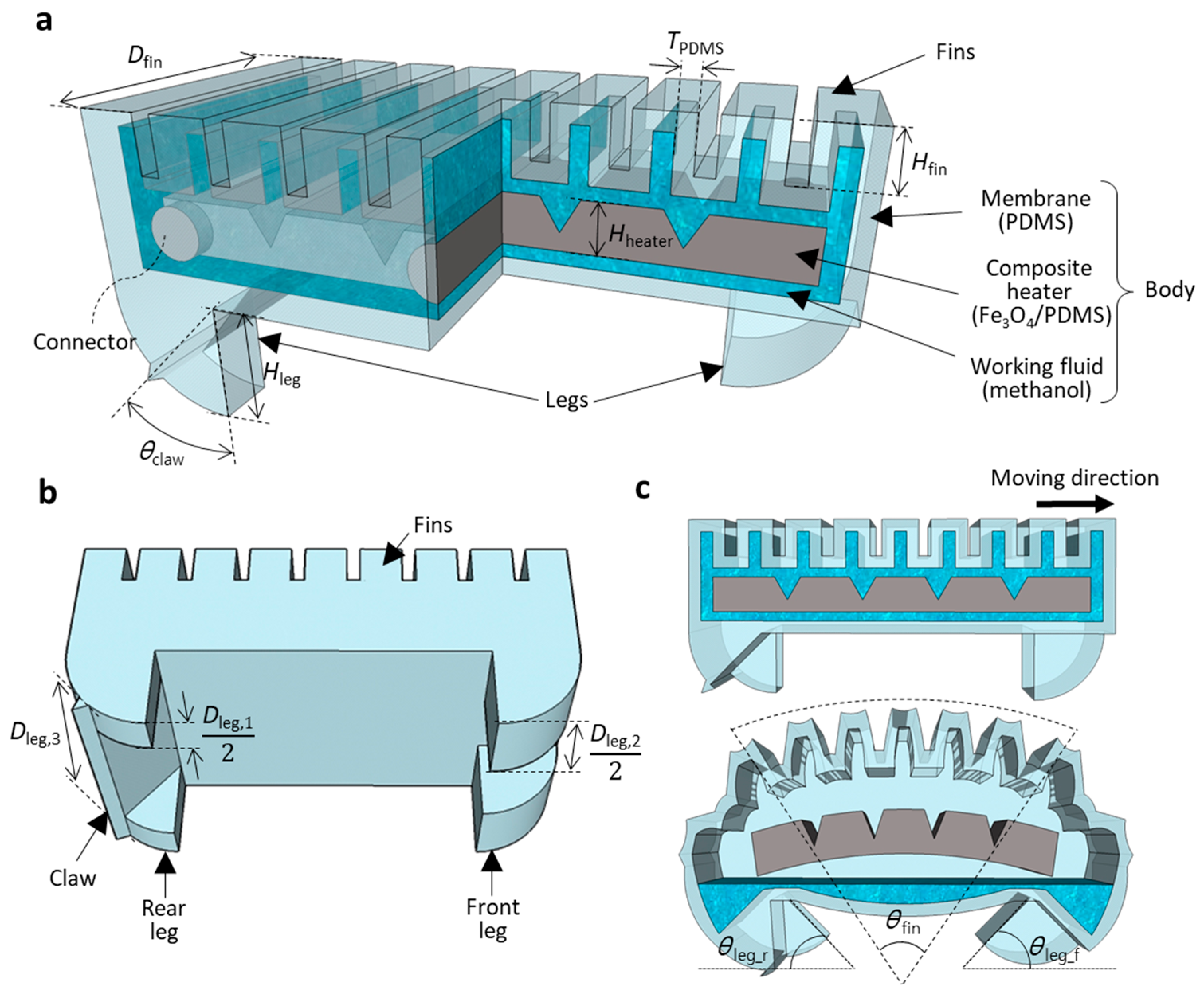
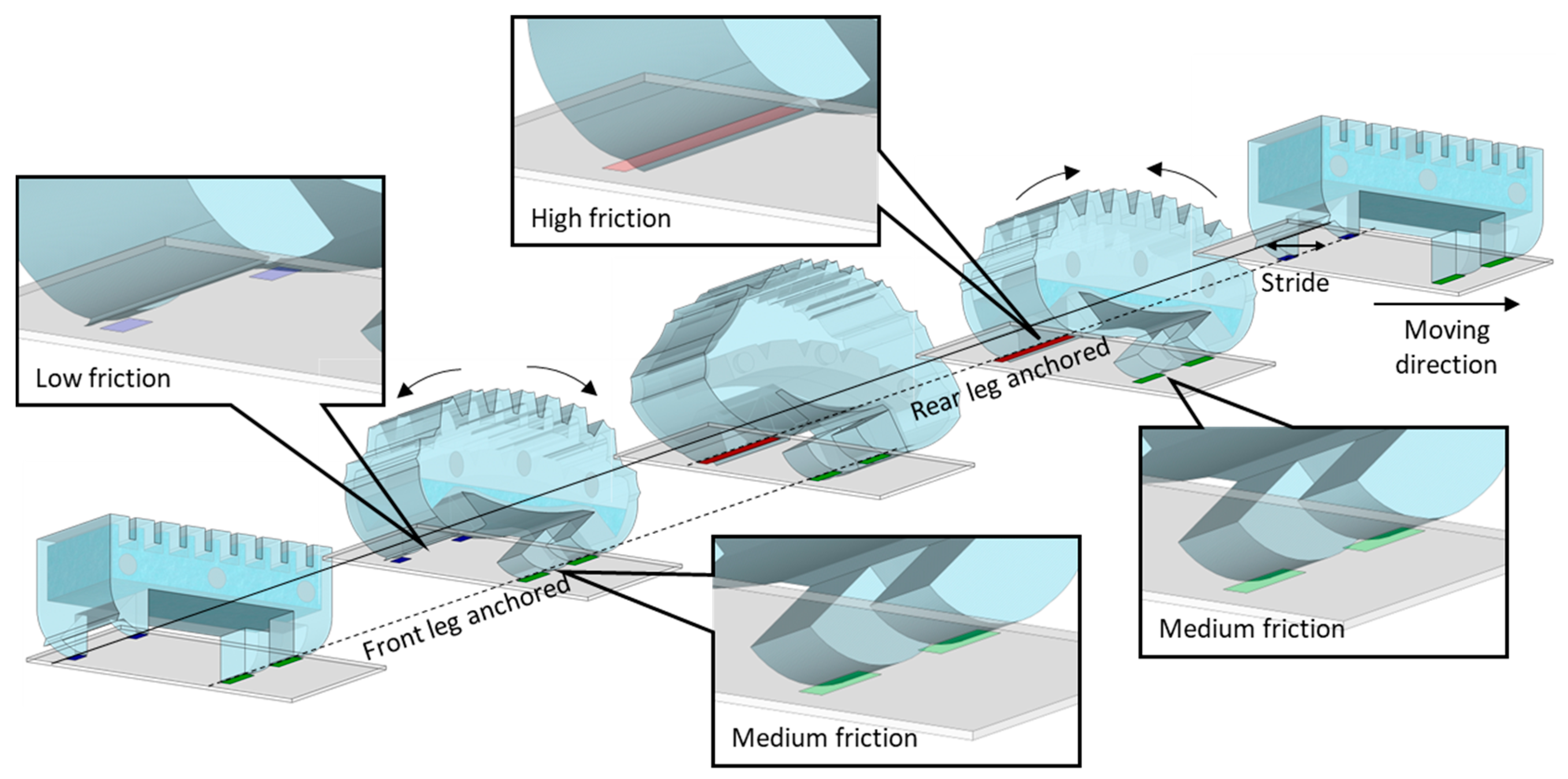
2.1. Design
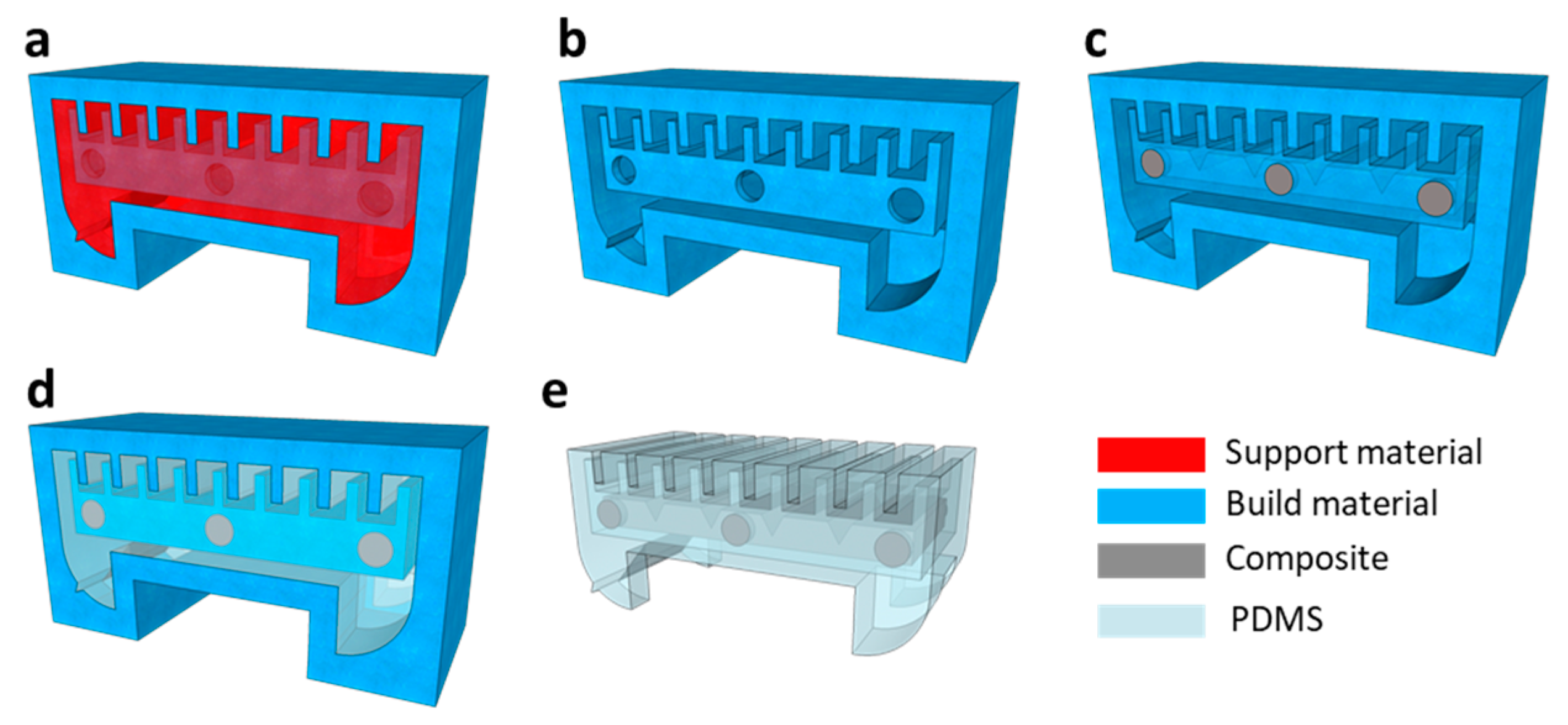
2.2. Fabrication
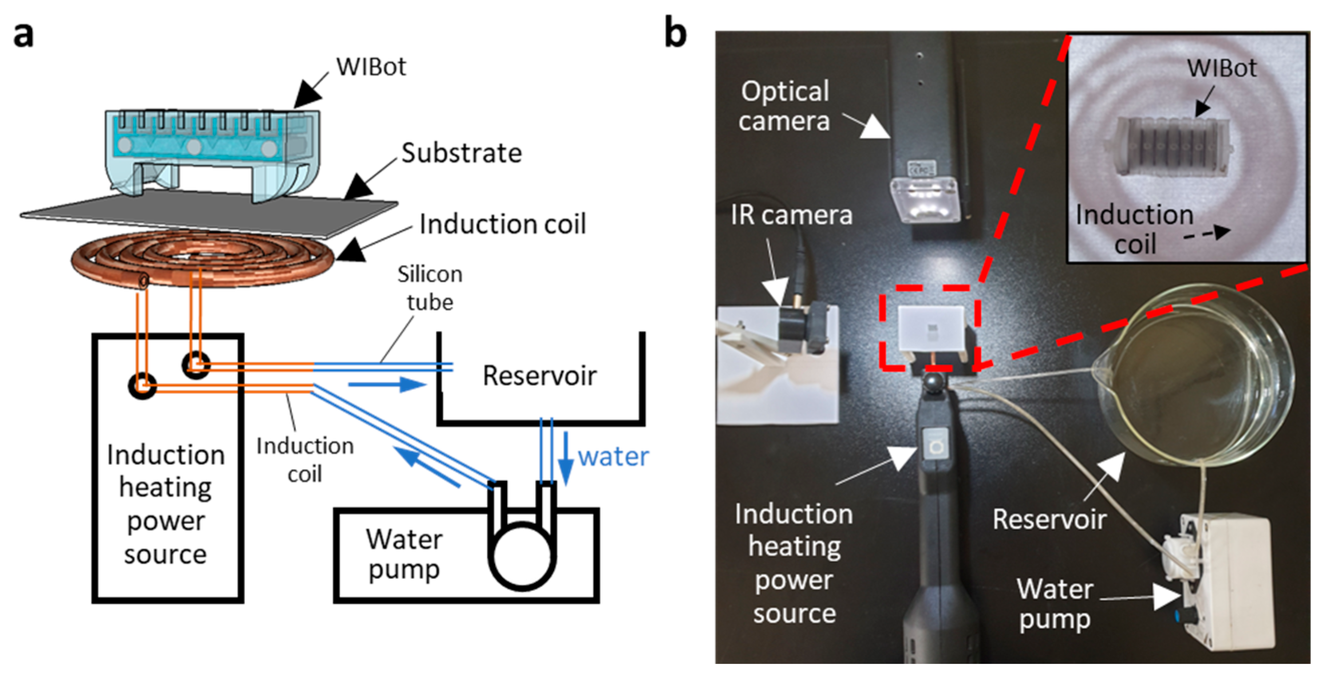
2.3. Measurement Setup
3. Results and Discussion
4. Conclusions
Supplementary Materials
Author Contributions
Funding
Data Availability Statement
Conflicts of Interest
References
- Darmawan, B.A.; Lee, S.B.; Nguyen, V.D.; Go, G.; Nguyen, K.T.; Lee, H.-S.; Nan, M.; Hong, A.; Kim, C.-S.; Li, H.; et al. Self-folded microrobot for active drug delivery and rapid ultrasound-triggered drug release. Sens. Actuator B Chem. 2020, 324, 128752. [Google Scholar] [CrossRef]
- Li, H.; Go, G.; Ko, S.Y.; Park, J.-O.; Park, S. Magnetic actuated pH-responsive hydrogel-based soft micro-robot for targeted drug delivery. Smart Mater. Struct. 2016, 25, 027001. [Google Scholar] [CrossRef]
- Hamed, A.; Tang, S.C.; Ren, H.; Squires, A.; Payne, C.; Masamune, K.; Tang, G.; Mohammadpour, J.; Tse, Z.T.H. Advances in Haptics, Tactile Sensing, and Manipulation for Robot-Assisted Minimally Invasive Surgery, Noninvasive Surgery, and Diagnosis. J. Robot. 2012, 2012, 412816. [Google Scholar] [CrossRef] [Green Version]
- Perrard, C.; Andreff, N. Control of a Team of Micro-Robots for Non-Invasive Medical Applications. In Proceedings of the 6th National Conference on Control Architectures of Robots, Grenoble, France, 24–25 May 2011. [Google Scholar]
- Abdelaal, A.E.; Mathur, P.; Salcudean, S.E. Robotics in vivo: A perspective on human–robot interaction in surgical robotics. Annu. Rev. Control Robot. Auton. Syst. 2020, 3, 221–242. [Google Scholar] [CrossRef] [Green Version]
- Liang, C.; Wang, Y.; Yao, T.; Zhu, B. A shape memory alloy–actuated soft crawling robot based on adaptive differential friction and enhanced antagonistic configuration. J. Intell. Mater. Syst. Struct. 2020, 31, 1920–1934. [Google Scholar] [CrossRef]
- Liu, T.L.; Wen, X.; Kung, Y.C.; Chiou, P.Y. Fabrication Strategy for Micro Soft Robotics with Semiconductor Devices Integration. In Proceedings of the 2017 IEEE 30th International Conference on Micro Electro Mechanical Systems (MEMS), Las Vegas, NV, USA, 22–26 January 2017. [Google Scholar]
- Kawun, P.; Leahy, S.; Lai, Y. A thin PDMS nozzle/diffuser micropump for biomedical applications. Sens. Actuators A Phys. 2016, 249, 149–154. [Google Scholar] [CrossRef]
- Gul, J.Z.; Sajid, M.; Rehman, M.M.; Siddiqui, G.U.; Shah, I.; Kim, K.-H.; Lee, J.-W.; Choi, K.H. 3D printing for soft robotics—A review. Sci. Technol. Adv. Mater. 2018, 19, 243–262. [Google Scholar] [CrossRef] [Green Version]
- Wang, Q.; Wu, Z.; Huang, J.; Du, Z.; Yue, Y.; Chen, D.; Li, D.; Su, B. Integration of sensing and shape-deforming capabilities for a bioinspired soft robot. Compos. Part B Eng. 2021, 223, 109116. [Google Scholar] [CrossRef]
- Wu, P.; Jiangbei, W.; Yanqiong, F. The Structure, Design, and Closed-Loop Motion Control of a Differential Drive Soft Robot. Soft Robot. 2017, 5, 71–80. [Google Scholar] [CrossRef]
- Sheng, X.; Xu, H.; Zhang, N.; Ding, N.; Zhu, X.; Gu, G. Multi-material 3D printing of caterpillar-inspired soft crawling robots with the pneumatically bellow-type body and anisotropic friction feet. Sens. Actuators A Phys. 2020, 316, 112398. [Google Scholar] [CrossRef]
- Yu, M.; Yang, W.; Yu, Y.; Cheng, X.; Jiao, Z. A Crawling Soft Robot Driven by Pneumatic Foldable Actuators Based on Miura-Ori. Actuators 2020, 9, 26. [Google Scholar] [CrossRef] [Green Version]
- Thomas, S.; Germano, P.; Martinez, T.; Perriard, Y. An untethered mechanically-intelligent inchworm robot powered by a shape memory alloy oscillator. Sens. Actuators A Phys. 2021, 332, 113115. [Google Scholar] [CrossRef]
- Koh, J.S.; Cho, K.J. Omega-Shaped Inchworm-Inspired Crawling Robot with Large-Index-and-Pitch (LIP) SMA Spring Actuators. IEEE-ASME Trans. Mechatron. 2013, 18, 419–429. [Google Scholar] [CrossRef]
- Yang, Y.; Tse, Y.A.; Zhang, Y.; Kan, Z.; Wang, M.Y. A Low-Cost Inchworm-Inspired Soft Robot Driven by Supercoiled Polymer Artificial Muscle. In Proceedings of the 2019 2nd IEEE International Conference on Soft Robotics (RoboSoft), Seoul, Republic of Korea, 14–18 April 2019. [Google Scholar]
- Tang, X.; Li, K.; Liu, Y.; Zhou, D.; Zhao, J. A soft crawling robot driven by single twisted and coiled actuator. Sens. Actuators A Phys. 2019, 291, 80–86. [Google Scholar] [CrossRef]
- Liang, J.; Wu, Y.; Shao, Z.; Yim, J.K.; Xu, R.; Song, Y.; Qi, M.; Zhong, J.; Zhang, M.; Wang, X.; et al. Manipulating the Moving Trajectory of Insect-Scale Piezoelectric Soft Robots by Frequency. In Proceedings of the 2019 IEEE 32nd International Conference on Micro Electro Mechanical Systems (MEMS), Seoul, Republic of Korea, 27–31 January 2019. [Google Scholar]
- Park, T.; Cha, Y. Soft mobile robot inspired by animal-like running motion. Sci. Rep. 2019, 9, 14700. [Google Scholar] [CrossRef] [Green Version]
- Tolley, M.T.; Shepherd, R.F.; Karpelson, M.; Bartlett, N.W.; Galloway, K.C.; Wehner, M.; Nunes, R.; Whitesides, G.M.; Wood, R.J. An Untethered Jumping Soft Robot. In Proceedings of the 2014 IEEE/RSJ International Conference on Intelligent Robots and Systems, Chicago, IL, USA, 14–18 September 2014. [Google Scholar]
- Wehner, M.; Truby, R.L.; Fitzgerald, D.J.; Mosadegh, B.; Whitesides, G.M.; Lewis, J.A.; Wood, R.J. An integrated design and fabrication strategy for entirely soft, autonomous robots. Nature 2016, 536, 451–455. [Google Scholar] [CrossRef] [Green Version]
- Yin, C.; Wei, F.; Fu, S.; Zhai, Z.; Ge, Z.; Yao, L.; Jiang, M.; Liu, M. Visible Light-Driven Jellyfish-like Miniature Swimming Soft Robot. ACS Appl. Mater. Interfaces 2021, 13, 47147–47154. [Google Scholar] [CrossRef]
- Rogóż, M.; Dradrach, K.; Xuan, C.; Wasylczyk, P. A Millimeter-Scale Snail Robot Based on a Light-Powered Liquid Crystal Elastomer Continuous Actuator. Macromol. Rapid Commun. 2019, 40, 1900279. [Google Scholar] [CrossRef]
- Niu, H.; Feng, R.; Xie, Y.; Jiang, B.; Sheng, Y.; Yu, Y.; Baoyin, H.; Zeng, X. MagWorm: A Biomimetic Magnet Embedded Worm-Like Soft Robot. Soft Robot. 2021, 8, 507–518. [Google Scholar] [CrossRef]
- Hua, D.; Liu, X.; Sun, S.; Sotelo, M.A.; Li, Z.; Li, W. A Magnetorheological Fluid-Filled Soft Crawling Robot with Magnetic Actuation. IEEE/ASME Trans. Mechatron. 2020, 25, 2700–2710. [Google Scholar] [CrossRef]
- Wu, Z.; Wang, Q.; Huang, J.; Yue, Y.; Chen, D.; Shi, Y.; Su, B. The soft NdFeB/Ecoflex composites for soft robot with a considerable magnetostimulated shrinkability. Compos. Sci. Technol. 2022, 217, 109129. [Google Scholar] [CrossRef]
- Ze, Q.; Wu, S.; Nishikawa, J.; Dai, J.; Sun, Y.; Leanza, S.; Zemelka, C.; Novelino, L.S.; Paulino, G.H.; Zhao, R.R. Soft robotic origami crawler. Sci. Adv. 2022, 8, eabm7834. [Google Scholar] [CrossRef] [PubMed]
- Lee, S.; Jung, W.; Ko, K.; Hwang, Y. Wireless Micro Soft Actuator without Payloads Using 3D Helical Coils. Micromachines 2022, 13, 799. [Google Scholar] [CrossRef] [PubMed]
- Mirvakili, S.M.; Sim, D.; Hunter, I.W.; Langer, R. Actuation of untethered pneumatic artificial muscles and soft robots using magnetically induced liquid-to-gas phase transitions. Sci. Robot. 2020, 5, eaaz4239. [Google Scholar] [CrossRef] [PubMed]
- Kang, K.; Oh, S.; Yi, H.; Han, S.; Hwang, Y. Fabrication of truly 3D microfluidic channel using 3D-printed soluble mold. Biomicrofluidics 2018, 12, 014105. [Google Scholar] [CrossRef]
- Yang, X.; Chang, L.; Pérez-Arancibia, N.O. An 88-milligram insect-scale autonomous crawling robot driven by a catalytic artificial muscle. Sci. Robot. 2020, 5, eaba0015. [Google Scholar] [CrossRef]
- Müller, A.; Wapler, M.C.; Wallrabe, U. A quick and accurate method to determine the Poisson’s ratio and the coefficient of thermal expansion of PDMS. Soft Matter 2019, 15, 779–784. [Google Scholar] [CrossRef] [Green Version]
- Camino, G.; Lomakin, S.M.; Lazzari, M. Polydimethylsiloxane thermal degradation Part 1. Kinetic aspects. Polymer 2001, 42, 2395–2402. [Google Scholar] [CrossRef]
- Kim, T.K.; Kim, J.K.; Jeong, O.C. Measurement of nonlinear mechanical properties of PDMS elastomer. Microelectron. Eng. 2011, 88, 1982–1985. [Google Scholar] [CrossRef]
- Nojiri, S.; Mizushima, K.; Suzuki, Y.; Tsuji, T.; Watanabe, T. Development of Contact Area Variable Surface for Manipulation Requiring Sliding. In Proceedings of the 2019 2nd IEEE International Conference on Soft Robotics (RoboSoft), Seoul, Republic of Korea, 14–18 April 2019. [Google Scholar]
- The Dow Chemical Company. SYLGARD™ 184 Silicone Elastomer. Available online: www.dow.com/content/dam/dcc/documents/en-us/productdatasheet (accessed on 3 January 2023).


| Symbol | Description | Value |
|---|---|---|
| TPDMS | PDMS thickness | 0.2 mm |
| Hfin | Fin height | 0.6 mm |
| Dfin | Fin depth | 3.5 mm |
| N | Number of fins | 9 |
| Hheater | Heater height | 0.6 mm |
| θclaw | Claw angle | 30° |
| Hleg | Leg height | 1.2 mm |
| Dleg,1 | Leg depth 1 | 1.2 mm |
| Dleg,2 | Leg depth 2 | 2.3 mm |
| Dleg,3 | Leg depth 3 | 3.5 mm |
Disclaimer/Publisher’s Note: The statements, opinions and data contained in all publications are solely those of the individual author(s) and contributor(s) and not of MDPI and/or the editor(s). MDPI and/or the editor(s) disclaim responsibility for any injury to people or property resulting from any ideas, methods, instructions or products referred to in the content. |
© 2023 by the authors. Licensee MDPI, Basel, Switzerland. This article is an open access article distributed under the terms and conditions of the Creative Commons Attribution (CC BY) license (https://creativecommons.org/licenses/by/4.0/).
Share and Cite
Jung, W.; Lee, S.; Hwang, Y. Wireless Inchworm-like Compact Soft Robot by Induction Heating of Magnetic Composite. Micromachines 2023, 14, 162. https://doi.org/10.3390/mi14010162
Jung W, Lee S, Hwang Y. Wireless Inchworm-like Compact Soft Robot by Induction Heating of Magnetic Composite. Micromachines. 2023; 14(1):162. https://doi.org/10.3390/mi14010162
Chicago/Turabian StyleJung, Woojun, Seonghyeon Lee, and Yongha Hwang. 2023. "Wireless Inchworm-like Compact Soft Robot by Induction Heating of Magnetic Composite" Micromachines 14, no. 1: 162. https://doi.org/10.3390/mi14010162