
2-Dimensional (2D) Beam Steering-Antenna Using Active PRS for 5G Applications
 , and
, and
Abstract
:1. Introduction
2. Design Methodology
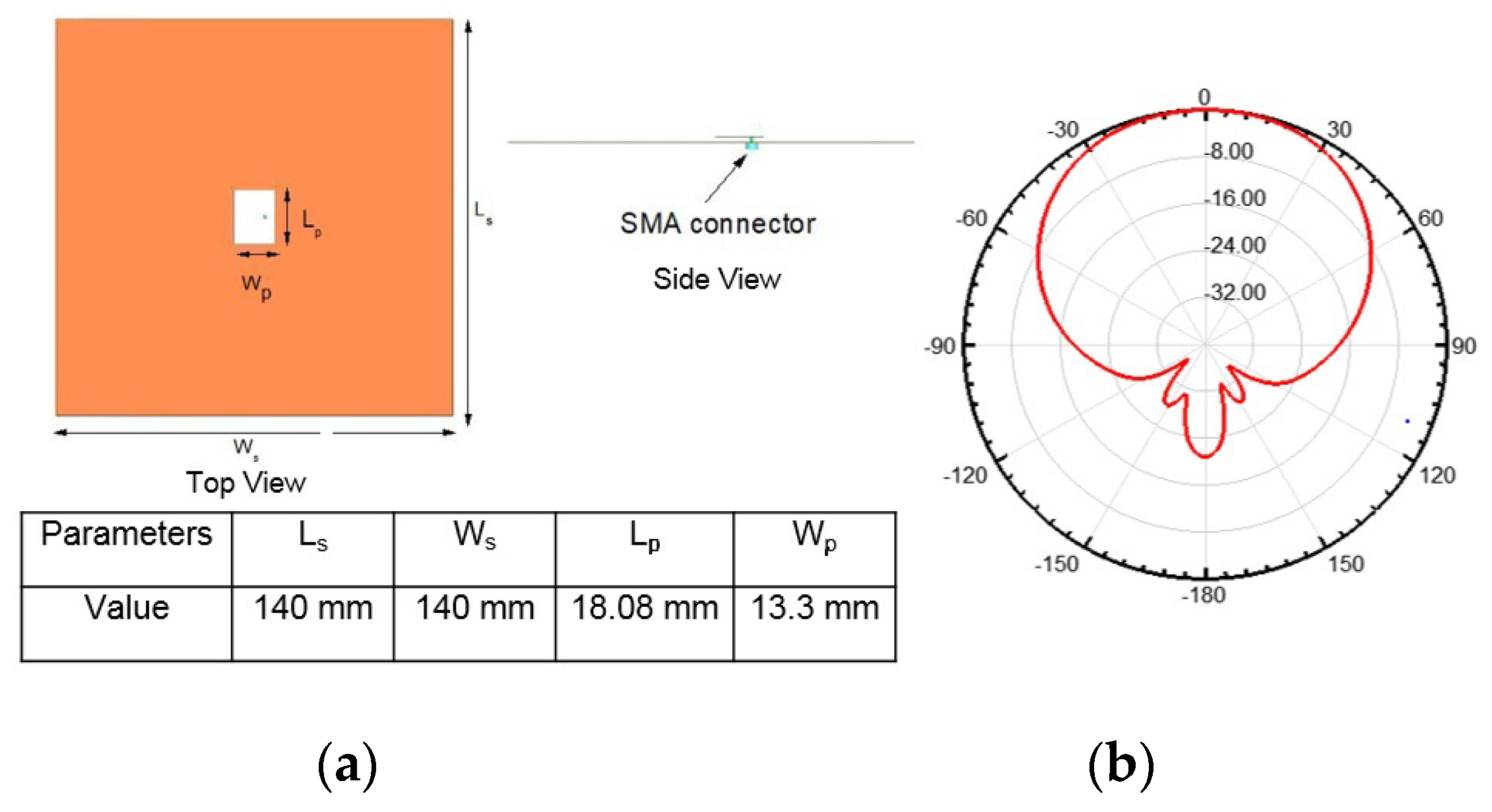
- Antenna Design
- II.
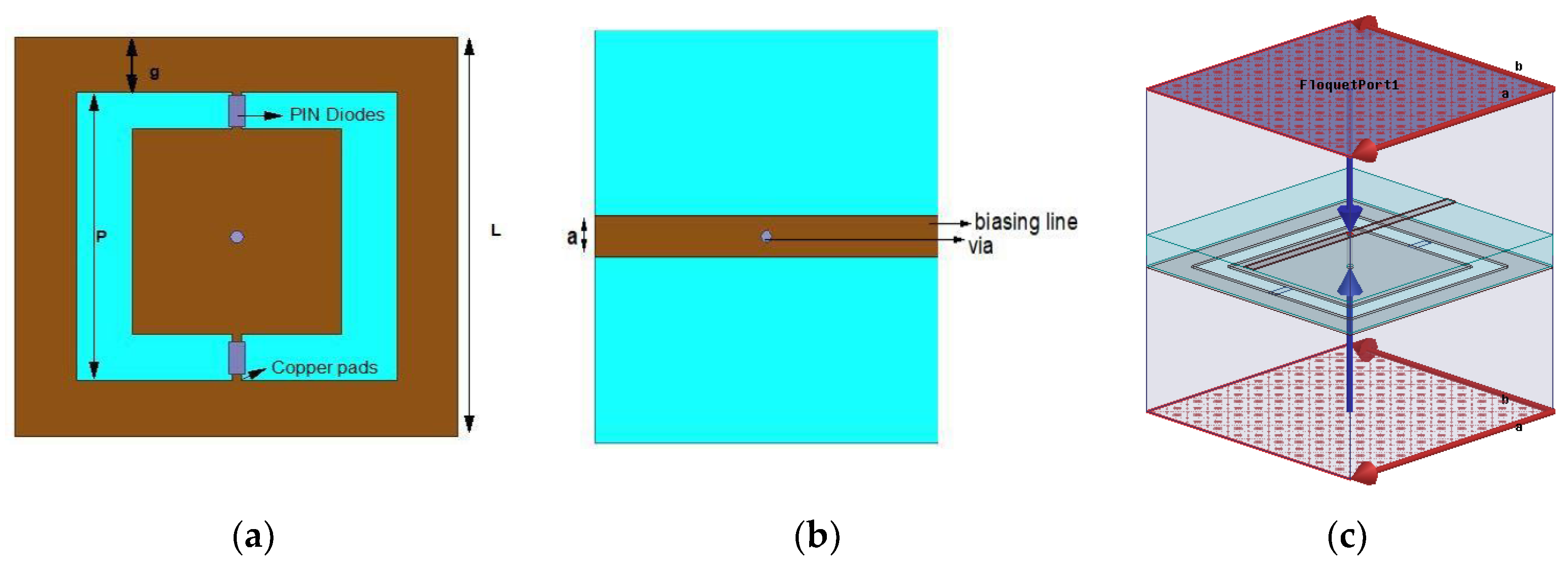
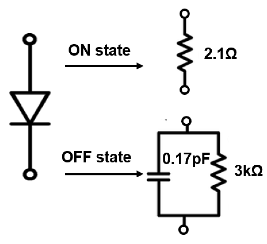
- Proposed Unit Cell
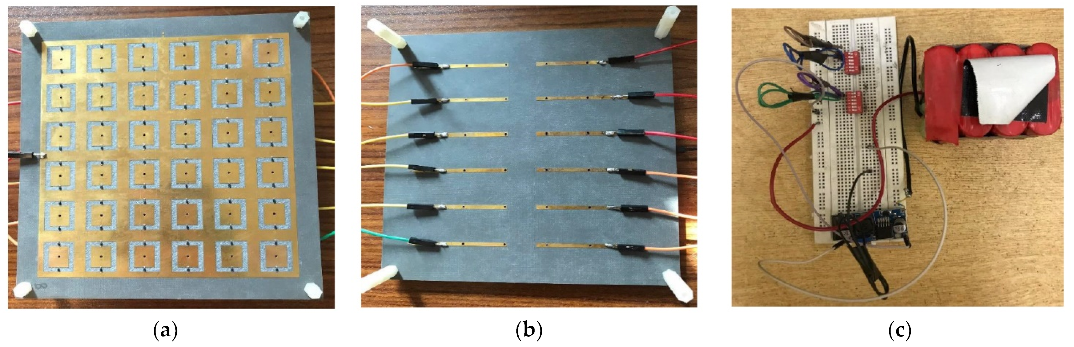
3. Results and Discussions
4. Conclusions
Author Contributions
Funding
Data Availability Statement
Acknowledgments
Conflicts of Interest
References
- Zhu, X.-C.; Hong, W.; Wu, K.; Tang, H.-J.; Hao, Z.-C.; Chen, J.-X.; Yang, G.-Q. A novel reflective surface with polarization rotation characteristic. IEEE Antennas Wirel. Propag. Lett. 2013, 12, 968–971. [Google Scholar] [CrossRef]
- Liu, S.; Cui, T.J.; Zhang, L.; Xu, Q.; Wang, Q.; Wan, X.; Gu, J.Q.; Tang, W.X.; Qi, M.Q.; Han, J.G.; et al. Convolution operations on coding metasurface to reach flexible and continuous controls of terahertz beams. Adv. Sci. 2016, 3, 1600156. [Google Scholar] [CrossRef] [PubMed]
- Li, H.; Wang, G.; Liang, J.; Gao, X.; Hou, H.; Jia, X. Single-layer focusing gradient metasurface for ultrathin planar lens antenna application. IEEE Trans. Antennas Propag. 2017, 65, 1452–1457. [Google Scholar] [CrossRef]
- Alwareth, H.; Ibrahim, I.M.; Zakaria, Z.; Al-Gburi, A.J.A.; Ahmed, S.; Nasser, Z.A. A Wideband High-Gain Microstrip Array Antenna Integrated with Frequency-Selective Surface for Sub-6 GHz 5G Applications. Micromachines 2022, 13, 1215. [Google Scholar] [CrossRef] [PubMed]
- Melouki, N.; Hocini, A.; Fegriche, F.Z.; PourMohammadi, P.; Naseri, H.; Iqbal, A.; Denidni, T.A. High-Gain Wideband Circularly Polarised Fabry–Perot Resonator Array Antenna Using a Single-Layered Pixelated PRS for Millimetre-Wave Applications. Micromachines 2022, 13, 1658. [Google Scholar] [CrossRef] [PubMed]
- Al-Gburi, A.J.A.; Ibrahim, I.B.M.; Zeain, M.Y.; Zakaria, Z. Compact Size and High Gain of CPW-Fed UWB Strawberry Artistic Shaped Printed Monopole Antennas Using FSS Single Layer Reflector. IEEE Access 2020, 8, 92697–92707. [Google Scholar] [CrossRef]
- Gu, C.; Gao, S.; Sanz-Izquierdo, B.; Parker, E.A.; Li, W.; Yang, X.; Cheng, Z. Frequency-agile beam-switchable antenna. IEEE Trans. Antennas Propag. 2017, 65, 3819–3826. [Google Scholar] [CrossRef] [Green Version]
- Li, J.; Zeng, Q.; Liu, R.; Denidni, T.A. A Compact Dual-Band Beam-Sweeping Antenna Based on Active Frequency Selective Surfaces. IEEE Trans. Antennas Propag. 2017, 65, 1542–1549. [Google Scholar] [CrossRef]
- Gu, C.; Izquierdo, B.S.; Gao, S.; Batchelor, J.C.; Parker, E.A.; Qin, F.; Wei, G.; Li, J.; Xu, J. Dual-Band Electronically Beam-Switched Antenna Using Slot Active Frequency Selective Surface. IEEE Trans. Antennas Propag. 2017, 65, 1393–1398. [Google Scholar] [CrossRef]
- Leingthone, M.M.; Hakem, N. A reconfigurable beam swhitching antenna using active cylindrical fss structure. In Proceedings of the 2017 IEEE International Symposium on Antennas and Propagation & USNC/URSI National Radio Science Meeting, San Diego, CA, USA, 9–14 July 2017; pp. 2339–2340. [Google Scholar]
- Bouslama, M.; Herzi, R.; Denidni, A.G.A.T.A. 3D Reconfigurable Frequency Selective Surface antenna for beam-switching applications. In Proceedings of the 2017 Mediterranean Microwave Symposium (MMS), Marseille, France, 28–30 November 2017; pp. 1–2. [Google Scholar]
- Leingthone, M.M.; Hakem, N. Reconfigurable Switched-Beam Antenna Using Cylindrical Bow Tie FSS Window. In Proceedings of the 2018 IEEE International Symposium on Antennas and Propagation & USNC/URSI National Radio Science Meeting, Boston, MA, USA, 8–13 July 2018; pp. 1851–1852. [Google Scholar]
- Zhang, L.; Wu, Q.; Denidni, T.A. Electronically Radiation Pattern Steerable Antennas Using Active Frequency Selective Surfaces. IEEE Trans. Antennas Propag. 2013, 61, 6000–6007. [Google Scholar] [CrossRef]
- Li, J.; Denidni, T.A.; Zeng, Q.; Zhang, W. Active frequency selective surfaces for beam switching applications. In Proceedings of the 2015 IEEE 6th International Symposium on Microwave, Antenna, Propagation, and EMC Technologies (MAPE), Shanghai, China, 28–30 October 2015; pp. 816–818. [Google Scholar]
- Saeed, M.A.; Ahmad, M.; Nwajana, A.; Rehman, M.U.; Sohaib, M.A.; Naseer, A. Coaxial Feed Ultra-Wideband Microstrip Antenna for Medical Applications. In Proceedings of the 2022 International Conference on Electrical, Computer and Energy Technologies (ICECET), Prague, Czech Republic, 20–22 July 2022; pp. 1–4. [Google Scholar]
- Luo, Z.; Long, J.; Chen, X.; Sievenpiper, D. Electrically tunable metasurface absorber based on dissipating behavior of embedded varactors. Appl. Phys. Lett. 2016, 109, 1516–1519. [Google Scholar] [CrossRef]
- Debogovic, T.; Perruisseau-Carrier, J. Array-fed partially reflective surface antenna with independent scanning and beamwidth dynamic control. IEEE Trans. Antennas Propag. 2014, 62, 446–449. [Google Scholar] [CrossRef]
- Guzman-Quiros, R.; Weily, A.R.; Gomez-Tornero, J.L.; Guo, Y.J. A Fabry–Perot antenna with two-dimensional electronic beam scanning. IEEE Trans. Antennas Propag. 2016, 64, 1536–1541. [Google Scholar] [CrossRef]
- Ji, L.Y.; Guo, Y.J.; Qin, P.Y.; Gong, S.-X.; Mittra, R. A reconfigurable partially reflective surface (PRS) antenna for beam steering. IEEE Trans. Antennas Propag. 2015, 63, 2387–2395. [Google Scholar] [CrossRef]
- Xie, P.; Wang, G.; Li, H.; Liang, J. A dual-polarized two-dimensional beam-steering Fabry–Pérot cavity antenna with a reconfigurable partially reflecting surface. IEEE Antennas Wirel. Propag. Lett. 2017, 16, 2370–2374. [Google Scholar] [CrossRef]
- Pozar, D.M. Microwave Engineering, 4th ed.; Wiley: New York, NY, USA, 2011. [Google Scholar]
- Shoaib, N. Vector Network Analyzer (VNA) Measurements and Uncertainty Assessment; Springer Nature Switzerland AG: Cham, Switzerland, 2017; Volume 1, pp. 1–82. Available online: https://link.springer.com/book/10.1007/978-3-319-44772-8 (accessed on 2 December 2022).
- Ji, L.; Zhang, Z.; Liu, N. A Two-Dimensional Beam-Steering Partially Reflective Surface (PRS) Antenna Using a Reconfigurable FSS Structure. IEEE Antennas Wirel. Propag. Lett. 2019, 18, 1076–1080. [Google Scholar] [CrossRef]
- Ji, L.-Y.; Qin, P.-Y.; Li, J.-Y.; Zhang, L.-X. 1-D Electronic Beam Steering Partially Reflective Surface Antenna. IEEE Access 2019, 7, 115959–115965. [Google Scholar] [CrossRef]


| Parameters | L | P | G | a |
|---|---|---|---|---|
| Value | 20 | 14.5 | 2.25 | 2 |
| State | Sec-01 | Sec-02 | Sec-03 | Sec-04 | Beam Direction |
|---|---|---|---|---|---|
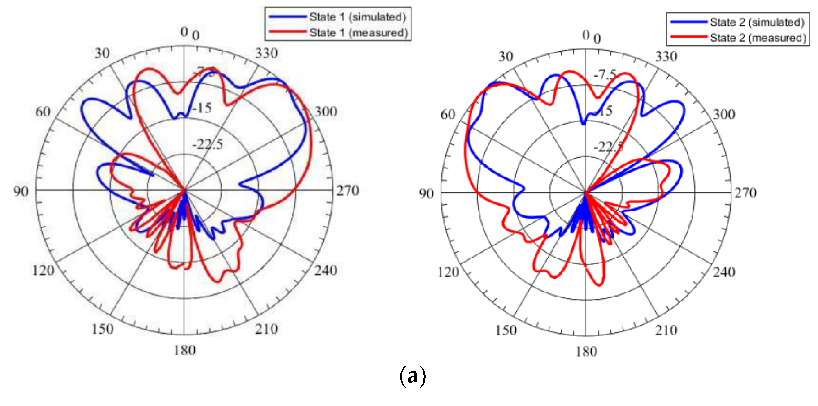
| 1 | ON | OFF | OFF | ON | φ/θ = 90°/42° (Azimuth Plane) |
| 2 | OFF | ON | ON | OFF | φ/θ = 90°/−42° (Azimuth Plane) |
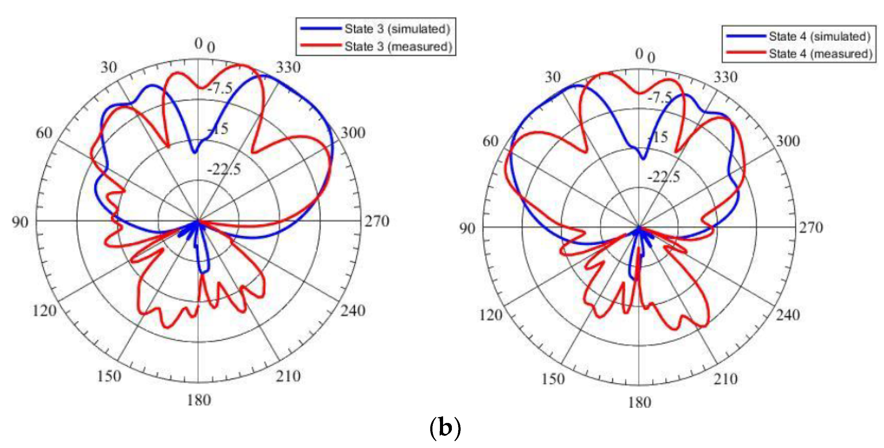
| 3 | ON | ON | OFF | OFF | φ/θ = 0°/46° (Elevation Plane) |
| 4 | OFF | OFF | ON | ON | φ/θ = 0°/−45° (Elevation Plane) |
| 5 | OFF | OFF | OFF | OFF | Broadside |
| State | Simulated Gain | Measured Gain |
|---|---|---|
| 1 | 10.5 dB | 9.1 dB |
| 2 | 10.2 dB | 10.2 dB |
| 3 | 8.83 dB | 8.8 dB |
| 4 | 8.81 dB | 8.7 dB |
Disclaimer/Publisher’s Note: The statements, opinions and data contained in all publications are solely those of the individual author(s) and contributor(s) and not of MDPI and/or the editor(s). MDPI and/or the editor(s) disclaim responsibility for any injury to people or property resulting from any ideas, methods, instructions or products referred to in the content. |
© 2022 by the authors. Licensee MDPI, Basel, Switzerland. This article is an open access article distributed under the terms and conditions of the Creative Commons Attribution (CC BY) license (https://creativecommons.org/licenses/by/4.0/).
Share and Cite
Nadeem, M.; Shoaib, N.; Raza, A.; Saeed, W.; Shoaib, I.; Shoaib, S. 2-Dimensional (2D) Beam Steering-Antenna Using Active PRS for 5G Applications. Micromachines 2023, 14, 110. https://doi.org/10.3390/mi14010110
Nadeem M, Shoaib N, Raza A, Saeed W, Shoaib I, Shoaib S. 2-Dimensional (2D) Beam Steering-Antenna Using Active PRS for 5G Applications. Micromachines. 2023; 14(1):110. https://doi.org/10.3390/mi14010110
Chicago/Turabian StyleNadeem, Misha, Nosherwan Shoaib, Aimen Raza, Warda Saeed, Imran Shoaib, and Sultan Shoaib. 2023. "2-Dimensional (2D) Beam Steering-Antenna Using Active PRS for 5G Applications" Micromachines 14, no. 1: 110. https://doi.org/10.3390/mi14010110