
Hierarchical Self-Assembly of Dipolar ZnO Nanoparticles and Microdroplets


Abstract
:1. Introduction
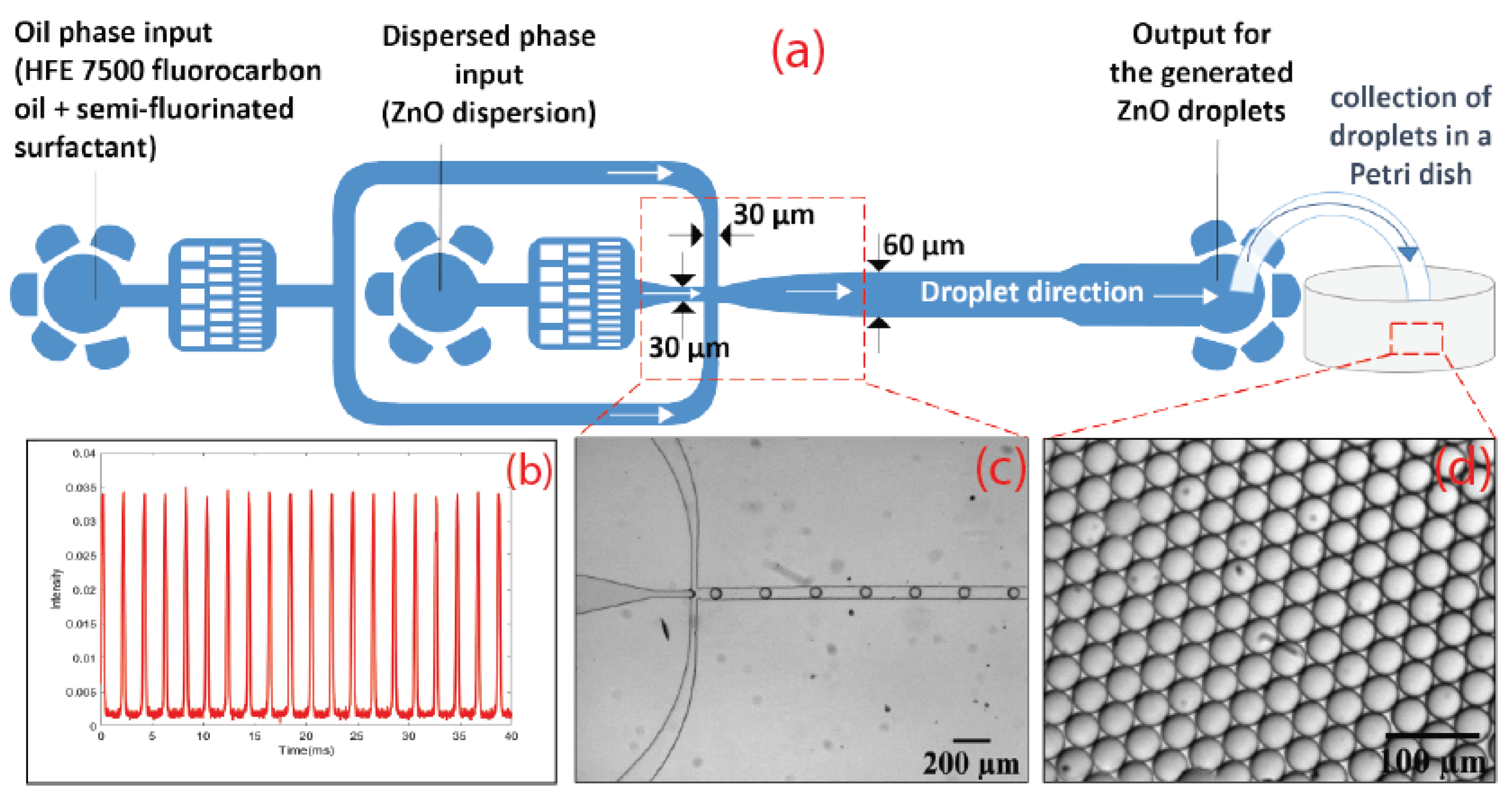
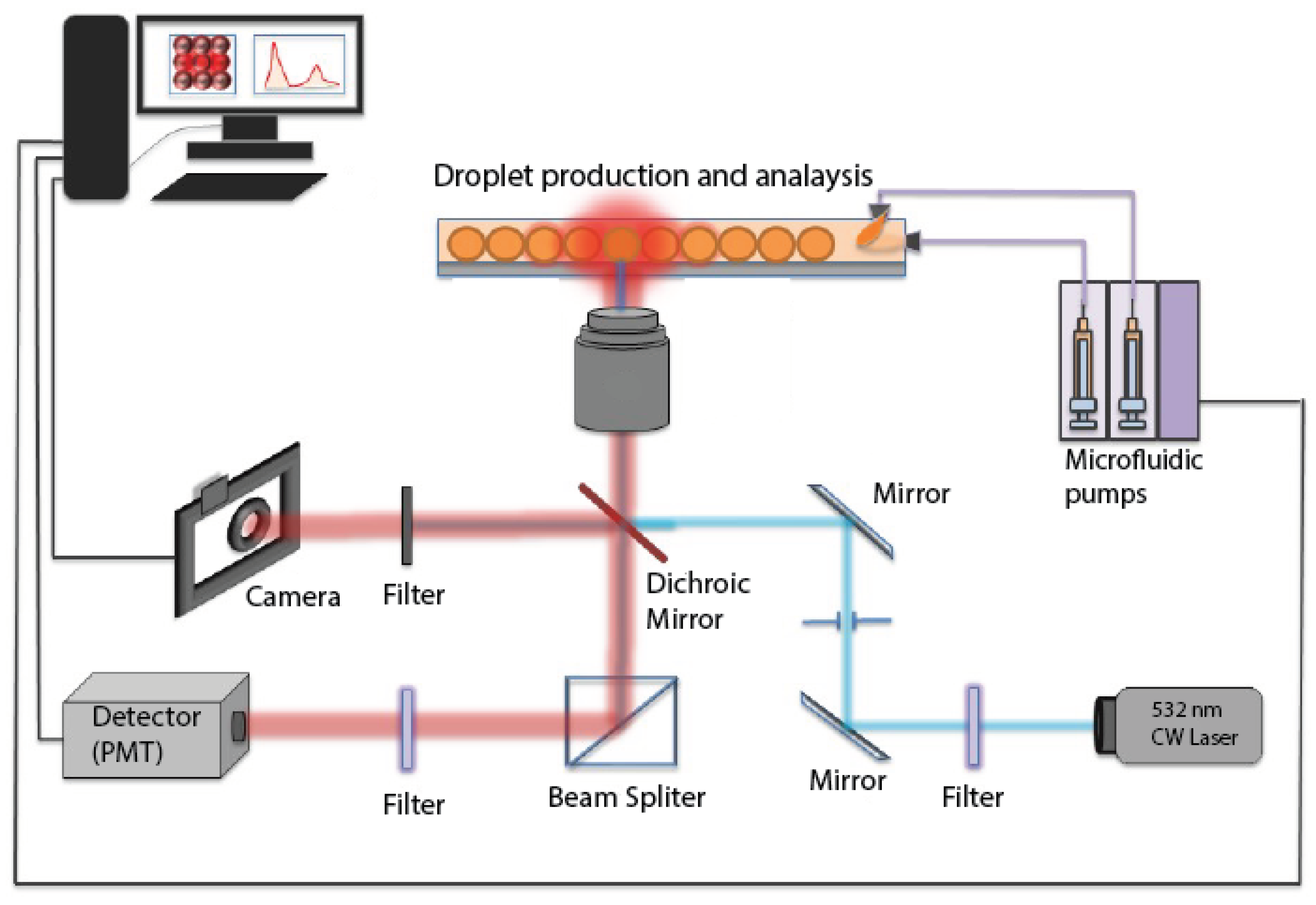
2. Methodology
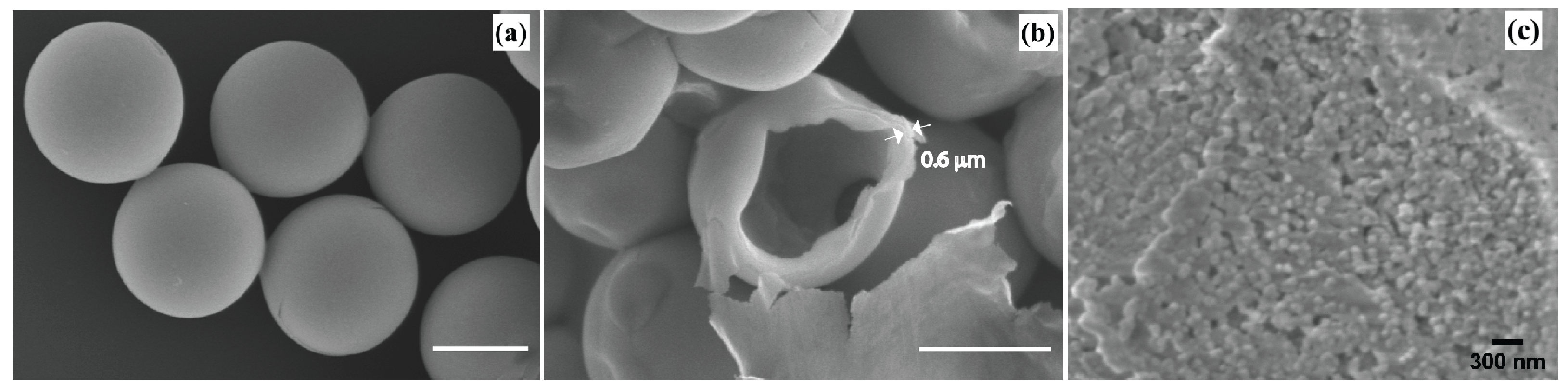
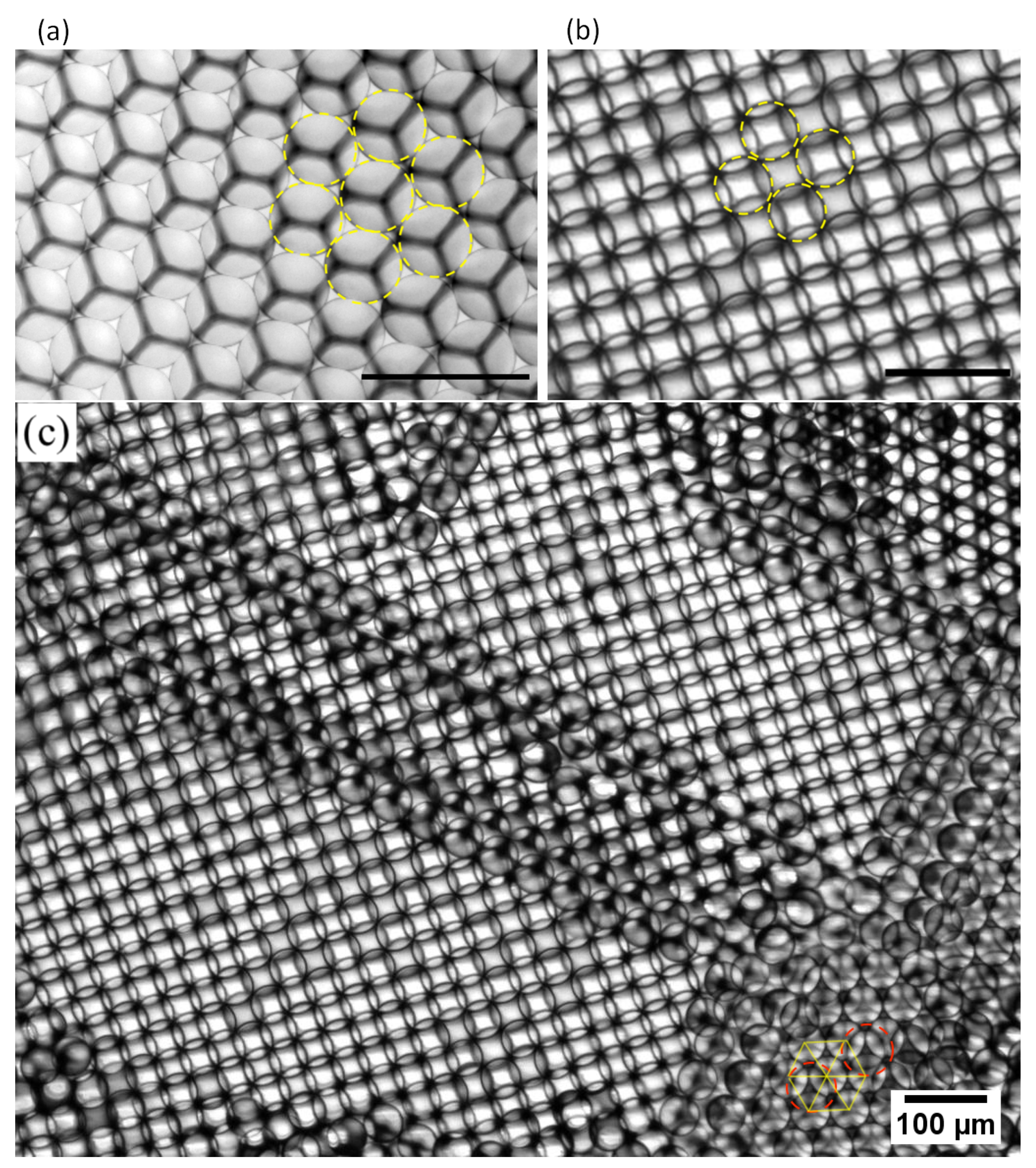
3. Results and Discussion
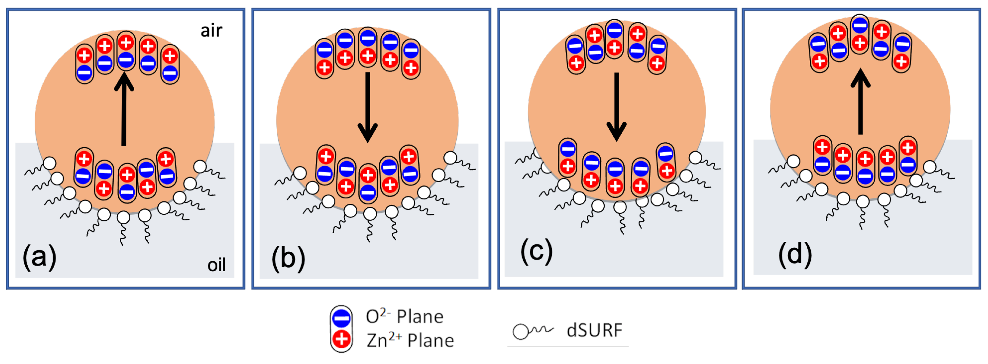
3.1. First Experimental Evidence of the Formation of Dipolar Droplets
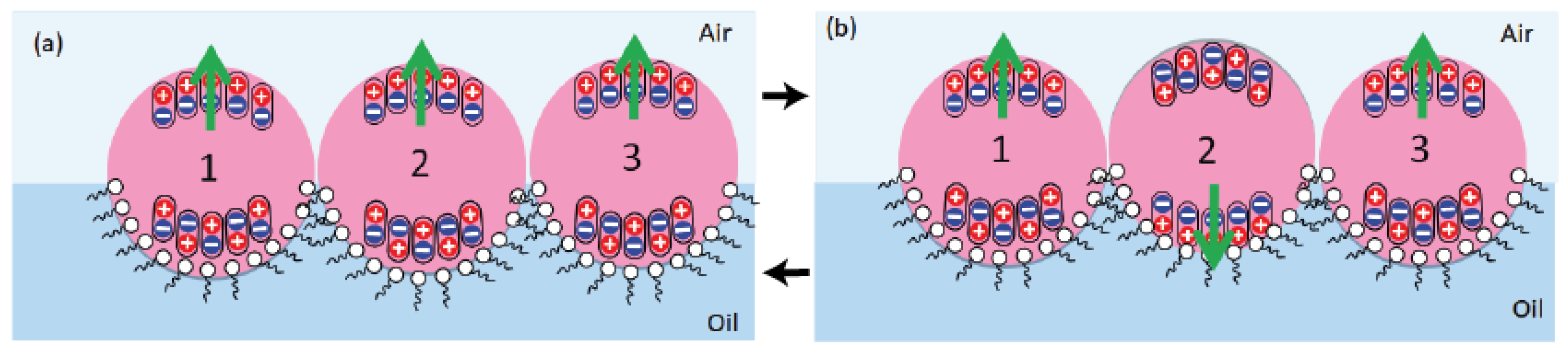
3.2. Broken Spherical Symmetry of Droplets at the Oil/Air Interface
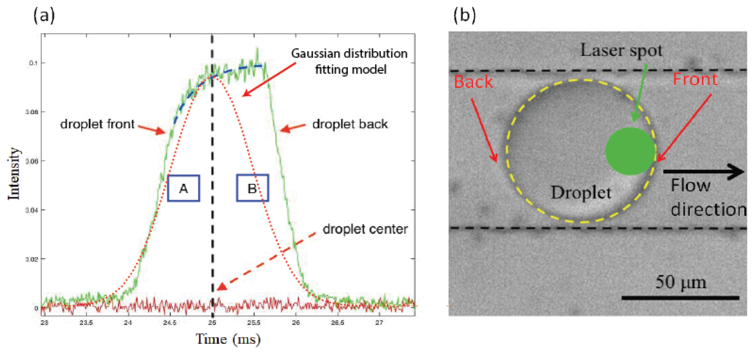
3.3. Flow-Driven Droplet Electric Dipole Model (Fedd Model)
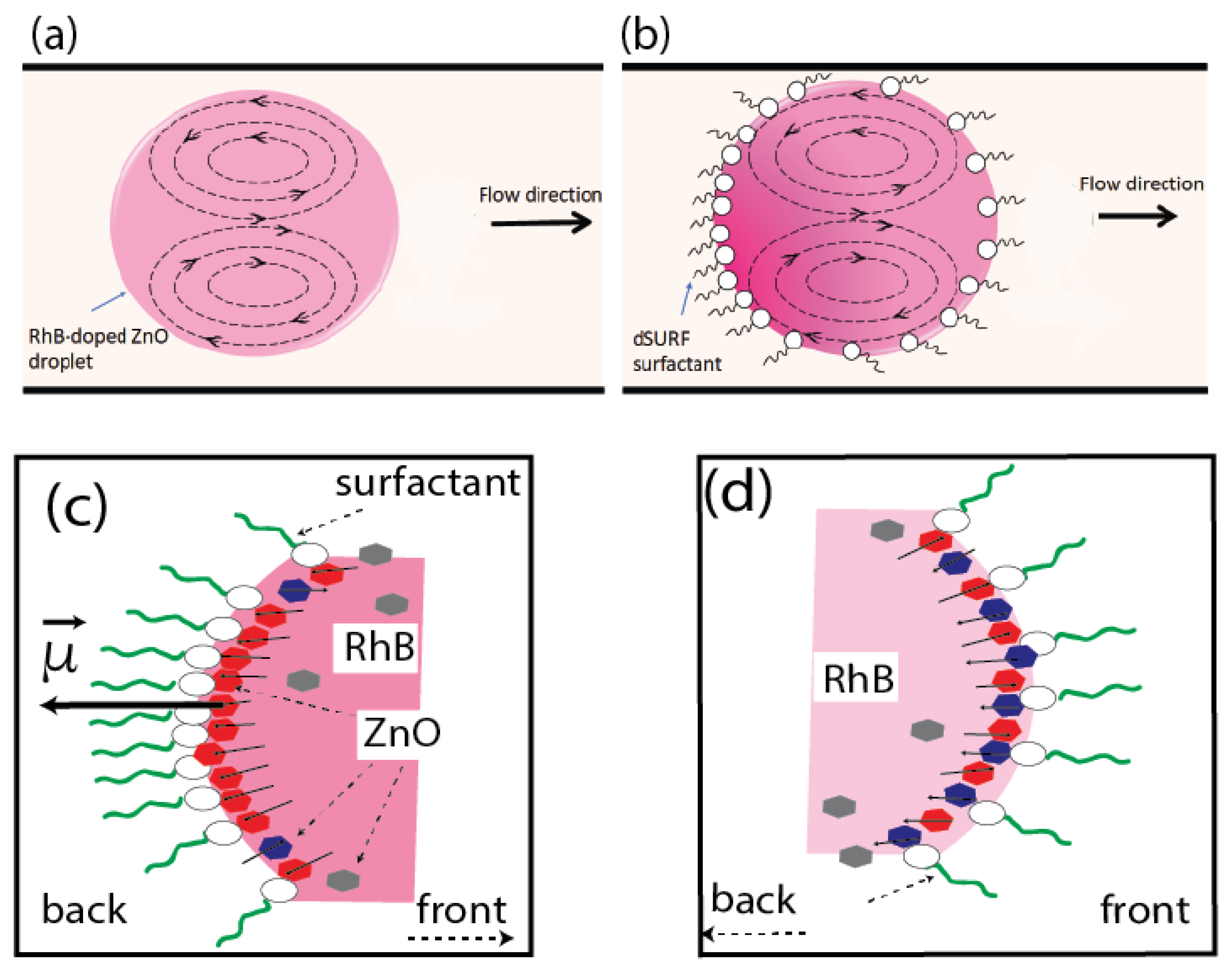
3.4. Effect of Addition of Rhodamine B Molecules
4. Conclusions
Supplementary Materials
Author Contributions
Funding
Conflicts of Interest
References
- Cöelfen, H.; Antonietti, M. Mesocrystals and Nonclassical Crystallization; John Wiley & Sons: Hoboken, NJ, USA, 2008. [Google Scholar]
- Cöelfen, H.; Mann, S. Higher-order organization by mesoscale self-assembly and transformation of hybrid nanostructures. Angew. Chem. Int. Ed. 2003, 42, 2350–2365. [Google Scholar] [CrossRef] [PubMed]
- Sushko, M.L. Understanding the driving forces for crystal growth by oriented attachment through theory and simulations. J. Mater. Res. 2019, 34, 1–14. [Google Scholar] [CrossRef]
- Pacholski, C.; Kornowski, A.; Weller, H. Self-assembly of ZnO: From nanodots to nanorods. Angew. Chem. Int. Ed. 2002, 41, 1188–1191. [Google Scholar] [CrossRef]
- Andreassen, J.P.; Lewis, A.E. Classical and nonclassical theories of crystal growth. In New Perspectives on Mineral Nucleation and Growth; Springer: Berlin/Heidelberg, Germany, 2017; pp. 137–154. [Google Scholar]
- Bergström, L.; Sturm, E.V.; Salazar-Alvarez, G.; Cölfen, H. Mesocrystals in biominerals and colloidal arrays. Accounts Chem. Res. 2015, 48, 1391–1402. [Google Scholar] [CrossRef]
- Jung, J.S.; Hwang, N.M. Non-Classical Crystallization of Thin Films and Nanostructures in CVD Process. In Chemical Vapor Deposition: Recent Advances and Applications in Optical, Solar Cells and Solid State Devices; InTech: Rijeka, Croatia, 2016; p. 23. [Google Scholar]
- Hwang, N.M. Non-Classical Crystallization of Thin Films and Nanostructures in CVD and PVD Processes; Springer: Berlin/Heidelberg, Germany, 2016; Volume 60. [Google Scholar]
- Lee, E.J.; Ribeiro, C.; Longo, E.; Leite, E.R. Oriented attachment: An effective mechanism in the formation of anisotropic nanocrystals. J. Phys. Chem. B 2005, 109, 20842–20846. [Google Scholar] [CrossRef] [PubMed]
- Liu, Y.; Geng, H.; Qin, X.; Yang, Y.; Zeng, Z.; Chen, S.; Lin, Y.; Xin, H.; Song, C.; Zhu, X.; et al. Oriented Attachment Revisited: Does a Chemical Reaction Occur? Matter 2019, 1, 690–704. [Google Scholar] [CrossRef]
- Meldrum, F.C.; Cölfen, H. Controlling mineral morphologies and structures in biological and synthetic systems. Chem. Rev. 2008, 108, 4332–4432. [Google Scholar] [CrossRef]
- Lv, W.; He, W.; Wang, X.; Niu, Y.; Cao, H.; Dickerson, J.H.; Wang, Z. Understanding the oriented-attachment growth of nanocrystals from an energy point of view: A review. Nanoscale 2014, 6, 2531–2547. [Google Scholar] [CrossRef]
- Wang, A.; Huang, J.; Yan, Y. Hierarchical molecular self-assemblies: Construction and advantages. Soft Matter 2014, 10, 3362–3373. [Google Scholar] [CrossRef]
- Busch, S.; Dolhaine, H.; DuChesne, A.; Heinz, S.; Hochrein, O.; Laeri, F.; Podebrad, O.; Vietze, U.; Weiland, T.; Kniep, R. Biomimetic morphogenesis of fluorapatite-gelatin composites: Fractal growth, the question of intrinsic electric fields, core/shell assemblies, hollow spheres and reorganization of denatured collagen. Eur. J. Inorg. Chem. 1999, 1999, 1643–1653. [Google Scholar] [CrossRef]
- Busch, S.; Schwarz, U.; Kniep, R. Chemical and structural investigations of biomimetically grown fluorapatite–gelatin composite aggregates. Adv. Funct. Mater. 2003, 13, 189–198. [Google Scholar] [CrossRef]
- Liu, Z.; Wen, X.; Wu, X.; Gao, Y.; Chen, H.; Zhu, J.; Chu, P. Intrinsic dipole-field-driven mesoscale crystallization of core- shell ZnO mesocrystal microspheres. J. Am. Chem. Soc. 2009, 131, 9405–9412. [Google Scholar] [CrossRef] [PubMed]
- Tampo, H.; Fons, P.; Yamada, A.; Kim, K.K.; Shibata, H.; Matsubara, K.; Yoshikawa, H.; Kanie, H.; Niki, S. Determination of crystallographic polarity of ZnO bulk crystals and epilayers. Phys. Status Solidi C 2006, 3, 1018–1021. [Google Scholar] [CrossRef]
- Dai, S.; Park, H.S. Surface effects on the piezoelectricity of ZnO nanowires. J. Mech. Phys. Solids 2013, 61, 385–397. [Google Scholar] [CrossRef]
- Xiang, H.; Yang, J.; Hou, J.; Zhu, Q. Piezoelectricity in ZnO nanowires: A first-principles study. Appl. Phys. Lett. 2006, 89, 223111. [Google Scholar] [CrossRef]
- Yufei, Z.; Zhiyou, G.; Xiaoqi, G.; Dongxing, C.; Yunxiao, D.; Hongtao, Z. First-principles of wurtzite ZnO (0001) and (0001) surface structures. J. Semicond. 2010, 31, 082001. [Google Scholar] [CrossRef]
- Ludi, B.; Niederberger, M. Zinc oxide nanoparticles: Chemical mechanisms and classical and non-classical crystallization. Dalton Trans. 2013, 42, 12554–12568. [Google Scholar] [CrossRef]
- Massidda, S.; Resta, R.; Posternak, M.; Baldereschi, A. Polarization and dynamical charge of ZnO within different one-particle schemes. Phys. Rev. B 1995, 52, R16977. [Google Scholar] [CrossRef]
- Bernardini, F.; Fiorentini, V.; Vanderbilt, D. Spontaneous polarization and piezoelectric constants of III-V nitrides. Phys. Rev. B 1997, 56, R10024. [Google Scholar] [CrossRef]
- Noel, Y.; Zicovich-Wilson, C.; Civalleri, B.; D’arco, P.; Dovesi, R. Polarization properties of ZnO and BeO: An ab initio study through the Berry phase and Wannier functions approaches. Phys. Rev. B 2001, 65, 014111. [Google Scholar] [CrossRef]
- Ozgur, U.; Alivov, Y.I.; Liu, C.; Teke, A.; Reshchikov, M.A.; Dogan, S.; Avrutin, V.; Cho, S.J.; Morkoç, H. A comprehensive review of ZnO materials and devices. J. Appl. Phys. 2005, 98, 041301. [Google Scholar] [CrossRef]
- Ghifari, N.; Cinquin, B.; Chahboun, A.; El Abed, A.I. Rhodamine B Doped ZnO Monodisperse Microcapsules: Droplet-Based Synthesis, Dynamics and Self-Organization of ZnO Nanoparticles and Dye Molecules. Nanomaterials 2020, 10, 2351. [Google Scholar] [CrossRef] [PubMed]
- Eggleton, C.D.; Tsai, T.M.; Stebe, K.J. Tip streaming from a drop in the presence of surfactants. Phys. Rev. Lett. 2001, 87, 048302. [Google Scholar] [CrossRef] [PubMed]
- Baroud, C.N.; Gallaire, F.; Dangla, R. Dynamics of microfluidic droplets. Lab A Chip 2010, 10, 2032–2045. [Google Scholar] [CrossRef]
- Baret, J.C. Surfactants in droplet-based microfluidics. Lab A Chip 2012, 12, 422–433. [Google Scholar] [CrossRef]
- Duffy, D.C.; McDonald, J.C.; Schueller, O.J.; Whitesides, G.M. Rapid prototyping of microfluidic systems in poly (dimethylsiloxane). Anal. Chem. 1998, 70, 4974–4984. [Google Scholar] [CrossRef]
- Zukas, B.G.; Gupta, N.R. Interphase Synthesis of Zinc Oxide Nanoparticles in a Droplet Flow Reactor. Ind. Eng. Chem. Res. 2017, 56, 7184–7191. [Google Scholar] [CrossRef]
- Wang, J.; Jin, M.; He, T.; Zhou, G.; Shui, L. Microfluidic induced controllable microdroplets assembly in confined channels. Micromachines 2015, 6, 1331–1345. [Google Scholar] [CrossRef]
- Hayat, Z.; El Abed, A. High-Throughput Optofluidic Acquisition of Microdroplets in Microfluidic Systems. Micromachines 2018, 9, 183. [Google Scholar] [CrossRef]
- Baret, J.C.; Kleinschmidt, F.; El Harrak, A.; Griffiths, A.D. Kinetic aspects of emulsion stabilization by surfactants: A microfluidic analysis. Langmuir 2009, 25, 6088–6093. [Google Scholar] [CrossRef]


Publisher’s Note: MDPI stays neutral with regard to jurisdictional claims in published maps and institutional affiliations. |
© 2022 by the authors. Licensee MDPI, Basel, Switzerland. This article is an open access article distributed under the terms and conditions of the Creative Commons Attribution (CC BY) license (https://creativecommons.org/licenses/by/4.0/).
Share and Cite
Ghifari, N.; Bennacer, R.; Chahboun, A.; El Abed, A.I. Hierarchical Self-Assembly of Dipolar ZnO Nanoparticles and Microdroplets. Micromachines 2022, 13, 1522. https://doi.org/10.3390/mi13091522
Ghifari N, Bennacer R, Chahboun A, El Abed AI. Hierarchical Self-Assembly of Dipolar ZnO Nanoparticles and Microdroplets. Micromachines. 2022; 13(9):1522. https://doi.org/10.3390/mi13091522
Chicago/Turabian StyleGhifari, Najla, Rachid Bennacer, Adil Chahboun, and Abdel I. El Abed. 2022. "Hierarchical Self-Assembly of Dipolar ZnO Nanoparticles and Microdroplets" Micromachines 13, no. 9: 1522. https://doi.org/10.3390/mi13091522