
New Compact Antenna Array for MIMO Internet of Things Applications

 ,
,
Abstract
:1. Introduction
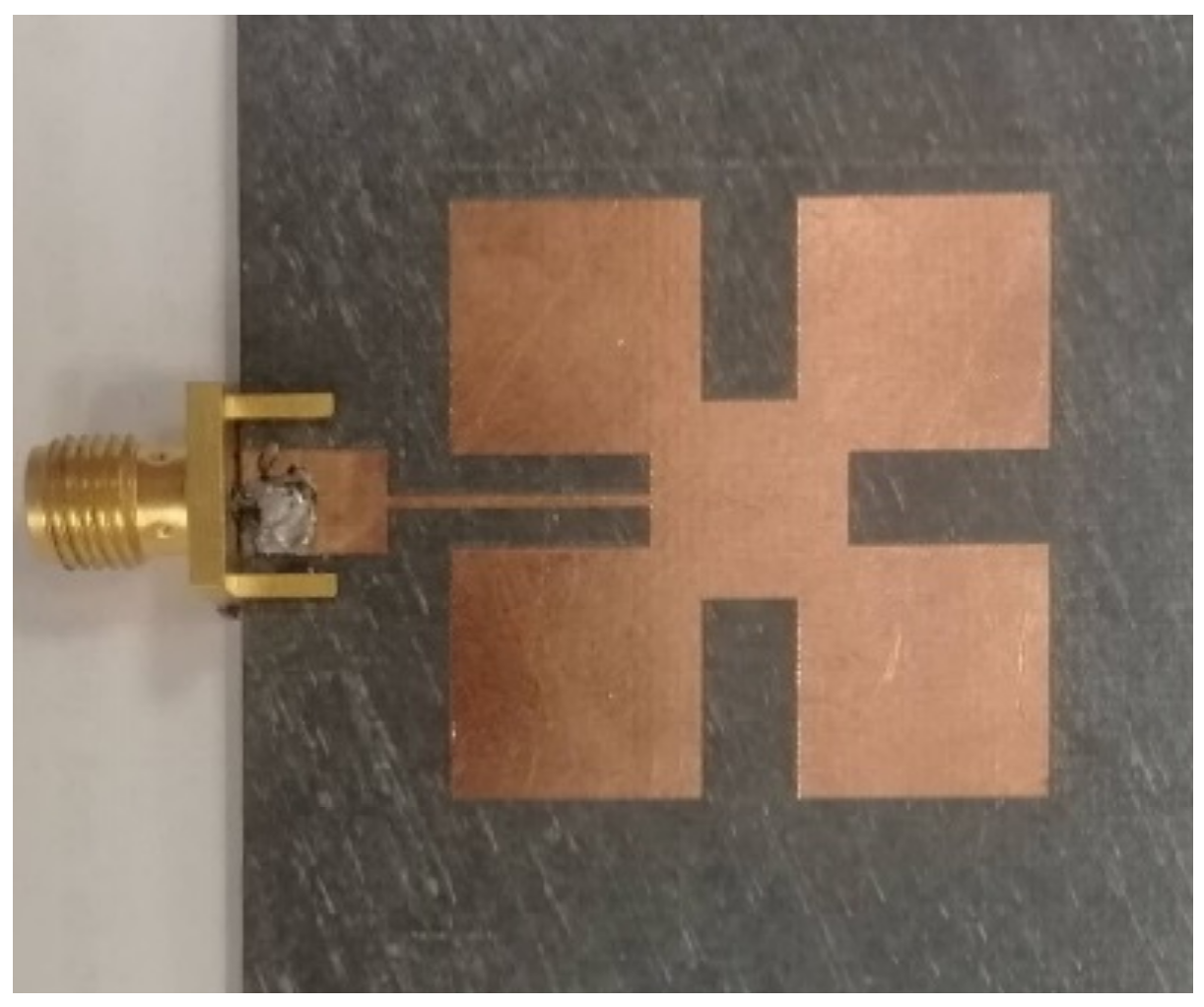
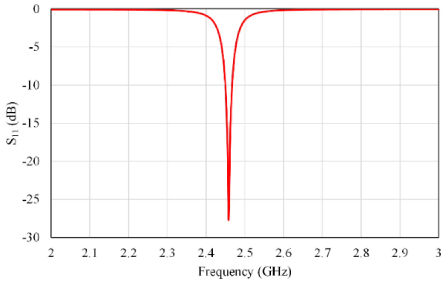
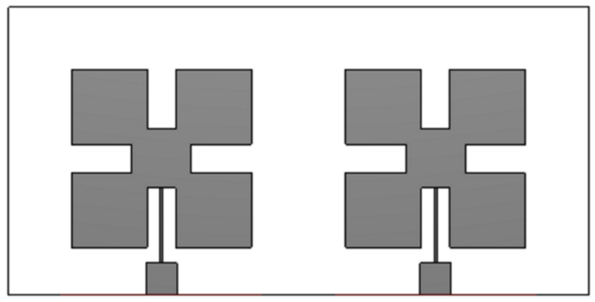
2. Single Element Antenna
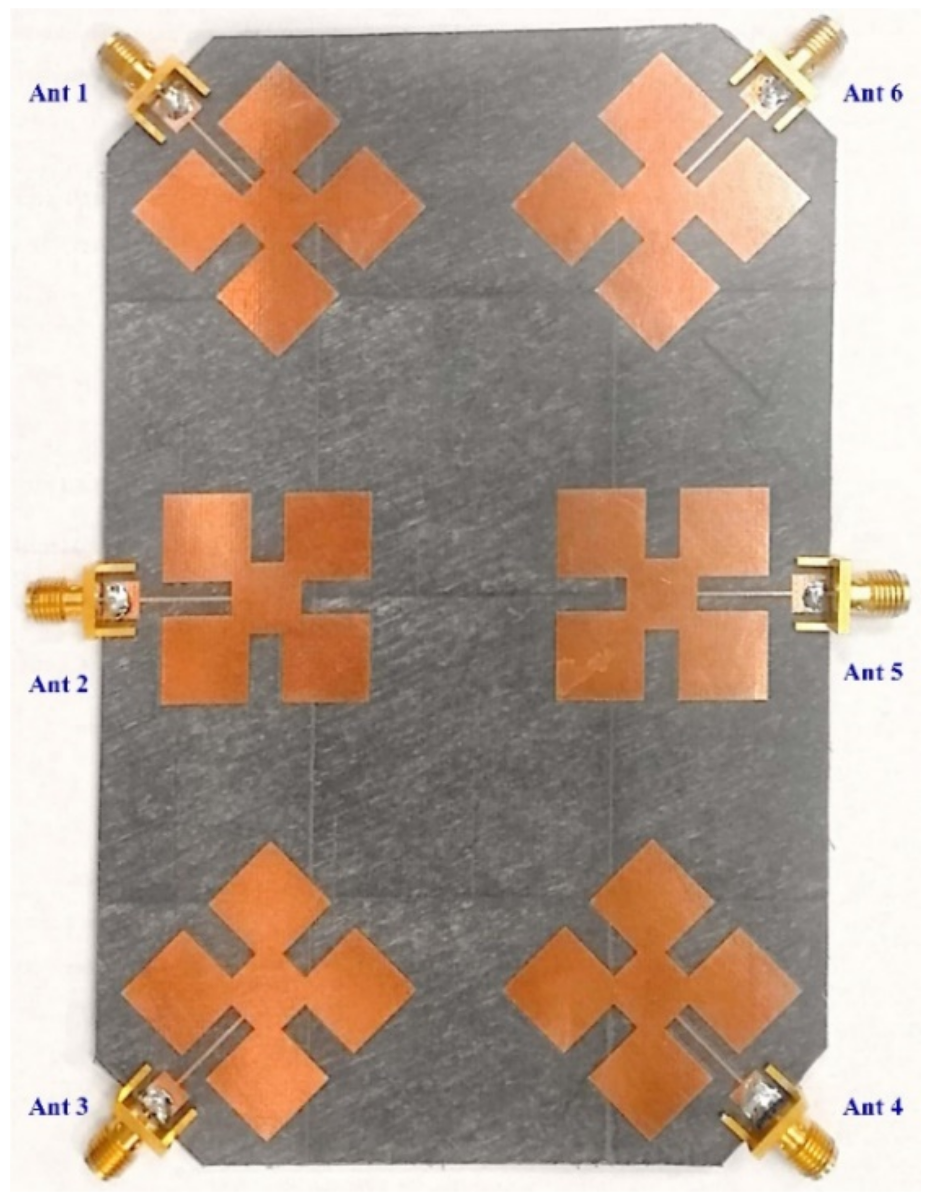
3. Proposed Array Structure
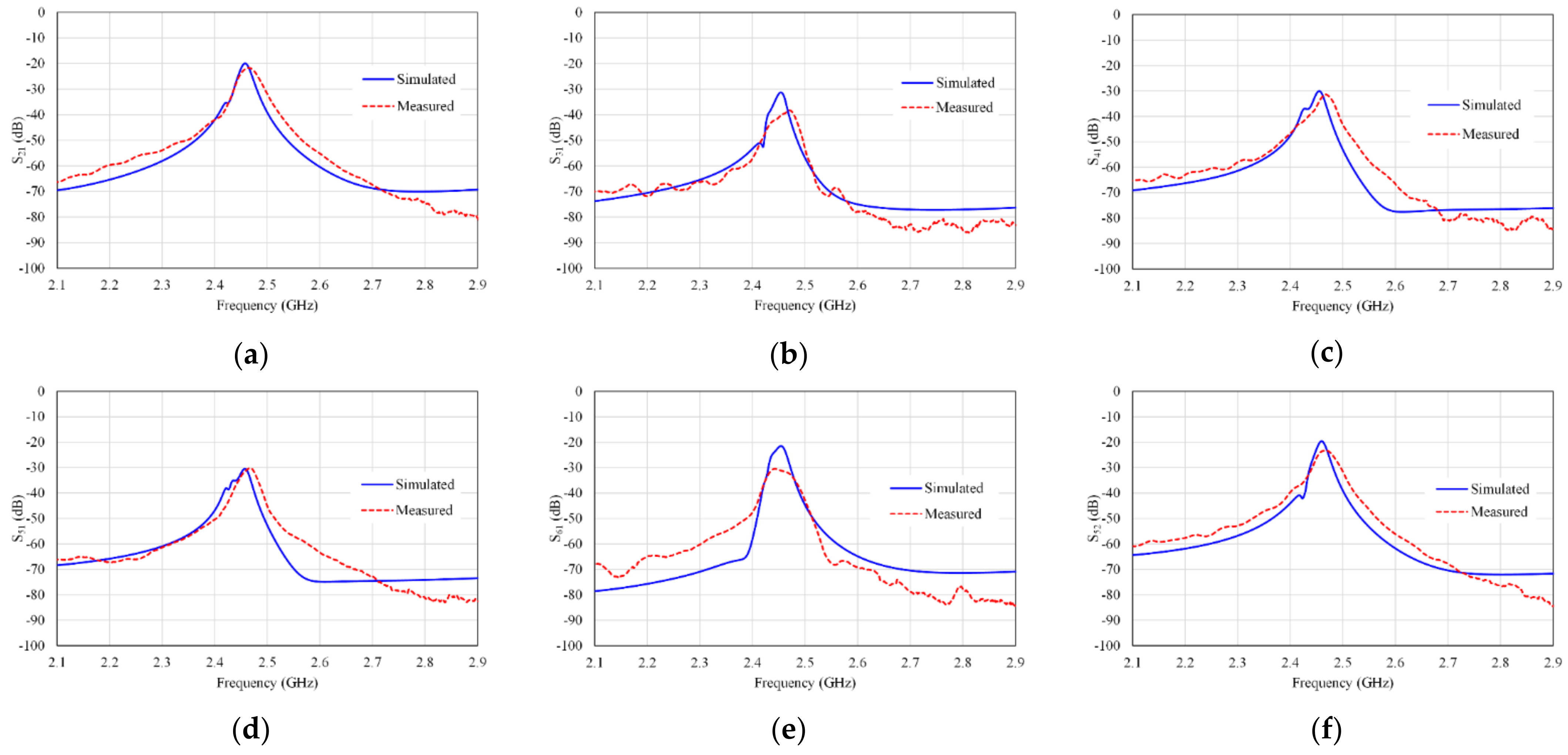
S21 = S32 = S54 = S65,
S31 = S64,
S41 = S63,
S51 = S53 = S62 = S42,
S61 = S43
4. Array Parameters
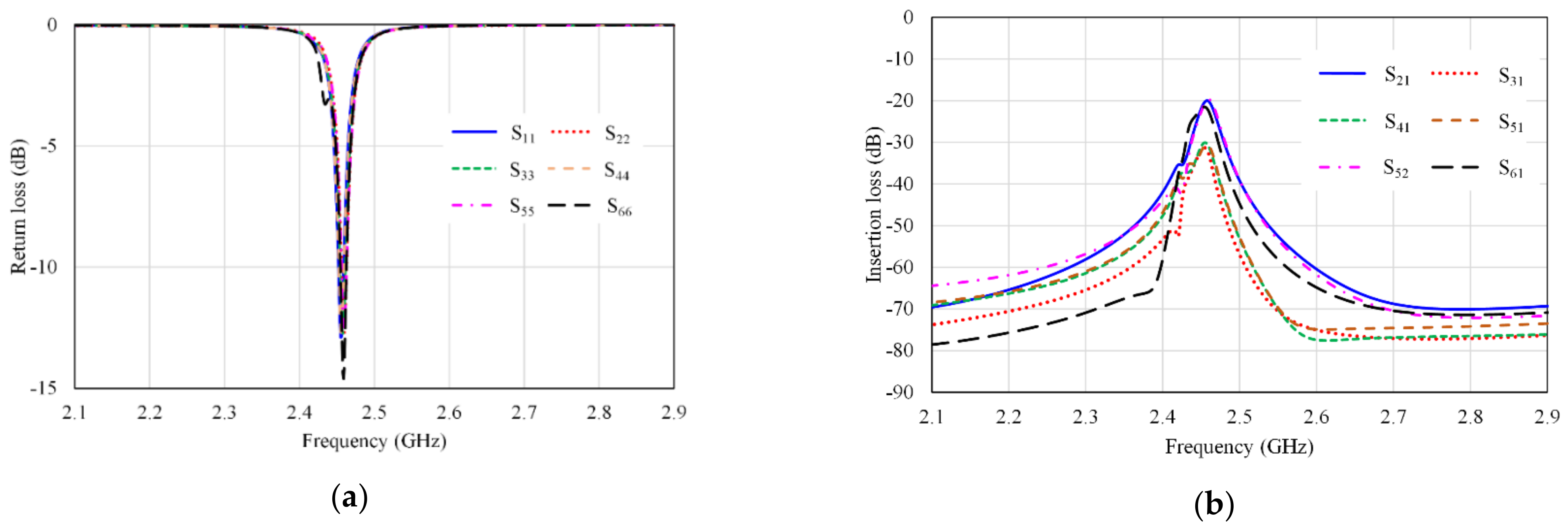
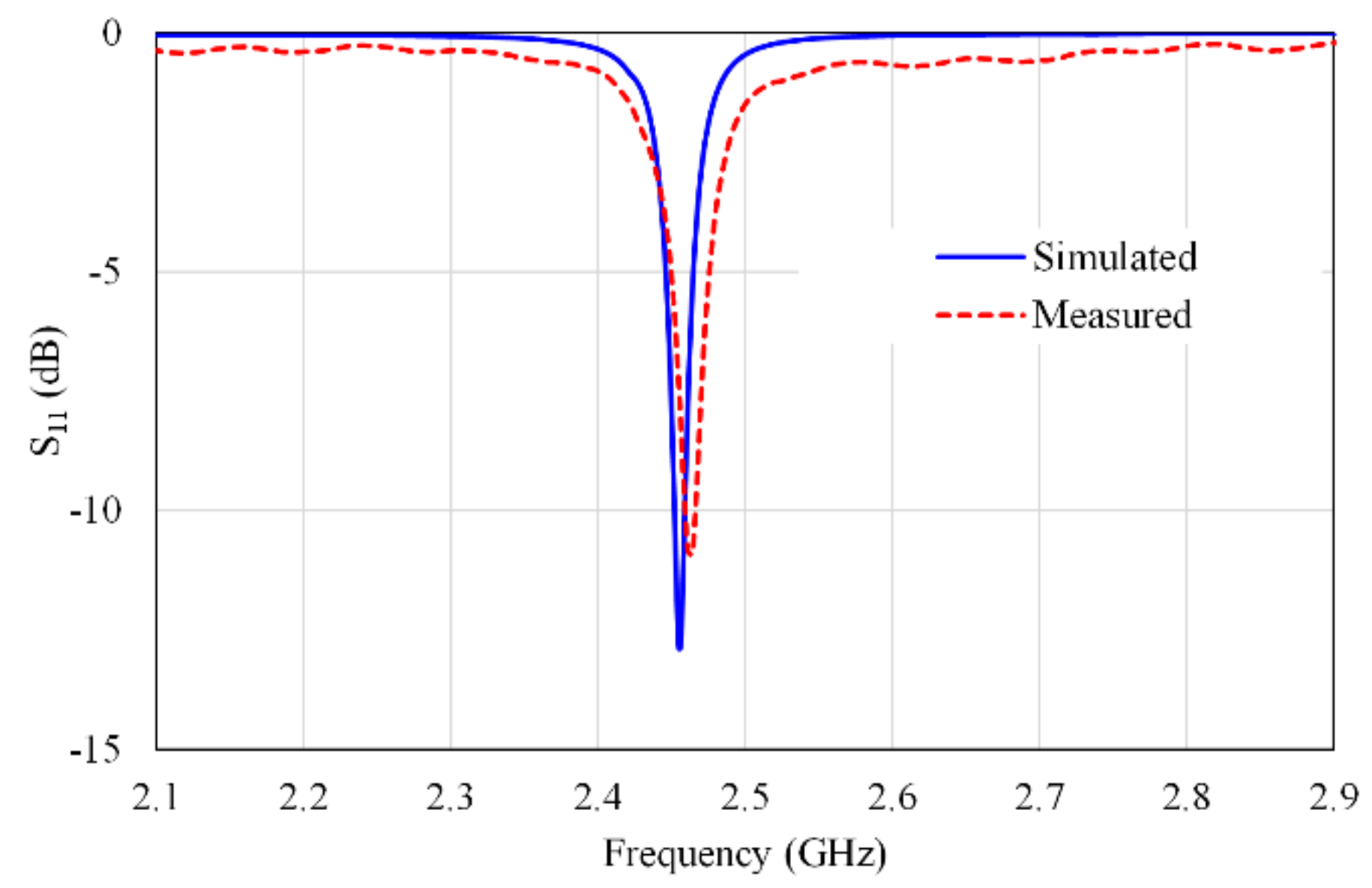
4.1. S-Parameters
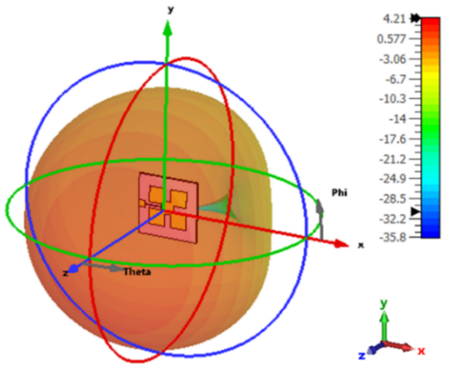
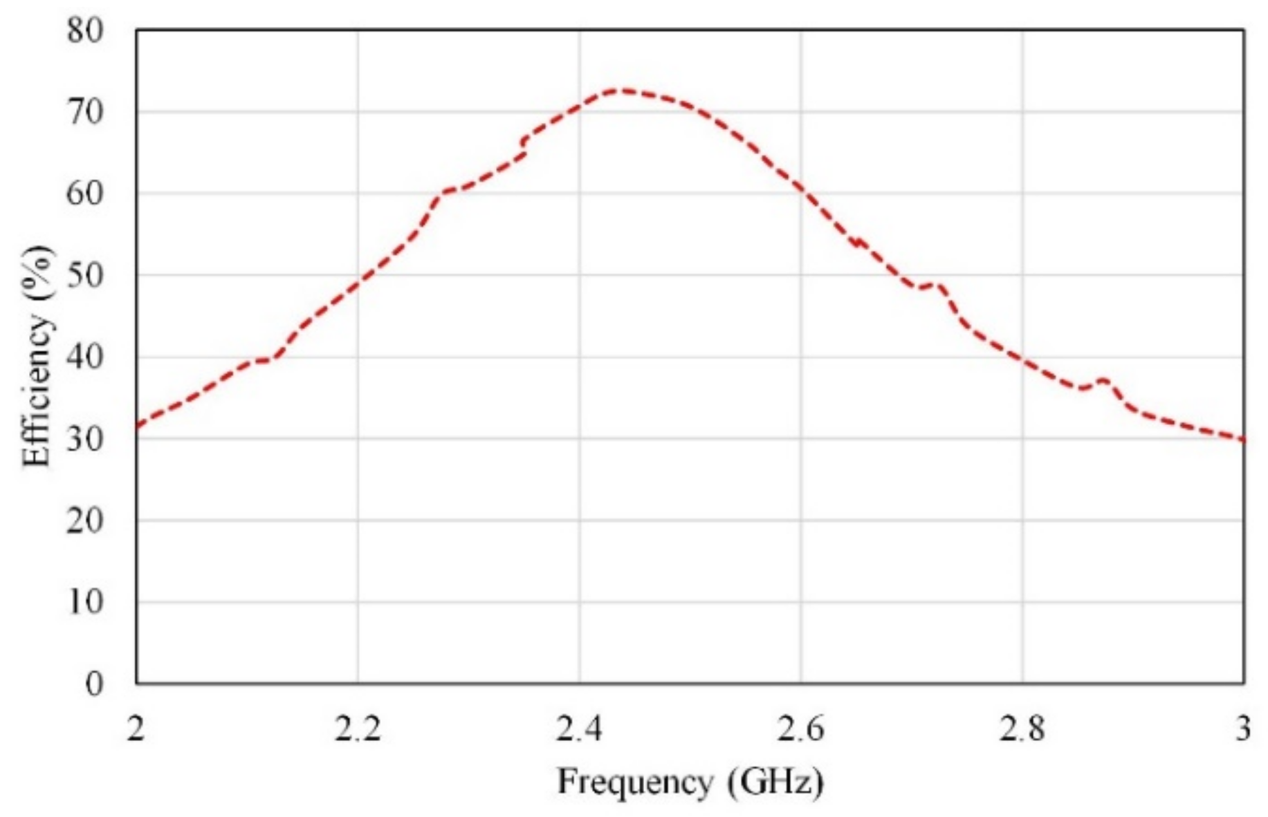
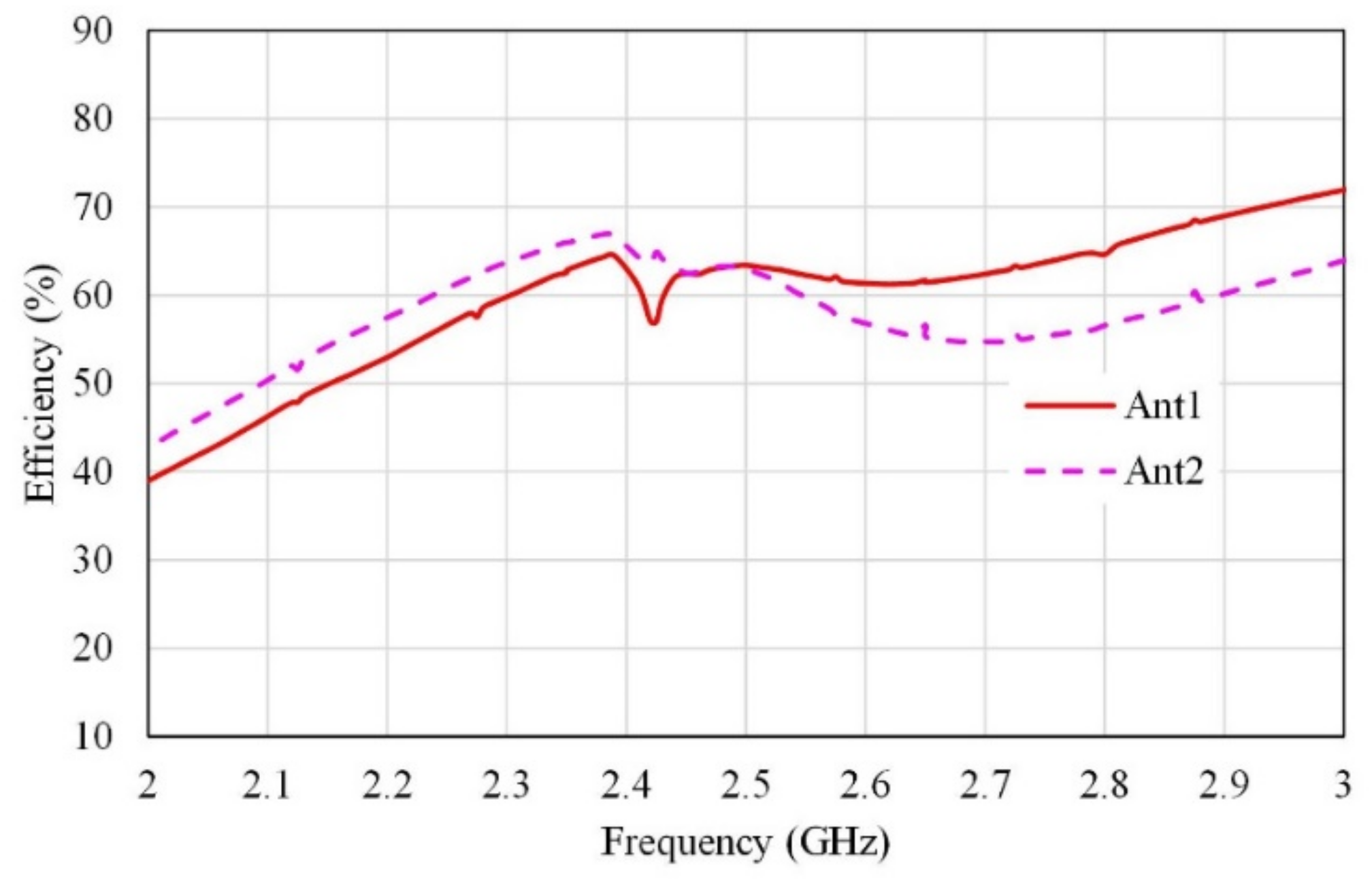
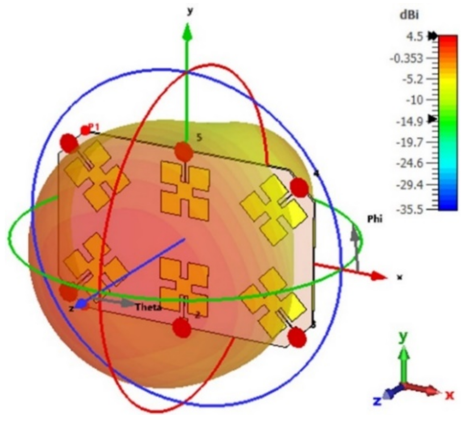
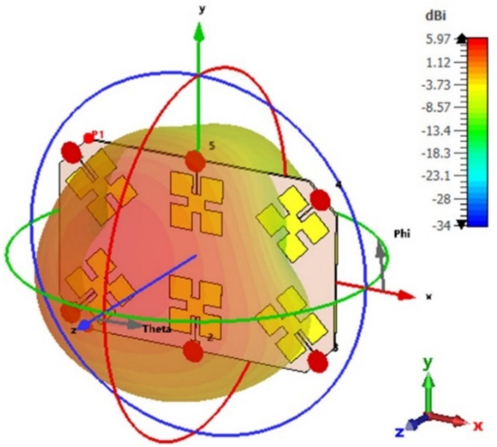
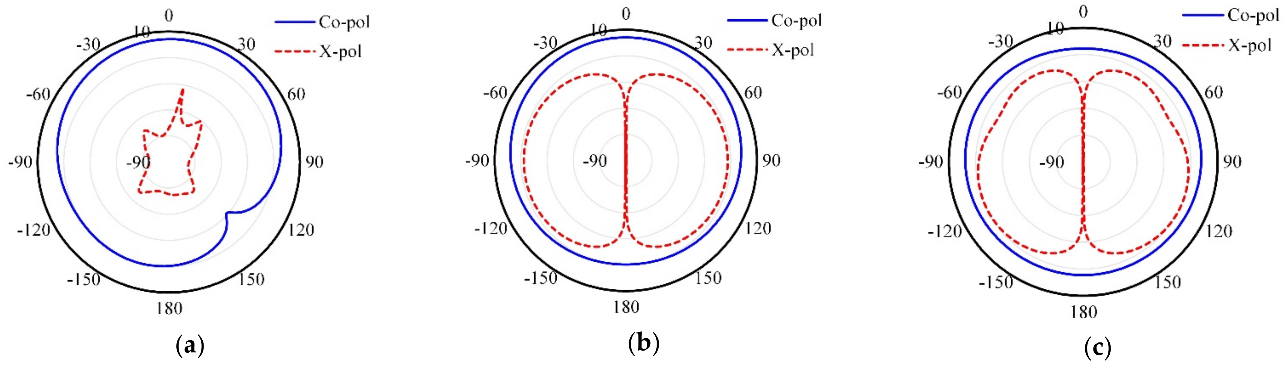
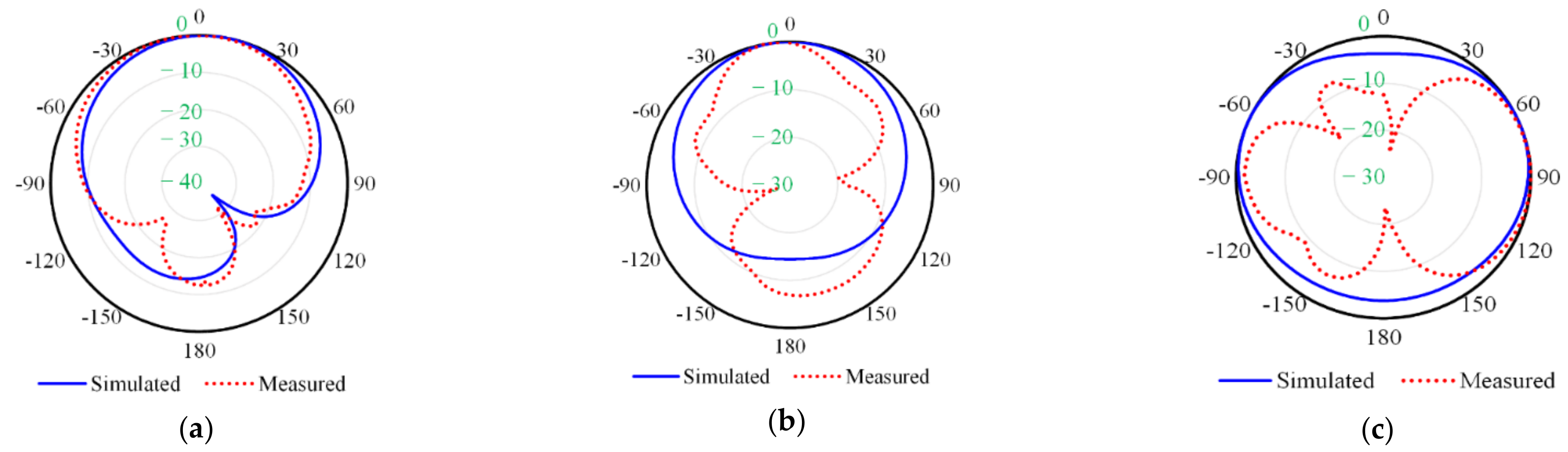
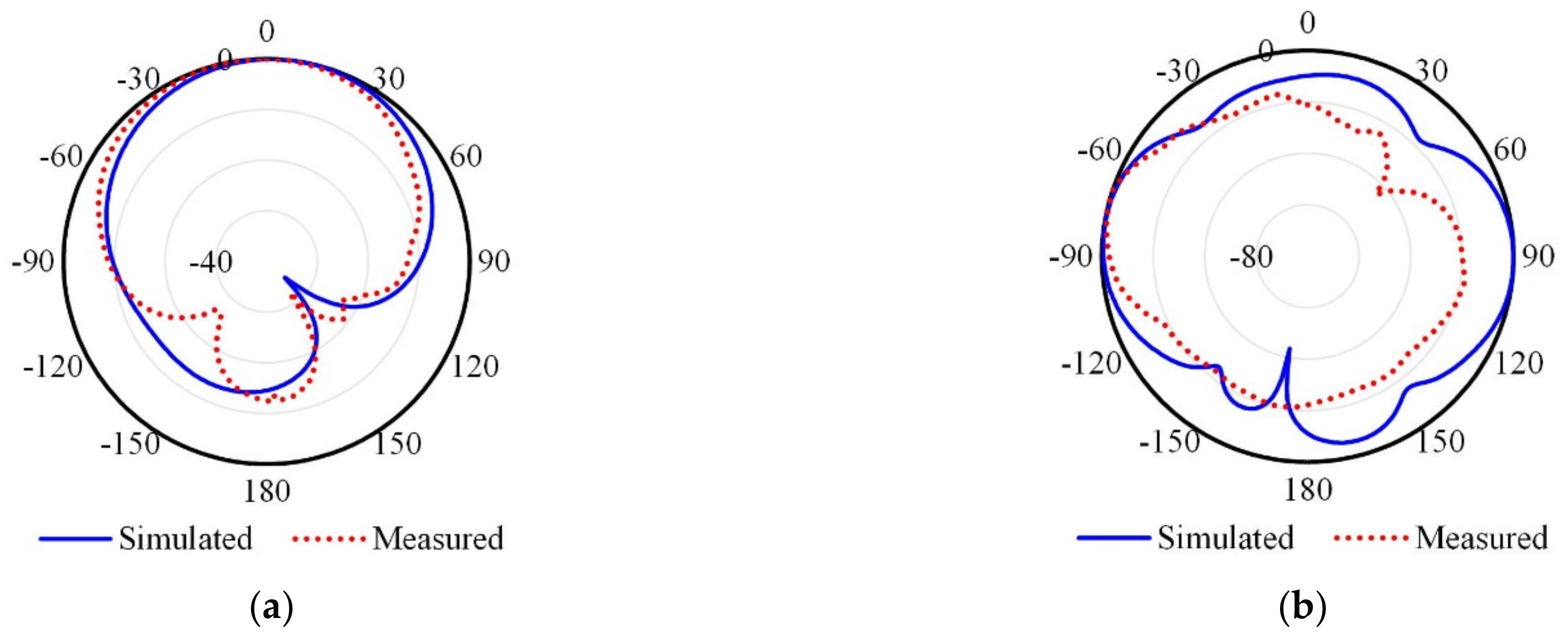
4.2. Radiation Performances
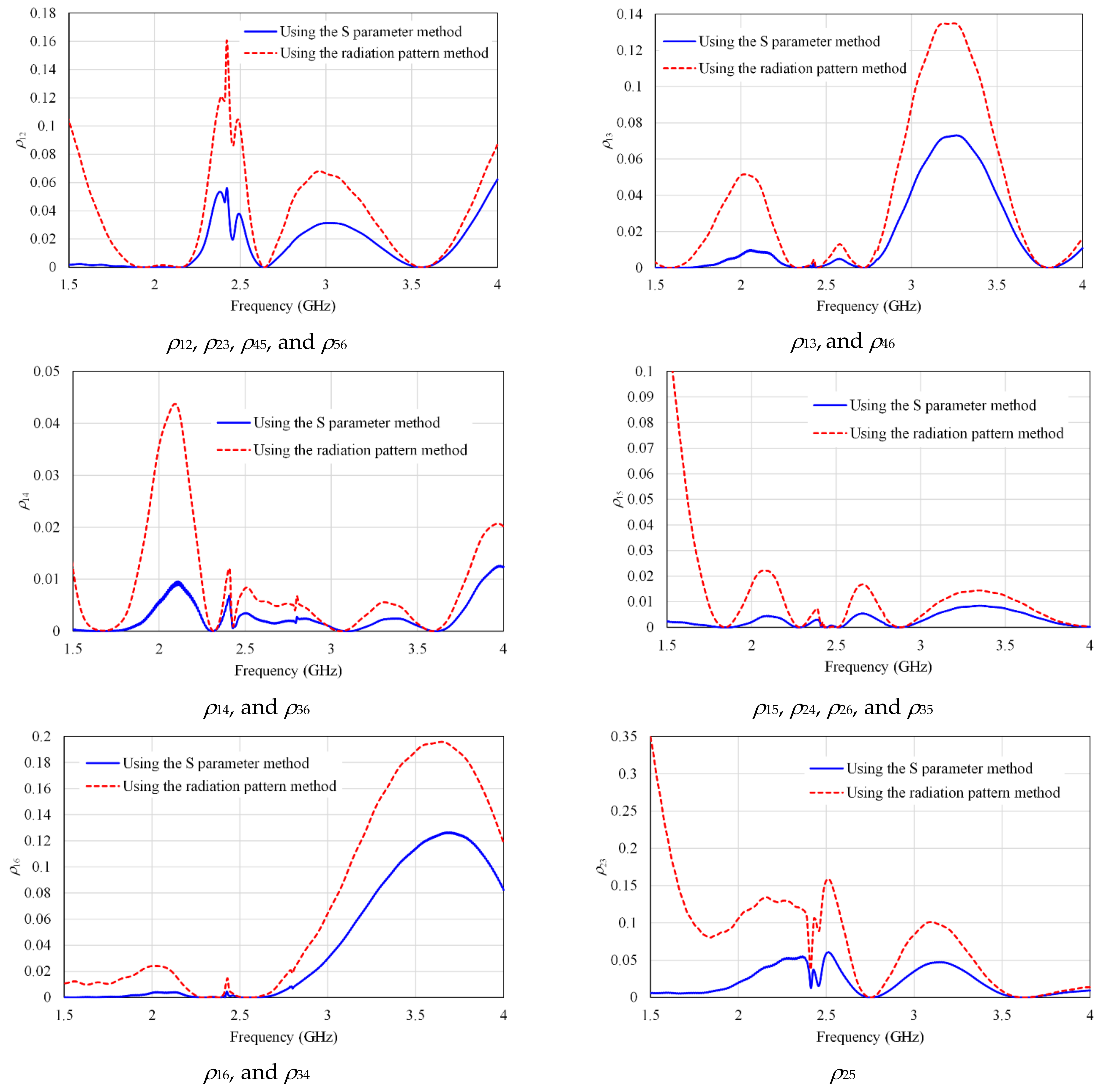
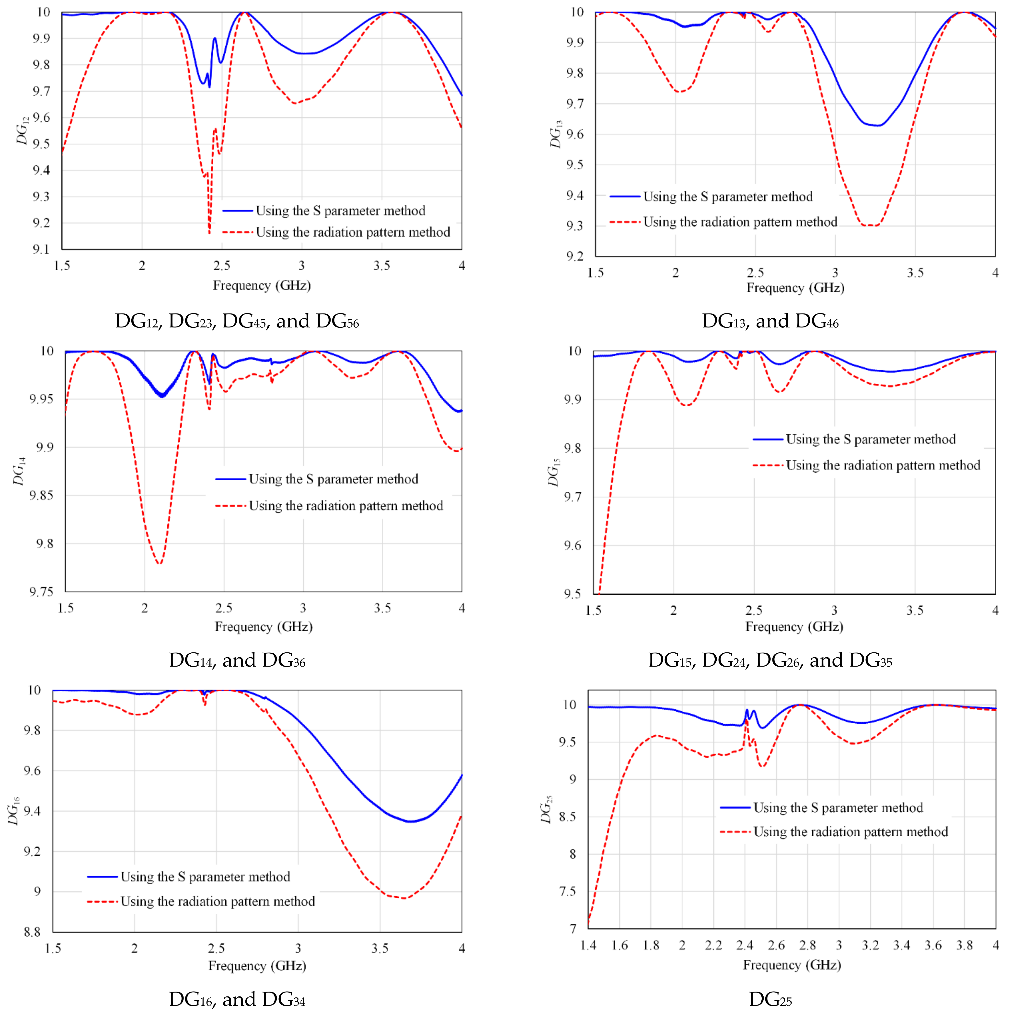
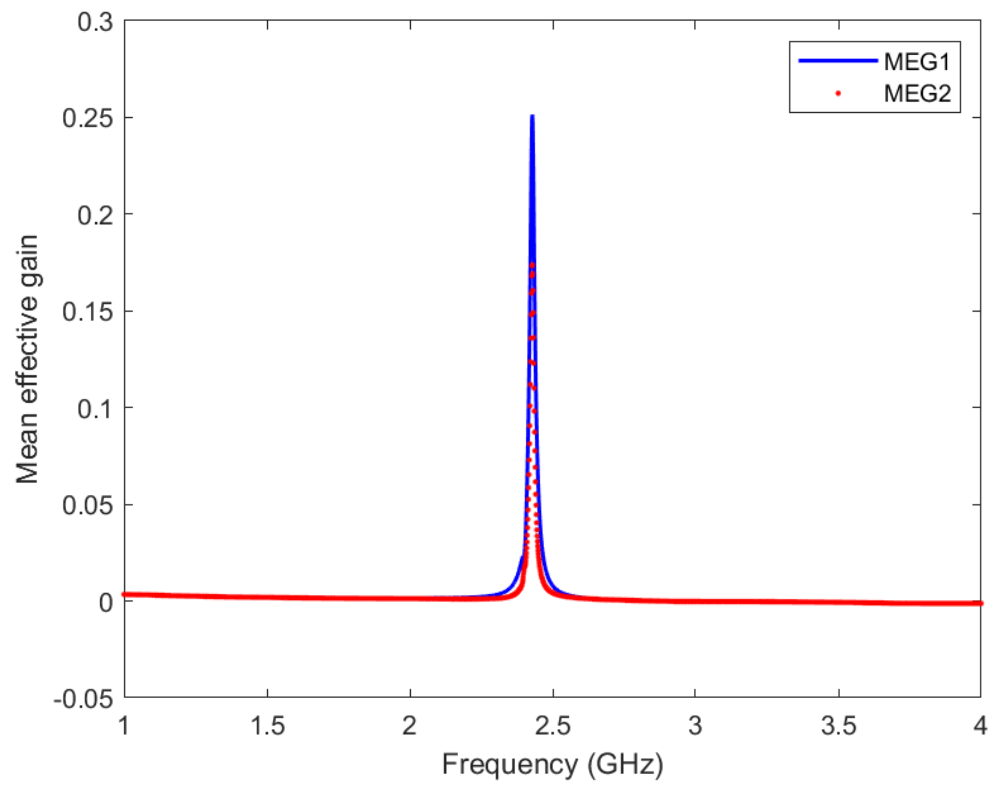
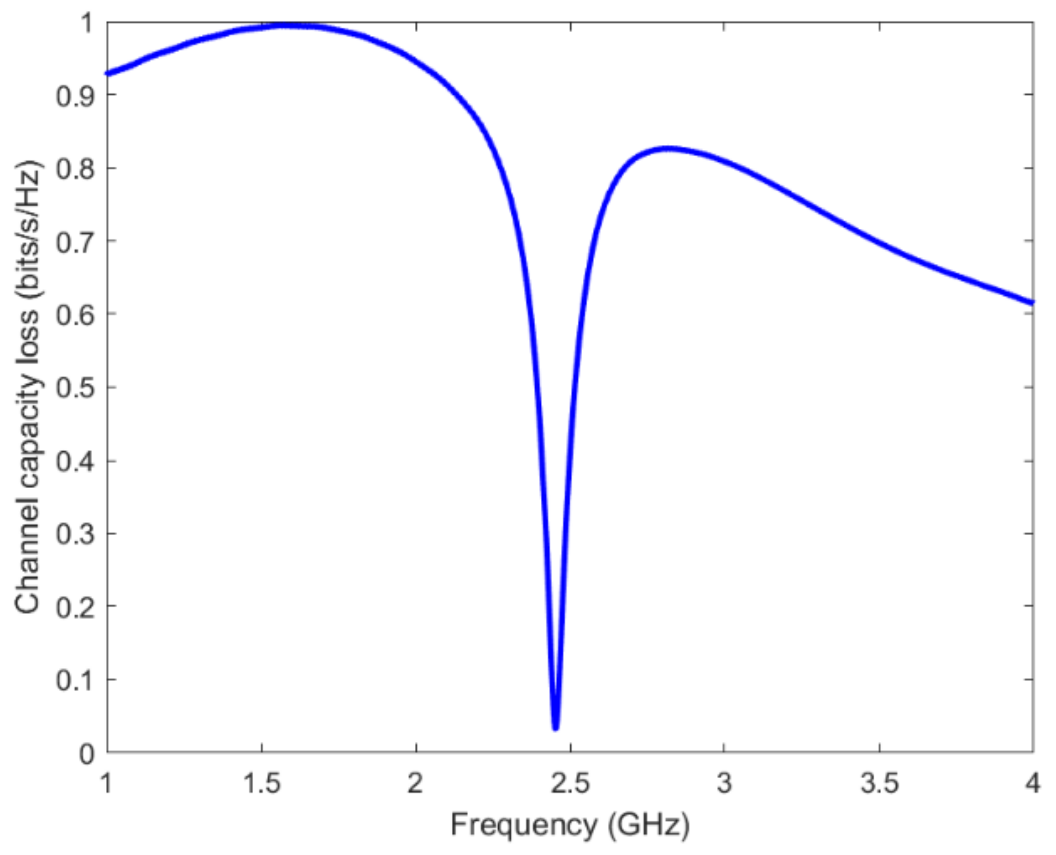
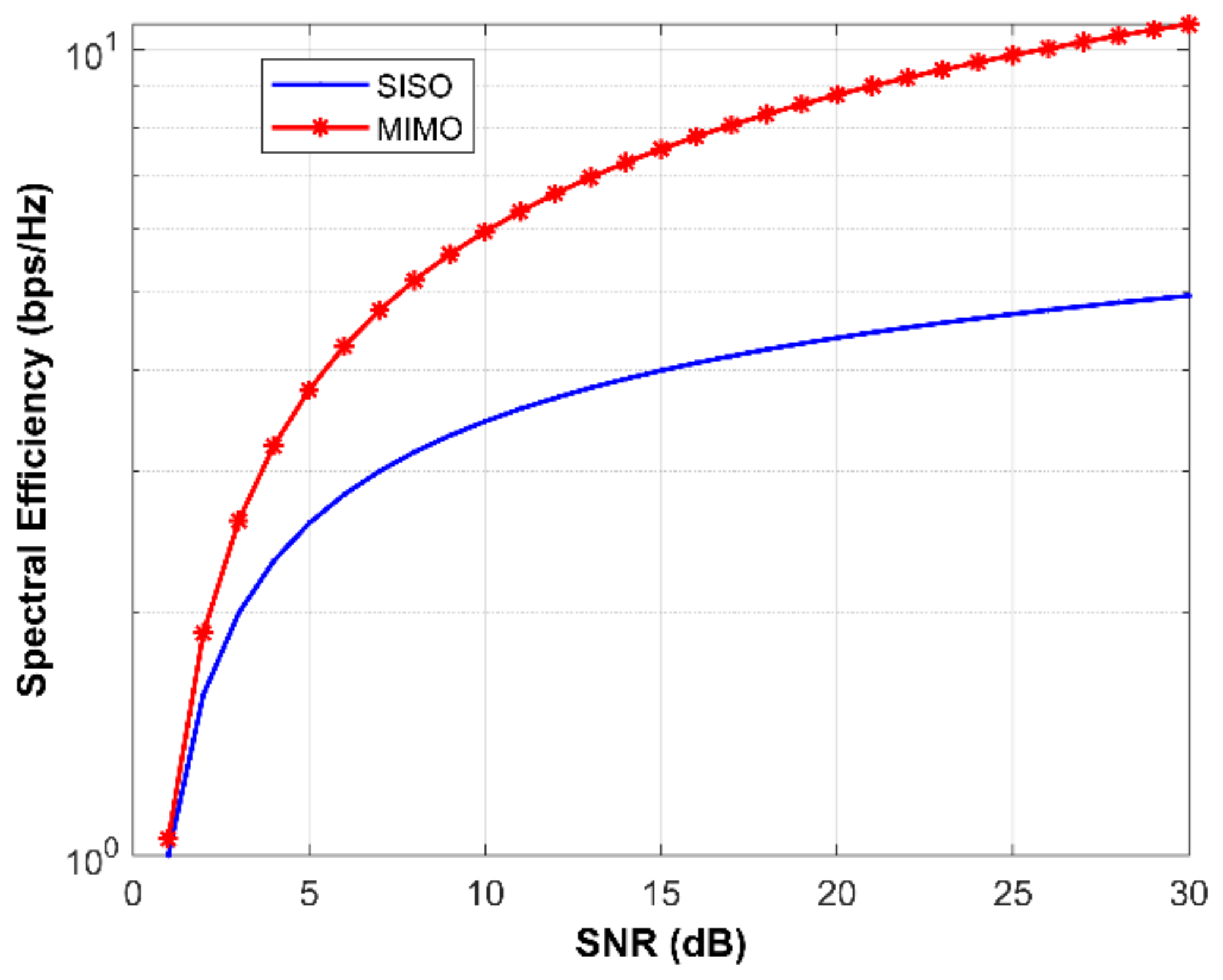
5. MIMO Performance Parameters
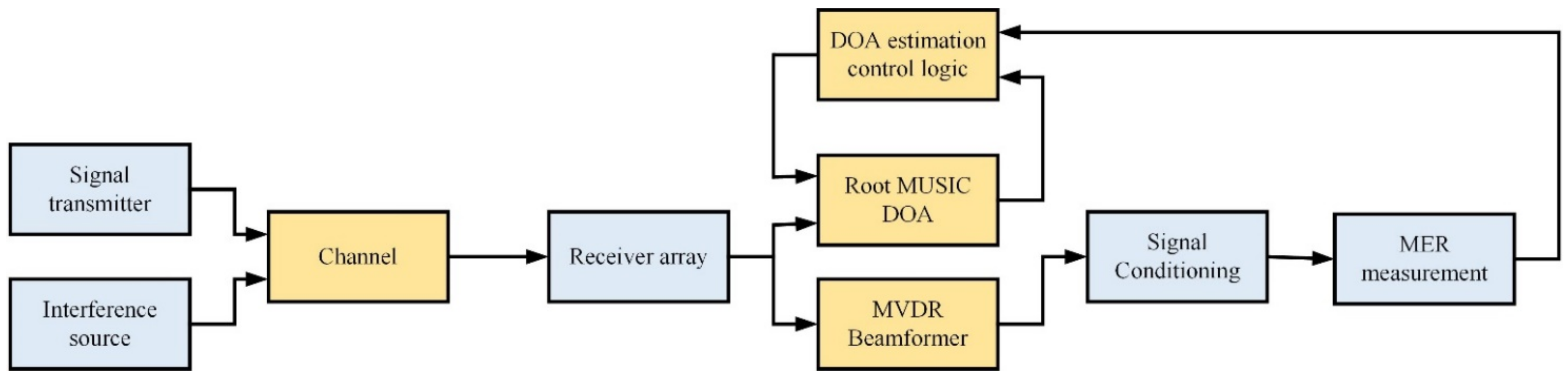
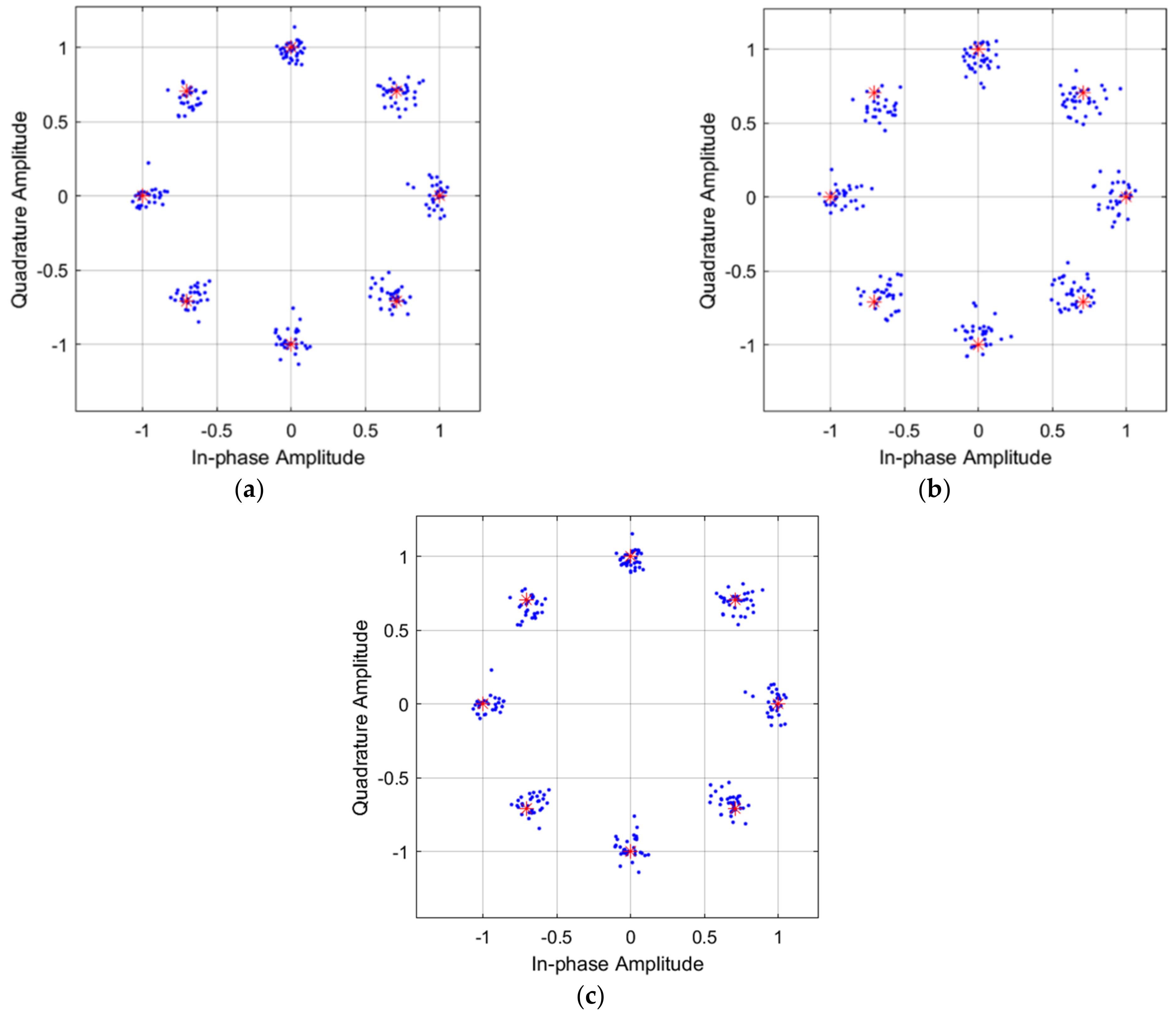
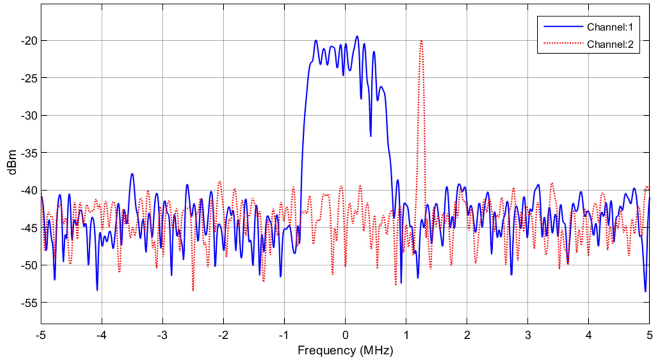
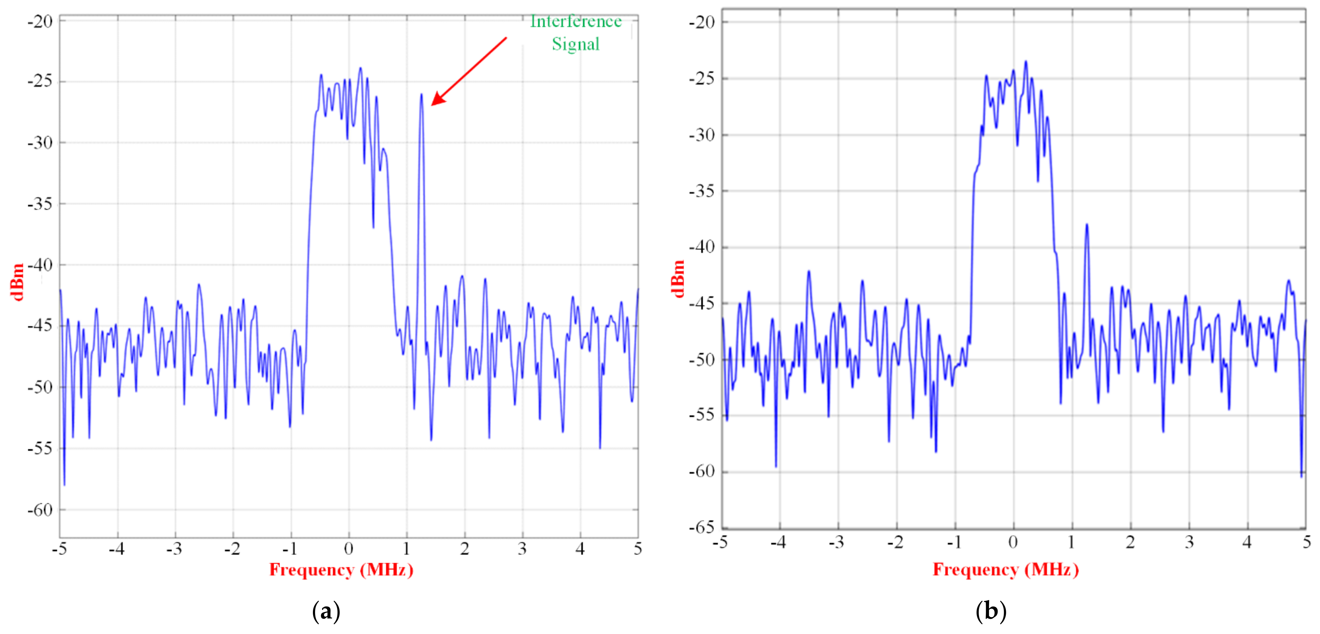
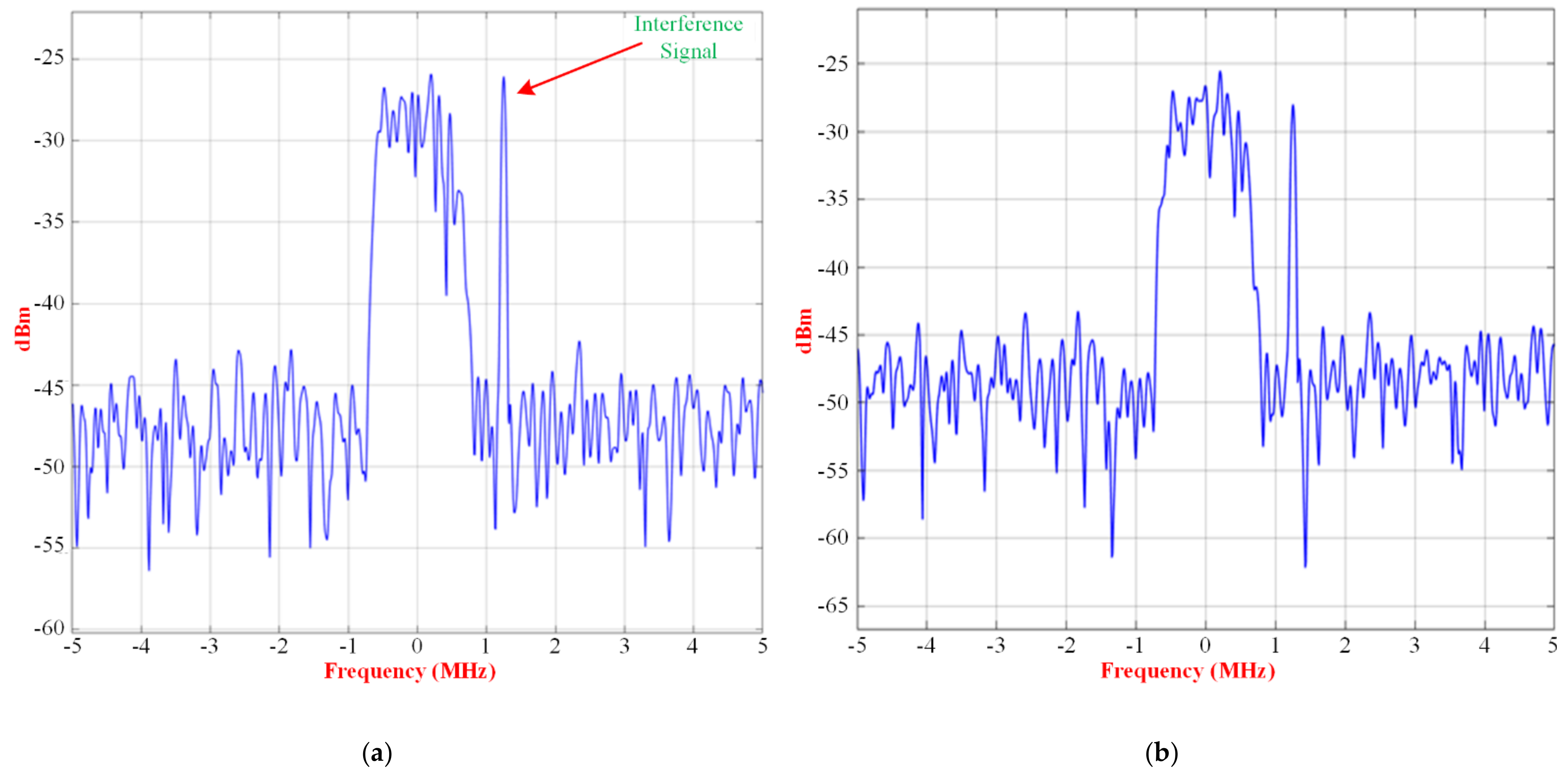
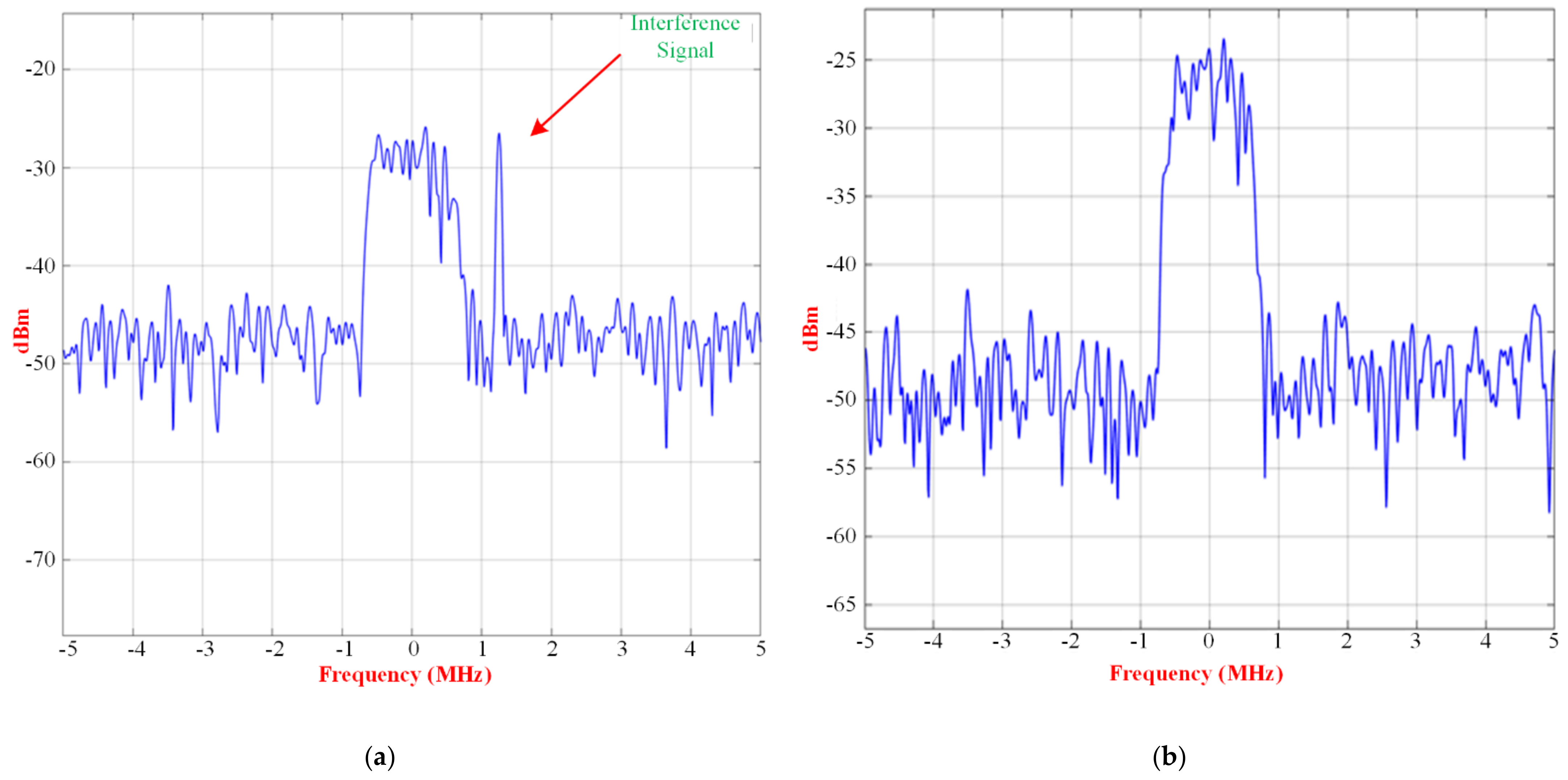
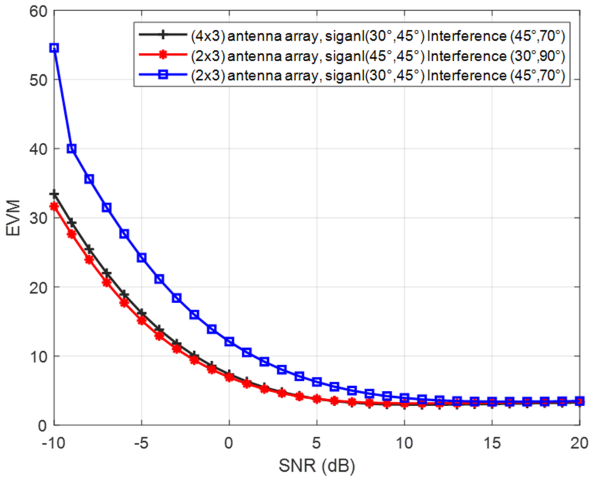
6. Beamforming Function
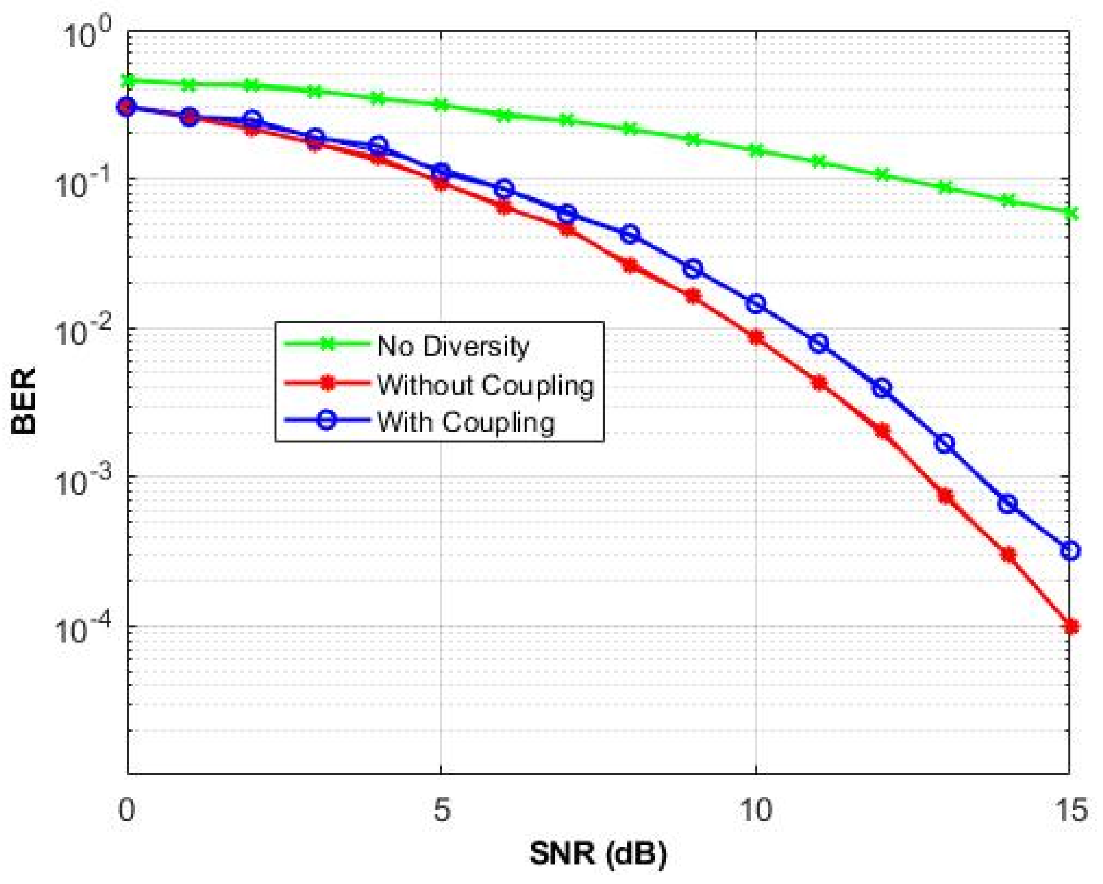
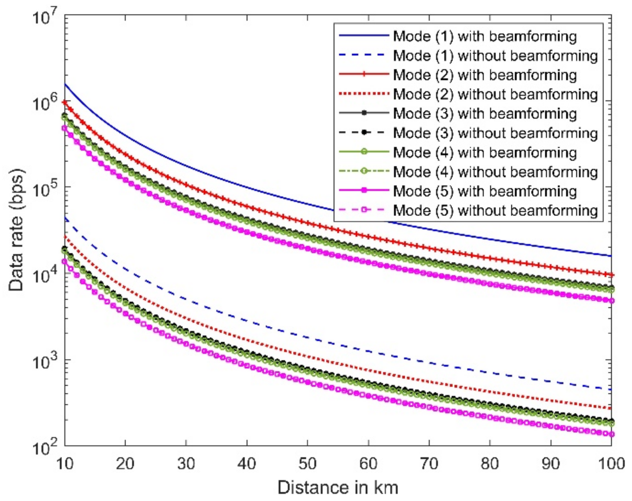
7. Performance in Regional Area Network
8. Conclusions
Author Contributions
Funding
Institutional Review Board Statement
Informed Consent Statement
Data Availability Statement
Conflicts of Interest
References
- Kumar, P.; Urooj, S.; Malibari, A. Design and implementation of quad-element super-wideband MIMO antenna for IoT applications. IEEE Access 2020, 8, 226697–226704. [Google Scholar] [CrossRef]
- Romputtal, A.; Phongcharoenpanich, C. IoT-linked integrated NFC and dual band UHF/2.45 GHz RFID reader antenna scheme. IEEE Access 2019, 7, 177832–177843. [Google Scholar] [CrossRef]
- Kirtania, S.G.; Younes, B.A.; Hossain, A.R.; Karacolak, T.; Sekhar, P.K. CPW-fed flexible ultra-wideband antenna for IoT applications. Micromachines 2021, 12, 453. [Google Scholar] [CrossRef]
- Al-Gburi, A.J.A.; Zakaria, Z.; Palandoken, M.; Ibrahim, I.M.; Althuwayb, A.; Ahmad, S.; Al-Bawri, S.S. Super Compact UWB Monopole Antenna for Small IoT Devices. Comput. Mater. Contin. 2022, 73, 2785–2799. [Google Scholar]
- Sabban, A. Wearable Circular Polarized Antennas for Health Care, 5G, Energy Harvesting, and IoT Systems. Electronics 2022, 11, 427. [Google Scholar] [CrossRef]
- Abdulkawi, W.M.; Nizam-Uddin, N.; Sheta, A.F.A.; Elshafiey, I.; Al-Shaalan, A.M. Towards an Efficient Chipless RFID System for Modern Applications in IoT Networks. Appl. Sci. 2021, 11, 8948. [Google Scholar] [CrossRef]
- Thiruvenkadam, S.; Parthasarathy, E.; Palaniswamy, S.K.; Kumar, S.; Wang, L. Design and Performance Analysis of a Compact Planar MIMO Antenna for IoT Applications. Sensors 2021, 21, 7909. [Google Scholar] [CrossRef]
- Ikram, M. 5G/B5G Internet of Things MIMO Antenna Design. Signals 2022, 3, 3. [Google Scholar] [CrossRef]
- Abdulkawi, W.M.; Malik, W.A.; Rehman, S.U.; Aziz, A.; Sheta, A.F.A.; Alkanhal, M.A. Design of a Compact Dual-Band MIMO Antenna System with High-Diversity Gain Performance in Both Frequency Bands. Micromachines 2021, 12, 383. [Google Scholar] [CrossRef]
- Al Abbas, E.; Ikram, M.; Mobashsher, A.T.; Abbosh, A. MIMO antenna system for multi-band millimeter-wave 5G and wideband 4G mobile communications. IEEE Access 2019, 7, 181916–181923. [Google Scholar] [CrossRef]
- Abdullah, M.; Altaf, A.; Anjum, M.R.; Arain, Z.A.; Jamali, A.A.; Alibakhshikenari, M.; Falcone, F.; Limiti, E. Future smartphone: MIMO antenna system for 5G mobile terminals. IEEE Access 2021, 9, 91593–91603. [Google Scholar] [CrossRef]
- Getu, B.N.; Andersen, J.B. The MIMO cube-a compact MIMO antenna. IEEE Trans. Wirel. Commun. 2005, 4, 1136–1141. [Google Scholar] [CrossRef]
- Kiani, S.H.; Altaf, A.; Abdullah, M.; Muhammad, F.; Shoaib, N.; Anjum, M.R.; Damaševičius, R.; Blažauskas, T. Eight element side edged framed MIMO antenna array for future 5G smart phones. Micromachines 2020, 11, 956. [Google Scholar] [CrossRef] [PubMed]
- Sarkar, D.; Saurav, K.; Srivastava, K.V. Dual band complementary split-ring resonator-loaded printed dipole antenna arrays for pattern diversity multiple-input–multiple-output applications. IET Microw. Antennas Propag. 2016, 10, 1113–1123. [Google Scholar] [CrossRef]
- Li, Q.; Cheung, S.; Wu, D.; Yuk, T. Optically transparent dual-band MIMO antenna using micro-metal mesh conductive film for WLAN system. IEEE Antennas Wirel. Propag. Lett. 2016, 16, 920–923. [Google Scholar] [CrossRef]
- Kabiri, Y.; Borja, A.L.; Kelly, J.R.; Xiao, P. A technique for MIMO antenna design with flexible element number and pattern diversity. IEEE Access 2019, 7, 86157–86167. [Google Scholar] [CrossRef]
- Desai, A.; Bui, C.D.; Patel, J.; Upadhyaya, T.; Byun, G.; Nguyen, T.K. Compact wideband four element optically transparent MIMO antenna for mm-wave 5G applications. IEEE Access 2020, 8, 194206–194217. [Google Scholar] [CrossRef]
- Jiang, W.; Liu, B.; Cui, Y.; Hu, W. High-isolation eight-element MIMO array for 5G smartphone applications. IEEE Access 2019, 7, 34104–34112. [Google Scholar] [CrossRef]
- Chen, X.; Zhang, S.; Li, Q. A review of mutual coupling in MIMO systems. IEEE Access 2018, 6, 24706–24719. [Google Scholar] [CrossRef]
- Boukarkar, A.; Lin, X.Q.; Jiang, Y.; Nie, L.Y.; Mei, P.; Yu, Y.Q. A miniaturized extremely close-spaced four-element dual-band MIMO antenna system with polarization and pattern diversity. IEEE Antennas Wirel. Propag. Lett. 2017, 17, 134–137. [Google Scholar] [CrossRef]
- Sun, L.; Feng, H.; Li, Y.; Zhang, Z. Compact 5G MIMO mobile phone antennas with tightly arranged orthogonal-mode pairs. IEEE Trans. Antennas Propag. 2018, 66, 6364–6369. [Google Scholar] [CrossRef]
- Li, J.; Zhang, X.; Wang, Z.; Chen, X.; Chen, J.; Li, Y.; Zhang, A. Dual-band eight-antenna array design for MIMO applications in 5G mobile terminals. IEEE Access 2019, 7, 71636–71644. [Google Scholar] [CrossRef]
- Tiwari, R.; Singh, P.; Kanaujia, B.; Srivastava, K. Neutralization Technique Based Two and Four Port High Isolation MIMO Antennas for UWB Communication. AEU—Int. J. Electron. Commun. 2019, 110, 152828. [Google Scholar] [CrossRef]
- Shen, X.; Liu, F.; Zhao, L.; Huang, G.-L.; Shi, X.; Huang, Q.; Chen, A. Decoupling of Two Strongly Coupled Dual-Band Antennas With Reactively Loaded Dummy Element Array. IEEE Access 2019, 7, 154672–154682. [Google Scholar] [CrossRef]
- Ren, Z.; Zhao, A. Dual-Band MIMO Antenna with Compact Self-Decoupled Antenna Pairs for 5G Mobile Applications. IEEE Access 2019, 7, 82288–82296. [Google Scholar] [CrossRef]
- Hu, W.; Qian, L.; Gao, S.; Wen, L.-H.; Luo, Q.; Xu, H.; Liu, X.-K.; Liu, Y.; Wang, W. Dual-Band Eight-Element MIMO Array Using Multi-Slot Decoupling Technique for 5G Terminals. IEEE Access 2019, 7, 153910–153920. [Google Scholar] [CrossRef]
- Abdullah, M.; Kiani, S.; Iqbal, A. Eight Element Multiple-Input Multiple-Output (MIMO) Antenna for 5G Mobile Applications. IEEE Access 2019, 7, 134488–134495. [Google Scholar] [CrossRef]
- Li, T.; Geyi, W. Design of MIMO beamforming antenna array for mobile handsets. Prog. Electromagn. Res. C 2019, 94, 13–28. [Google Scholar] [CrossRef]
- Rao, L.; Malviya, L.; Chawla, M.; Parmar, A. MIMO-Array Antenna With Beamforming for 5G Applications. In Proceedings of the 2021 10th IEEE International Conference on Communication Systems and Network Technologies (CSNT), Bhopal, India, 18–19 June 2021; pp. 27–32. [Google Scholar]
- Abdulkawi, W.M.; Sheta, A.F.A.; Elshafiey, I.; Alkanhal, M.A. Design of Low-Profile Single-and Dual-Band Antennas for IoT Applications. Electronics 2021, 10, 2766. [Google Scholar] [CrossRef]
- Gangwar, R.K.; Singh, S.P.; Kumar, D. A modified fractal rectangular curve dielectric resonator antenna for WiMAX application. Prog. Electromagn. Res. 2010, 12, 37–51. [Google Scholar] [CrossRef]
- Dhar, S.; Ghatak, R.; Gupta, B.; Poddar, D.R. A wideband Minkowski fractal dielectric resonator antenna. IEEE Trans. Antennas Propag. 2013, 61, 2895–2903. [Google Scholar] [CrossRef]
- Muhsin, M.Y.; Salim, A.J.; Ali, J.K. Compact MIMO Antenna Designs Based on Hybrid Fractal Geometry for 5G Smartphone Applications. Prog. Electromagn. Res. C 2022, 118, 247–262. [Google Scholar] [CrossRef]
- Sharma, N.; Singh, H.S.; Khanna, R. Design and Analysis of Multiband Fractal Antenna for MIMO/Diversity Applications. Wirel. Pers. Commun. 2022, 122, 3671–3686. [Google Scholar] [CrossRef]
- Sheta, A.; Al-Eshaikh, M. A new small size non-degenerate dual-mode patch filter. J. Electromagn. Waves Appl. 2011, 25, 1504–1514. [Google Scholar] [CrossRef]
- Mahmoud, S.F.; Sheta, A.; Alkanhal, M.A.; Alhekail, Z. Analysis and design of compact wide tunable-band antenna based on reactively loaded patch. Microw. Opt. Technol. Lett. 2012, 54, 884–888. [Google Scholar] [CrossRef]
- Sheta, A.; Dib, N.; Mohra, A. Investigation of new nondegenerate dual-mode microstrip patch filter. IEE Proc. -Microw. Antennas Propag. 2006, 153, 89–95. [Google Scholar] [CrossRef]
- Mansour, R.R. Design of superconductive multiplexers using single-mode and dual-mode filters. IEEE Trans. Microw. Theory Tech. 1994, 42, 1411–1418. [Google Scholar] [CrossRef]
- Du, Z.; Gong, K.; Fu, J.; Gao, B. Analysis of microstrip fractal patch antenna for multi-band communication [by FDTD]. Electron. Lett. 2001, 37, 805–806. [Google Scholar] [CrossRef]
- Zhao, L.; Liu, F.; Shen, X.; Jing, G.; Cai, Y.-M.; Li, Y. A high-pass antenna interference cancellation chip for mutual coupling reduction of antennas in contiguous frequency bands. IEEE Access 2018, 6, 38097–38105. [Google Scholar] [CrossRef]
- Yu, K.; Li, Y.; Liu, X. Mutual coupling reduction of a MIMO antenna array using 3-D novel meta-material structures. Appl. Comput. Electromagn. Soc. J. 2018, 6, 758–763. [Google Scholar]
- Jiang, T.; Jiao, T.; Li, Y. A low mutual coupling MIMO antenna using periodic multi-layered electromagnetic band gap structures. Appl. Comput. Electromagn. Soc. J. 2018, 33, 305–311. [Google Scholar]
- Geozandas. Time-Domain Antenna Measurement Systems. Available online: https://geozondas.com/main_page.php?pusl=12 (accessed on 26 July 2022).
- Shayea, I.; Rahman, T.A.; Azmi, M.H.; Islam, M.R. Real measurement study for rain rate and rain attenuation conducted over 26 GHz microwave 5G link system in Malaysia. IEEE Access 2018, 6, 19044–19064. [Google Scholar] [CrossRef]
- Khalid, M.; Iffat Naqvi, S.; Hussain, N.; Rahman, M.; Mirjavadi, S.S.; Khan, M.J.; Amin, Y. 4-Port MIMO antenna with defected ground structure for 5G millimeter wave applications. Electronics 2020, 9, 71. [Google Scholar] [CrossRef] [Green Version]
- Votis, C.; Tatsis, G.; Kostarakis, P. Envelope correlation parameter measurements in a MIMO antenna array configuration. Int. J. Commun. Netw. Syst. Sci. 2010, 3, 350. [Google Scholar] [CrossRef]
- Liu, F.; Guo, J.; Zhao, L.; Huang, G.-L.; Li, Y.; Yin, Y. Ceramic superstrate-based decoupling method for two closely packed antennas with cross-polarization suppression. IEEE Trans. Antennas Propag. 2020, 69, 1751–1756. [Google Scholar] [CrossRef]
- Roy, S.; Chakraborty, U. Mutual coupling reduction in a multi-band MIMO antenna using meta-inspired decoupling network. Wirel. Pers. Commun. 2020, 114, 3231–3246. [Google Scholar] [CrossRef]
- Saxena, G.; Jain, P.; Awasthi, Y.K. High diversity gain MIMO-antenna for UWB application with WLAN notch band characteristic including human interface devices. Wirel. Pers. Commun. 2020, 112, 105–121. [Google Scholar] [CrossRef]
- Sharawi, M.S. Printed multi-band MIMO antenna systems and their performance metrics [wireless corner]. IEEE Antennas Propag. Mag. 2013, 55, 218–232. [Google Scholar] [CrossRef]
- Kulkarni, J.; Desai, A.; Sim, C.-Y.D. Wideband Four-Port MIMO antenna array with high isolation for future wireless systems. AEU-Int. J. Electron. Commun. 2021, 128, 153507. [Google Scholar] [CrossRef]
- Tariq, S.; Naqvi, S.I.; Hussain, N.; Amin, Y. A Metasurface-Based MIMO Antenna for 5G Millimeter-Wave Applications. IEEE Access 2021, 9, 51805–51817. [Google Scholar] [CrossRef]
- Abouda, A.A.; El-Sallabi, H.M.; Haggman, S. Effect of mutual coupling on BER performance of Alamouti scheme. In Proceedings of the 2006 IEEE Antennas and Propagation Society International Symposium, Albuquerque, NM, USA, 9–14 July 2006; pp. 4797–4800. [Google Scholar]
- Gupta, I.; Ksienski, A. Effect of mutual coupling on the performance of adaptive arrays. IEEE Trans. Antennas Propag. 1983, 31, 785–791. [Google Scholar] [CrossRef]
- Wu, Y.; Linnartz, J.P.; Bergmans, J.; Attallah, S. Effects of antenna mutual coupling on the performance of MIMO systems. In Proceedings of the 29th Symposium on Information Theory in the Benelux, Rotterdam, The Netherlands, 11–12 May 2010; pp. 1–8. [Google Scholar]
- Van Trees, H.L. Optimum Array Processing: Part IV of Detection, Estimation, and Modulation Theory; John Wiley & Sons: New York, NY, USA, 2004. [Google Scholar]
- Proakis, J.G.; Salehi, M. Digital Communications; McGraw-Hill: New York, NY, USA, 2001; Volume 4. [Google Scholar]
- Mathworks. Available online: https://www.mathworks.com/ (accessed on 31 May 2022).


| Ref. | Bandwidth (GHz) | Isolation Level (dB) | ECC Value | Size (λ0 × λ0) | Number of Radiating Elements |
|---|---|---|---|---|---|
| [13] | 24.1–27.2 | 16 | 0.1 | 2.08 × 1.73 | 2 |
| [14] | 3.4–3.6 | 15 | 0.16 | 1.43 × 0.85 | 4 |
| [16] | 3.4–3.6 | 18.4 | 0.08 | 1.2 × 1.2 | 8 |
| [21] | 3.4–3.6 | 20 | 0.06 | 1.75 × 0.88 | 4 |
| [22] | 3.4–3.6 | 13 | 0.1 | 1.63 × 0.82 | 8 |
| [23] | 3.6–9.8 | 17.3 | 0.04 | 1.06 × 0.75 | 4 |
| [24] | 2–3 | 8 | 0.25 | 0.57 × 0.57 | 2 |
| This Work | 2.43–2.48 | 20 | 0.01 | 1.22 × 0.79 | 6 |
| Case Number | Signal (Azimuthal, Elevation) Angles | Interference (Azimuthal, Elevation) Angles | Array Size | Interference Peak Power without Beamforming in dBm | Interference Peak Power with Beamforming in dBm |
|---|---|---|---|---|---|
| 1 | ) | ) | 3 × 2 | −26 | −38 |
| 2 | ) | ) | 3 × 2 | −26 | −28 |
| 3 | ) | ) | 3 × 4 | −27 | Almost removed |
Publisher’s Note: MDPI stays neutral with regard to jurisdictional claims in published maps and institutional affiliations. |
© 2022 by the authors. Licensee MDPI, Basel, Switzerland. This article is an open access article distributed under the terms and conditions of the Creative Commons Attribution (CC BY) license (https://creativecommons.org/licenses/by/4.0/).
Share and Cite
Abdulkawi, W.M.; Alqaisei, M.A.; Sheta, A.-F.A.; Elshafiey, I. New Compact Antenna Array for MIMO Internet of Things Applications. Micromachines 2022, 13, 1481. https://doi.org/10.3390/mi13091481
Abdulkawi WM, Alqaisei MA, Sheta A-FA, Elshafiey I. New Compact Antenna Array for MIMO Internet of Things Applications. Micromachines. 2022; 13(9):1481. https://doi.org/10.3390/mi13091481
Chicago/Turabian StyleAbdulkawi, Wazie M., Mohammed A. Alqaisei, Abdel-Fattah A. Sheta, and Ibrahim Elshafiey. 2022. "New Compact Antenna Array for MIMO Internet of Things Applications" Micromachines 13, no. 9: 1481. https://doi.org/10.3390/mi13091481