
Laser Additive Manufacturing of Anti-Tetrachiral Endovascular Stents with Negative Poisson’s Ratio and Favorable Cytocompatibility

Abstract
:1. Introduction
2. Materials and Methods
2.1. Simulation
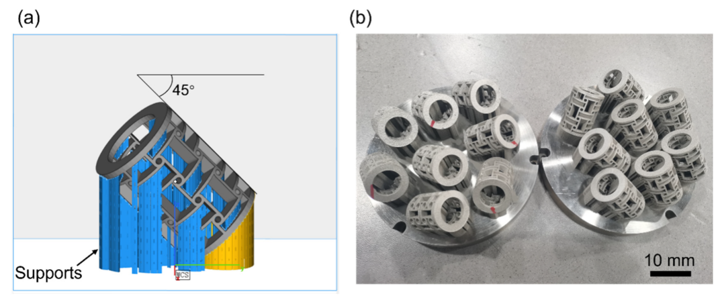
2.2. LPBF Process
2.3. Experimentation
2.4. Biocompatibility Test
3. Results and Discussion
4. Conclusions
- (1)
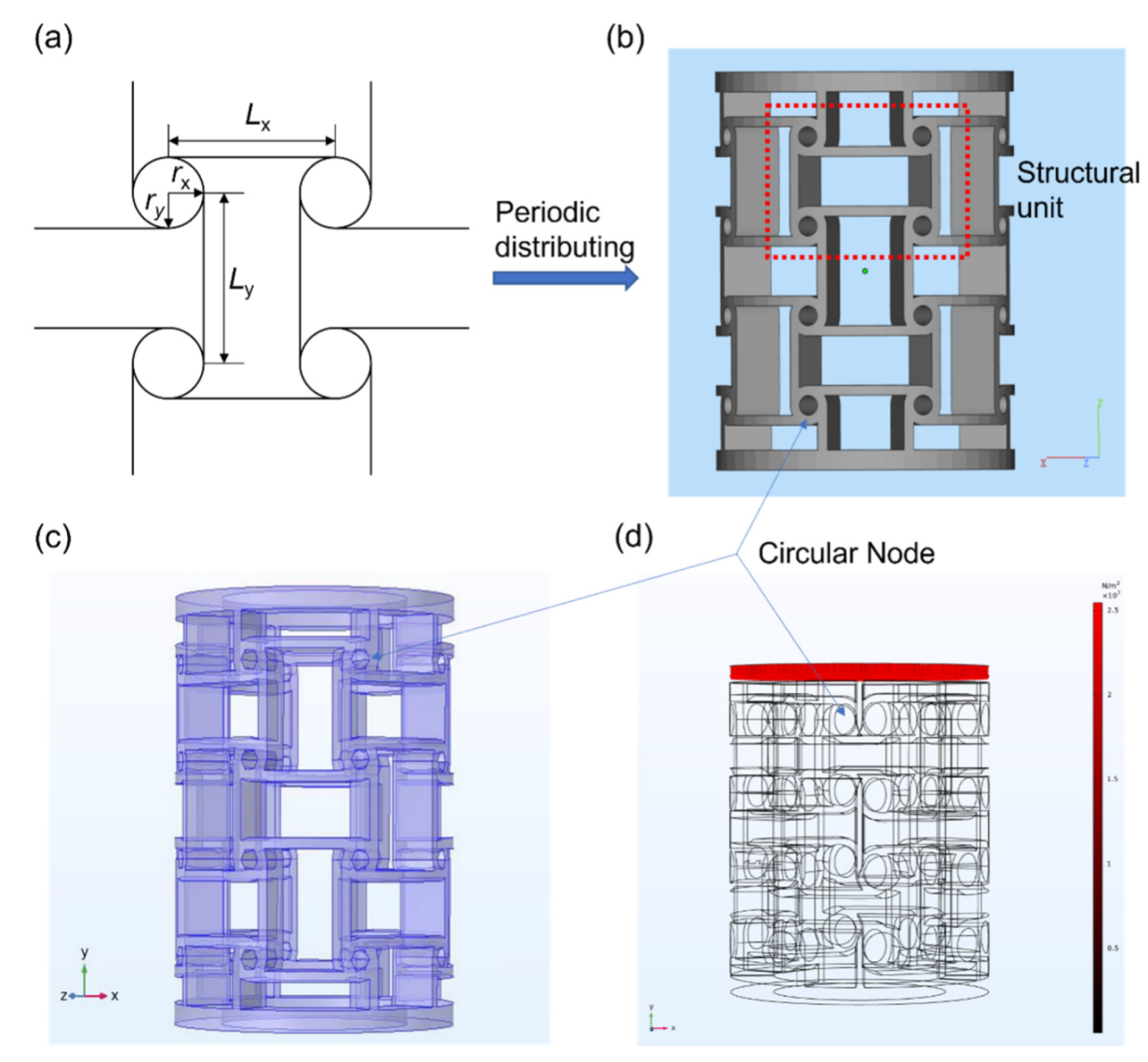
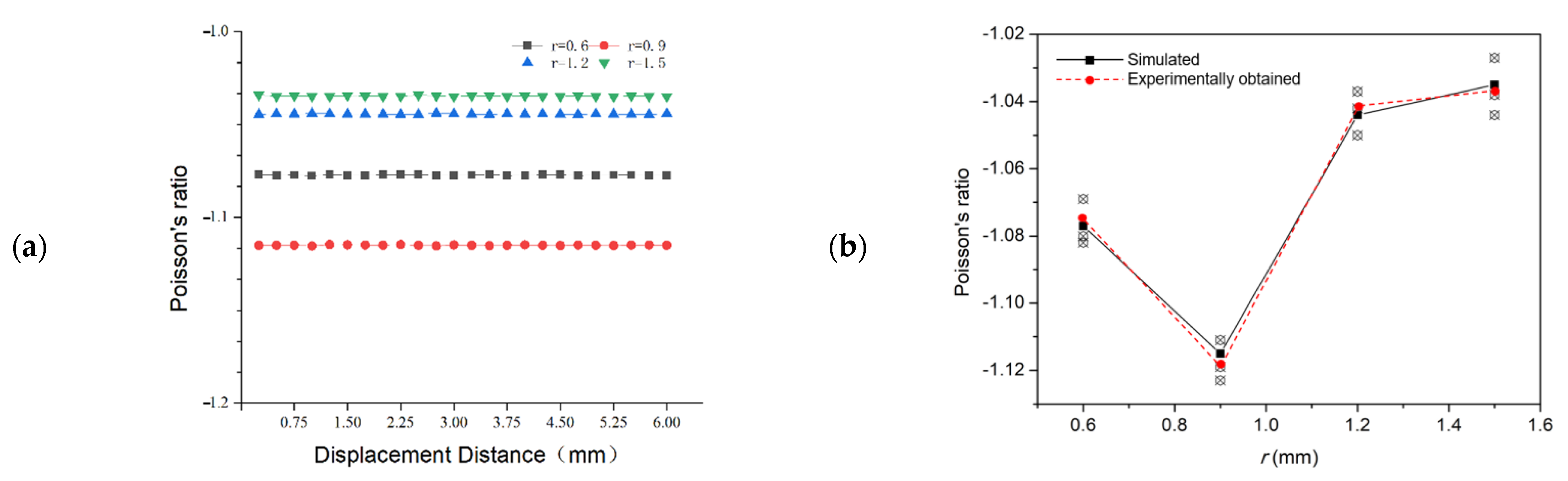
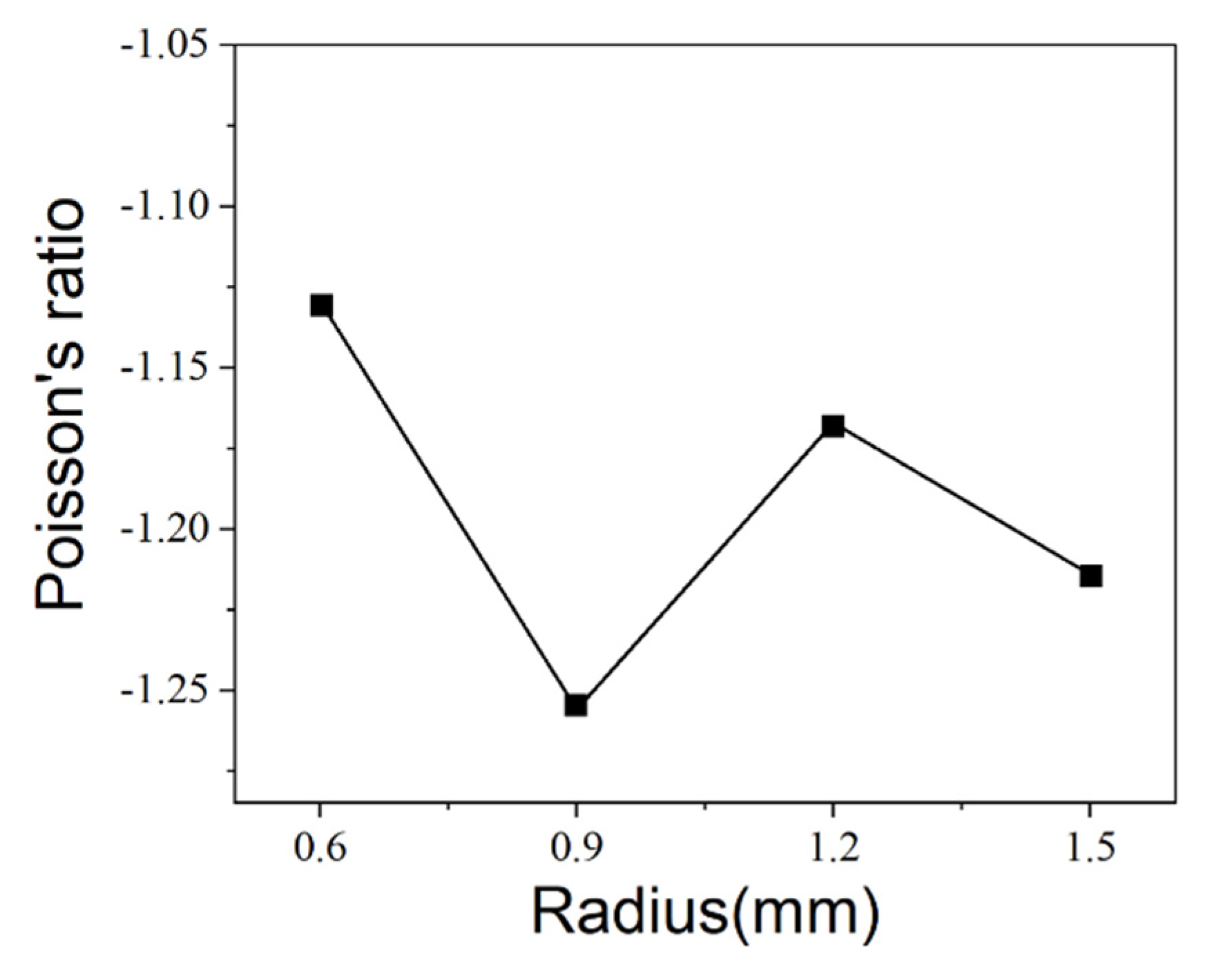
- All given anti-tetrachiral stent models possess a negative Poisson’s ratio when subjected to compression force. The stent with r of 0.9 mm has the largest absolute value of negative Poisson’s ratio. The upper and lower rings of the model have a suppressive effect on the overall shrinkage of the model, and the absolute value of the negative Poisson ratio increases when the rings are removed. However, the existence of the ring structure is not the reason for the Poisson ratio not being a constant.
- (2)
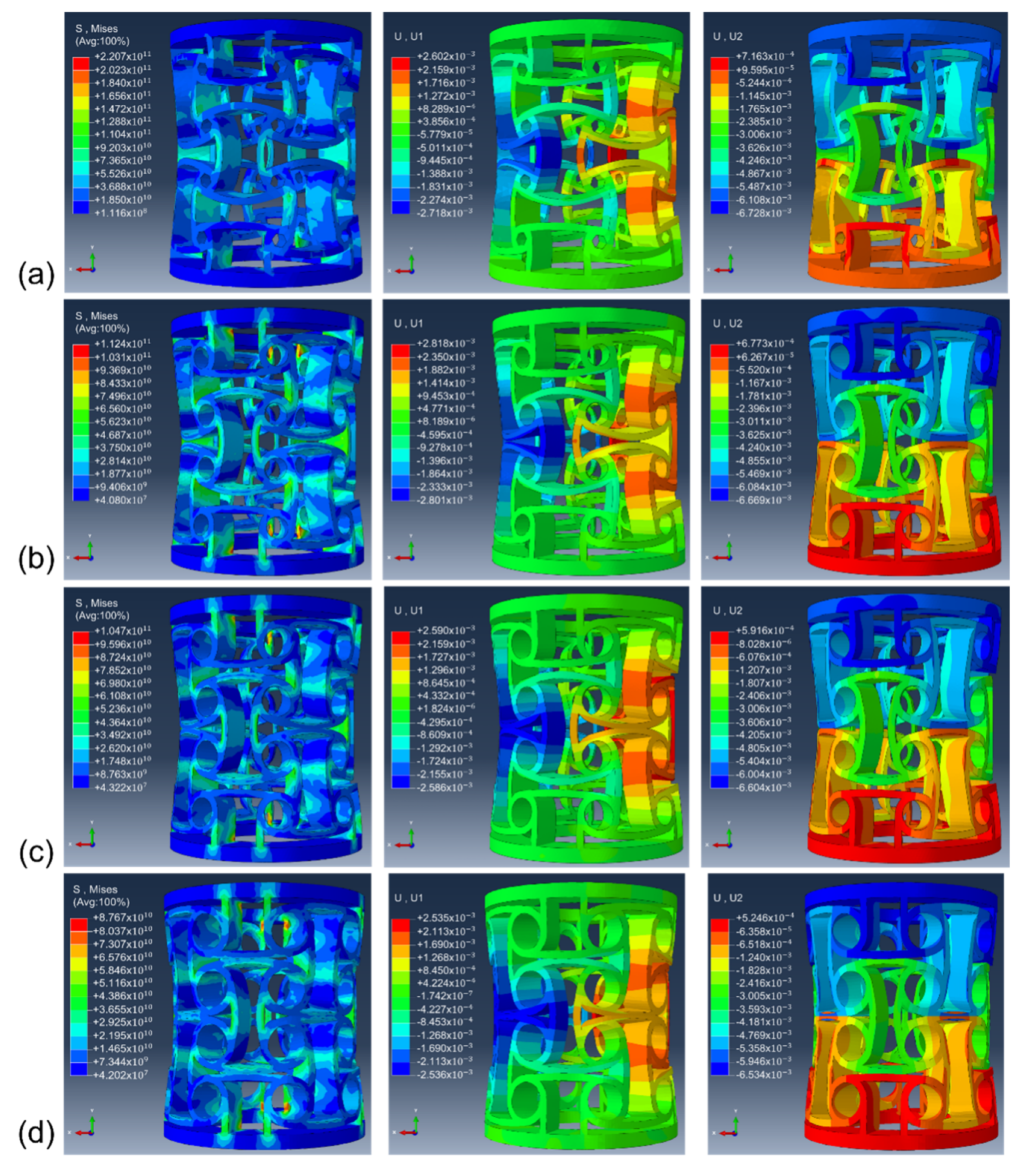
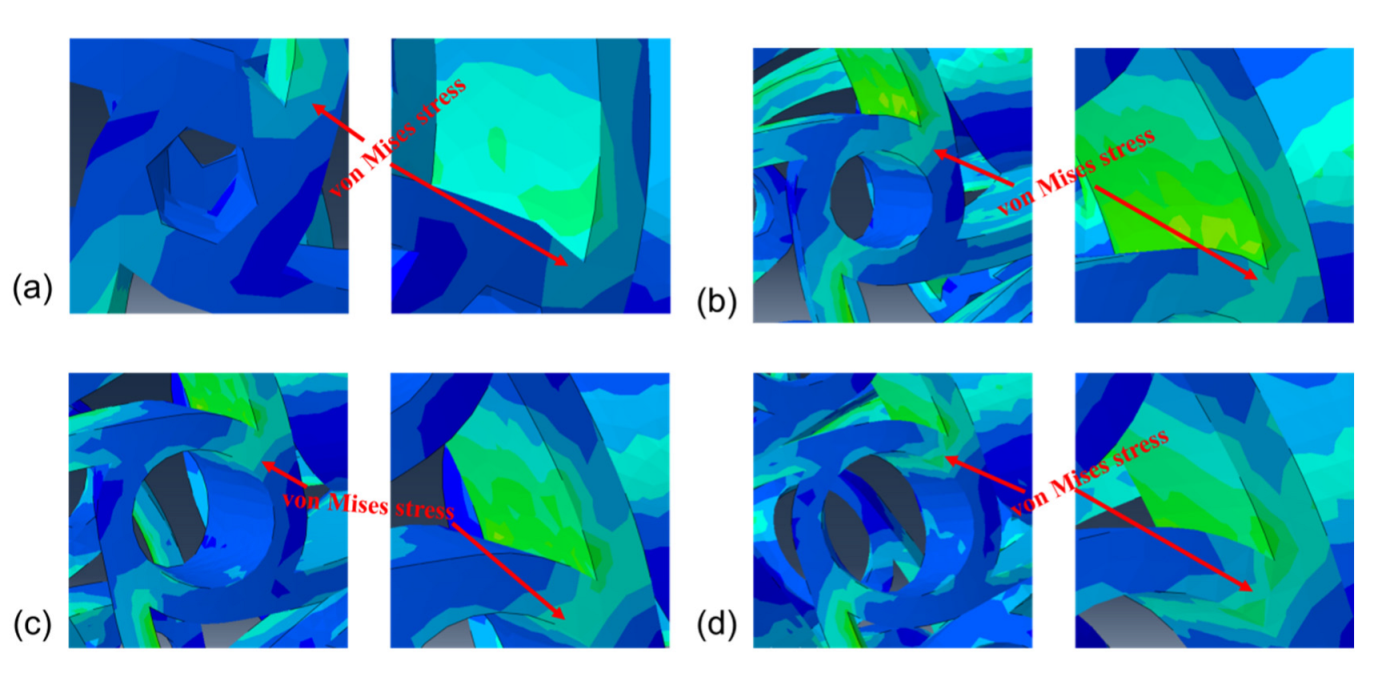
- As the node radius increases, the stress concentration phenomenon appears. Stress concentration causes the absolute value of Poisson’s ratio of the model to become smaller. The stress concentration phenomenon appeared least pronounced on the model with a 0.9 mm radius, followed by those with 0.6, 1.2, and 1.5 mm radii. The node radius of 0.9 mm had a larger absolute value of Poisson’s ratio because of the reduced stress concentration at the nodes and other unit connections.
- (3)
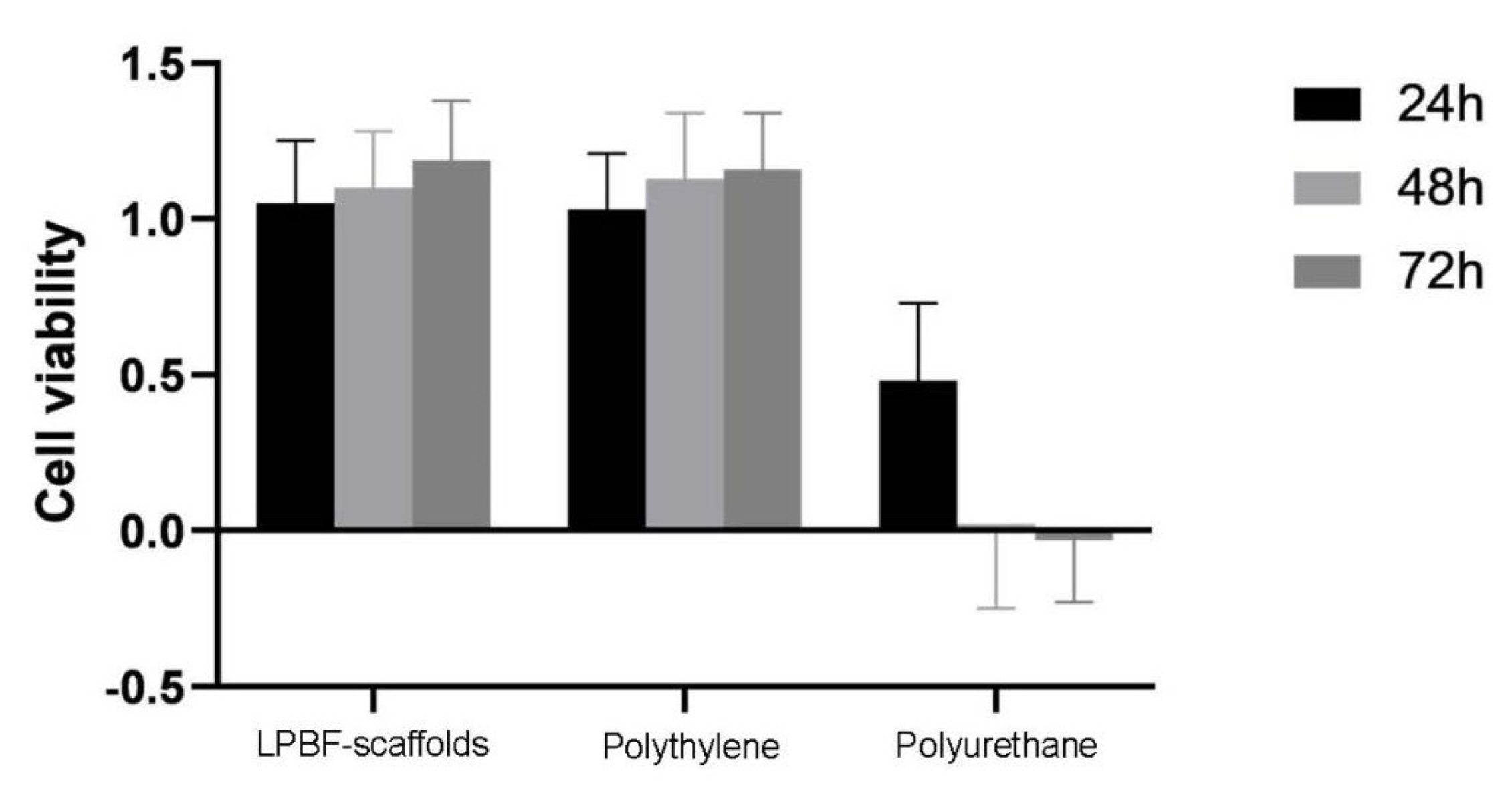
- The cultured cells showed good growth state on the LPBF-fabricated scaffolds. They demonstrated favorable structural, physical, and chemical stability and biocompatibility, indicating their promising potential for application in animal and clinical practice.
Author Contributions
Funding
Institutional Review Board Statement
Informed Consent Statement
Data Availability Statement
Acknowledgments
Conflicts of Interest
References
- Roth, G.A.; Dwyer-Lindgren, L.; Bertozzi-Villa, A.; Stubbs, R.W.; Morozoff, C.; Naghavi, M.; Mokdad, A.H.; Murray, C.J.L. Trends and Patterns of Geographic Variation in Cardiovascular Mortality Among US Counties, 1980–2014. JAMA 2017, 317, 1976–1992. [Google Scholar] [CrossRef] [PubMed]
- Lee, J.M.; Choi, K.H.; Koo, B.-K.; Park, J.; Kim, J.; Hwang, D.; Rhee, T.-M.; Kim, H.Y.; Jung, H.W.; Kim, K.-J.; et al. Prognostic Implications of Plaque Characteristics and Stenosis Severity in Patients With Coronary Artery Disease. J. Am. Coll. Cardiol. 2019, 73, 2413–2424. [Google Scholar] [CrossRef] [PubMed]
- Libby, P.; Buring, J.E.; Badimon, L.; Hansson, G.K.; Deanfield, J.; Bittencourt, M.S.; Tokgözoğlu, L.; Lewis, E.F. Atherosclerosis. Nat. Rev. Dis. Primers 2019, 5, 56. [Google Scholar] [CrossRef] [PubMed]
- Schneider, P.A.; Laird, J.R.; Doros, G.; Gao, Q.; Ansel, G.; Brodmann, M.; Micari, A.; Shishehbor, M.H.; Tepe, G.; Zeller, T. Mortality Not Correlated With Paclitaxel Exposure: An Independent Patient-Level Meta-Analysis of a Drug-Coated Balloon. J. Am. Coll. Cardiol. 2019, 73, 2550–2563. [Google Scholar] [CrossRef]
- Lookstein, R.A.; Haruguchi, H.; Ouriel, K.; Weinberg, I.; Lei, L.; Cihlar, S.; Holden, A. Drug-Coated Balloons for Dysfunctional Dialysis Arteriovenous Fistulas. N. Engl. J. Med. 2020, 383, 733–742. [Google Scholar] [CrossRef] [PubMed]
- Tepe, G.; Laird, J.; Schneider, P.; Brodmann, M.; Krishnan, P.; Micari, A.; Metzger, C.; Scheinert, D.; Zeller, T.; Cohen, D.J.; et al. Drug-coated balloon versus standard percutaneous transluminal angioplasty for the treatment of superficial femoral and popliteal peripheral artery disease: 12-month results from the IN.PACT SFA randomized trial. Circulation 2015, 131, 495–502. [Google Scholar] [CrossRef] [Green Version]
- Bausback, Y.; Wittig, T.; Schmidt, A.; Zeller, T.; Bosiers, M.; Peeters, P.; Brucks, S.; Lottes, A.E.; Scheinert, D.; Steiner, S. Drug-Eluting Stent Versus Drug-Coated Balloon Revascularization in Patients With Femoropopliteal Arterial Disease. J. Am. Coll. Cardiol. 2019, 73, 667–679. [Google Scholar] [CrossRef]
- Yang, X.; Yang, Y.; Guo, J.; Meng, Y.; Li, M.; Yang, P.; Liu, X.; Aung, L.H.H.; Yu, T.; Li, Y. Targeting the epigenome in in-stent restenosis: From mechanisms to therapy. Mol. Ther. Nucleic Acids 2021, 23, 1136–1160. [Google Scholar] [CrossRef]
- Byrne, R.A.; Joner, M.; Kastrati, A. Stent thrombosis and restenosis: What have we learned and where are we going? The Andreas Grüntzig Lecture ESC 2014. Eur. Heart J. 2015, 36, 3320–3331. [Google Scholar] [CrossRef] [Green Version]
- Slepicka, P.; Kasalkova, N.S.; Siegel, J.; Kolska, Z.; Bacakova, L.; Svorcik, V. Nano-structured and functionalized surfaces for cytocompatibility improvement and bactericidal action. Biotechnol. Adv. 2015, 33, 1120–1129. [Google Scholar] [CrossRef]
- Wu, X.; Yin, T.; Tian, J.; Tang, C.; Huang, J.; Zhao, Y.; Zhang, X.; Deng, X.; Fan, Y.; Yu, D.; et al. Distinctive effects of CD34- and CD133-specific antibody-coated stents on re-endothelialization and in-stent restenosis at the early phase of vascular injury. Regen. Biomater. 2015, 2, 87–96. [Google Scholar] [CrossRef] [PubMed] [Green Version]
- Yin, R.-X.; Yang, D.-Z.; Wu, J.-Z. Nanoparticle drug- and gene-eluting stents for the prevention and treatment of coronary restenosis. Theranostics 2014, 4, 175–200. [Google Scholar] [CrossRef] [PubMed] [Green Version]
- Torrado, J.; Buckley, L.; Durán, A.; Trujillo, P.; Toldo, S.; Valle Raleigh, J.; Abbate, A.; Biondi-Zoccai, G.; Guzmán, L.A. Restenosis, Stent Thrombosis, and Bleeding Complications: Navigating Between Scylla and Charybdis. J. Am. Coll. Cardiol. 2018, 71, 1676–1695. [Google Scholar] [CrossRef] [PubMed]
- Holy, E.W.; Jakob, P.; Eickner, T.; Camici, G.G.; Beer, J.H.; Akhmedov, A.; Sternberg, K.; Schmitz, K.-P.; Lüscher, T.F.; Tanner, F.C. PI3K/p110α inhibition selectively interferes with arterial thrombosis and neointima formation, but not re-endothelialization: Potential implications for drug-eluting stent design. Eur. Heart J. 2014, 35, 808–820. [Google Scholar] [CrossRef] [PubMed] [Green Version]
- Pant, S.; Limbert, G.; Curzen, N.P.; Bressloff, N.W. Multiobjective design optimisation of coronary stents. Biomaterials 2011, 32, 7755–7773. [Google Scholar] [CrossRef] [PubMed]
- MacTaggart, J.; Poulson, W.; Seas, A.; Deegan, P.; Lomneth, C.; Desyatova, A.; Maleckis, K.; Kamenskiy, A. Stent Design Affects Femoropopliteal Artery Deformation. Ann. Surg. 2019, 270, 180–187. [Google Scholar] [CrossRef]
- Stoeckel, D.; Bonsignore, C.; Duda, S. A survey of stent designs. Minim. Invasive Ther. Allied Technol. 2002, 11, 137–147. [Google Scholar] [CrossRef]
- Stergaard, M.B.; Hansen, S.R.; Januchta, K.; To, T.; Smedskjaer, M.M. Revisiting the Dependence of Poisson’s Ratio on Liquid Fragility and Atomic Packing Density in Oxide Glasses. Materials 2019, 12, 2439. [Google Scholar] [CrossRef] [Green Version]
- Scarpa, F.; Smith, C.W.; Ruzzene, M.; Wadee, M.K. Mechanical properties of auxetic tubular truss-like structures. Phys. Status Solidi (B) 2008, 245, 584–590. [Google Scholar] [CrossRef]
- Wu, W.; Song, X.; Liang, J.; Xia, R.; Qian, G.; Fang, D. Mechanical properties of anti-tetrachiral auxetic stents. Compos. Struct. 2018, 185, 381–392. [Google Scholar] [CrossRef]
- Zhang, W.; Zhang, B.; Xiao, H.; Yang, H.; Wang, Y.; Zhu, H. A Layer-Dependent Analytical Model for Printability Assessment of Additive Manufacturing Copper/Steel Multi-Material Components by Directed Energy Deposition. Micromachines 2021, 12, 1394. [Google Scholar] [CrossRef] [PubMed]
- Khalaj, R.; Tabriz, A.G.; Okereke, M.I.; Douroumis, D. 3D printing advances in the development of stents. Int. J. Pharm. 2021, 609, 121153. [Google Scholar] [CrossRef] [PubMed]
- Hua, W.; Mitchell, K.; Raymond, L.; Godina, B.; Zhao, D.; Zhou, W.; Jin, Y. Fluid Bath-Assisted 3D Printing for Biomedical Applications: From Pre-to Postprinting Stages. ACS Biomater. Sci. Eng. 2021, 7, 4736–4756. [Google Scholar] [CrossRef] [PubMed]
- Chua, K.; Khan, I.; Malhotra, R.; Zhu, D. Additive manufacturing and 3D printing of metallic biomaterials. Eng. Regen. 2021, 2, 288–299. [Google Scholar] [CrossRef]
- Yang, J.; Gu, D.; Lin, K.; Wu, L.; Zhang, H.; Guo, M.; Yuan, L. Laser additive manufacturing of cellular structure with enhanced compressive performance inspired by Al–Si crystalline microstructure. CIRP J. Manuf. Sci. Technol. 2021, 32, 26–36. [Google Scholar] [CrossRef]
- Ma, C.; Gu, D.; Lin, K.; Dai, D.; Xia, M.; Yang, J.; Wang, H. Selective laser melting additive manufacturing of cancer pagurus’s claw inspired bionic structures with high strength and toughness. Appl. Surf. Sci. 2019, 469, 647–656. [Google Scholar] [CrossRef]
- Chen, H.; Gu, D.; Xiong, J.; Xia, M. Improving additive manufacturing processability of hard-to-process overhanging structure by selective laser melting. J. Mater. Process. Technol. 2017, 250, 99–108. [Google Scholar] [CrossRef]
- Chen, H.; Gu, D.; Deng, L.; Lu, T.; Kühn, U.; Kosiba, K. Laser additive manufactured high-performance Fe-based composites with unique strengthening structure. J. Mater. Sci. Technol. 2021, 89, 242–252. [Google Scholar] [CrossRef]
- Xiong, J.; Gu, D.; Chen, H.; Dai, D.; Shi, Q. Structural optimization of re-entrant negative Poisson’s ratio structure fabricated by selective laser melting. Mater. Des. 2017, 120, 307–316. [Google Scholar] [CrossRef]
- Plaza, A.; Merino, B.; Del Olmo, N.; Ruiz-Gayo, M. The cholecystokinin receptor agonist, CCK-8, induces adiponectin production in rat white adipose tissue. Br. J. Pharmacol. 2019, 176, 2678–2690. [Google Scholar] [CrossRef] [Green Version]
- Li, C.R.; Li, L.; Cao, H.J.; Qin, L.; Long, J.; Lai, Y.X.; Wang, X.L.; Li, Y. In vitro biosafety assessment of PLGA/TCP/Mg porous scaffold for bone regeneration. Session Biomater. Implants. 2015, 78, 81. [Google Scholar]
- Bäcker, H.C.; Wu, C.H.; Krüger, D.; Gwinner, C.; Perka, C.; Hardt, S. Metal on Metal Bearing in Total Hip Arthroplasty and Its Impact on Synovial Cell Count. J. Clin. Med. 2020, 9, 3349. [Google Scholar] [CrossRef] [PubMed]
- United States Pharmacopeial Convention. Committee of Revision. USP XXII, or, NF XVII, or The United States Pharmacopeia, or, The National Formulary; US Pharmacopeial Convention: Rockville, MD, USA, 1990. [Google Scholar]
- Shu, C.; He, H.; Fan, B.-W.; Li, J.-H.; Wang, T.; Li, D.-Y.; Li, Y.-M.; He, H. Canine implant biocompatibility of vascular stents manufactured using metal injection molding. Trans. Nonferrous Met. Soc. China 2022, 32, 569–580. [Google Scholar] [CrossRef]
- Ablikim, Z.; Ablikim, G.; Zhu, Q.F.; Chen, T.; Gang, W.U.; Hua, Y.Y.; Wang, S.H.; Hospital, C.; Pharmacy, S.O. Preparation of five kinds of acellular fish skin matrices and in vitro toxicity analysis. Acad. J. Second Mil. Med. Univ. 2019, 12, 162–168. [Google Scholar]
- Fu, X.; Liu, P.; Zhao, D.; Yuan, B.; Zhang, X. Effects of Nanotopography Regulation and Silicon Doping on Angiogenic and Osteogenic Activities of Hydroxyapatite Coating on Titanium Implant. Int. J. Nanomed. 2020, 15, 4171–4189. [Google Scholar] [CrossRef] [PubMed]


| Material | Young’s Modulus(E) | Poisson Ratio | Yield Stress | Limit Stress | Limit Nominal Strain | Density |
|---|---|---|---|---|---|---|
| 316L stainless steel | 196,000 MPa | 0.3 | 205 MPa | 5151 MPa | 60% |
| Node Radius (mm) | Horizontal Displacement (cm) | Vertical Displacement (cm) |
|---|---|---|
| 0.6 | −0.272 | 0.673 |
| 0.9 | −0.280 | 0.670 |
| 1.2 | −0.259 | 0.660 |
| 1.5 | −0.254 | 0.653 |
| Radius (mm) | Horizontal Deformation (cm) | Vertical Deformation (cm) | Change Rate (%) |
|---|---|---|---|
| 0.6 | −0.272(with) | 0.673(with) | 3 |
| −0.283(without) | 0.719(without) | ||
| 0.9 | −0.280(with) | 0.670(with) | 8 |
| −0.301(without) | 0.717(without) | ||
| 1.2 | −0.259(with) | 0.660(with) | 12 |
| −0.297(without) | 0.679(without) | ||
| 1.5 | −0.254(with) | 0.653(with) | 15 |
| −0.289(without) | 0.650(without) |
| Level | Extent of Reaction | Morphology of Cultured Cells |
|---|---|---|
| 0 | None | Discrete intracytoplasmic volume, no cell lysis, no reduction of cell proliferation |
| 1 | Minor | Not more than 20% of the cells are round, loosely attached, and without cytoplasmic or morphological changes; occasional lysed cells are present; only slight inhibition of cell growth is observed |
| 2 | Mild | Not more than 50% of the cells are round, devoid of intracytoplasmic granules, no extensive cell lysis, not more than 50% growth inhibition observable |
| 3 | Moderate | Not more than 70% of the cell layers contain rounded cells or are lysed; cell layers not completely destroyed, but more than 50% cell growth inhibition may be observed |
| 4 | Severe | Nearly complete or complete destruction of cell layers |
Publisher’s Note: MDPI stays neutral with regard to jurisdictional claims in published maps and institutional affiliations. |
© 2022 by the authors. Licensee MDPI, Basel, Switzerland. This article is an open access article distributed under the terms and conditions of the Creative Commons Attribution (CC BY) license (https://creativecommons.org/licenses/by/4.0/).
Share and Cite
Chen, K.; Wan, H.; Fang, X.; Chen, H. Laser Additive Manufacturing of Anti-Tetrachiral Endovascular Stents with Negative Poisson’s Ratio and Favorable Cytocompatibility. Micromachines 2022, 13, 1135. https://doi.org/10.3390/mi13071135
Chen K, Wan H, Fang X, Chen H. Laser Additive Manufacturing of Anti-Tetrachiral Endovascular Stents with Negative Poisson’s Ratio and Favorable Cytocompatibility. Micromachines. 2022; 13(7):1135. https://doi.org/10.3390/mi13071135
Chicago/Turabian StyleChen, Ke, Haoran Wan, Xiang Fang, and Hongyu Chen. 2022. "Laser Additive Manufacturing of Anti-Tetrachiral Endovascular Stents with Negative Poisson’s Ratio and Favorable Cytocompatibility" Micromachines 13, no. 7: 1135. https://doi.org/10.3390/mi13071135