
A Review of Spatter in Laser Powder Bed Fusion Additive Manufacturing: In Situ Detection, Generation, Effects, and Countermeasures

 , , , , , and
Abstract
:1. Introduction
2. Laser Powder Bed Fusion Spatter In Situ Detection Device
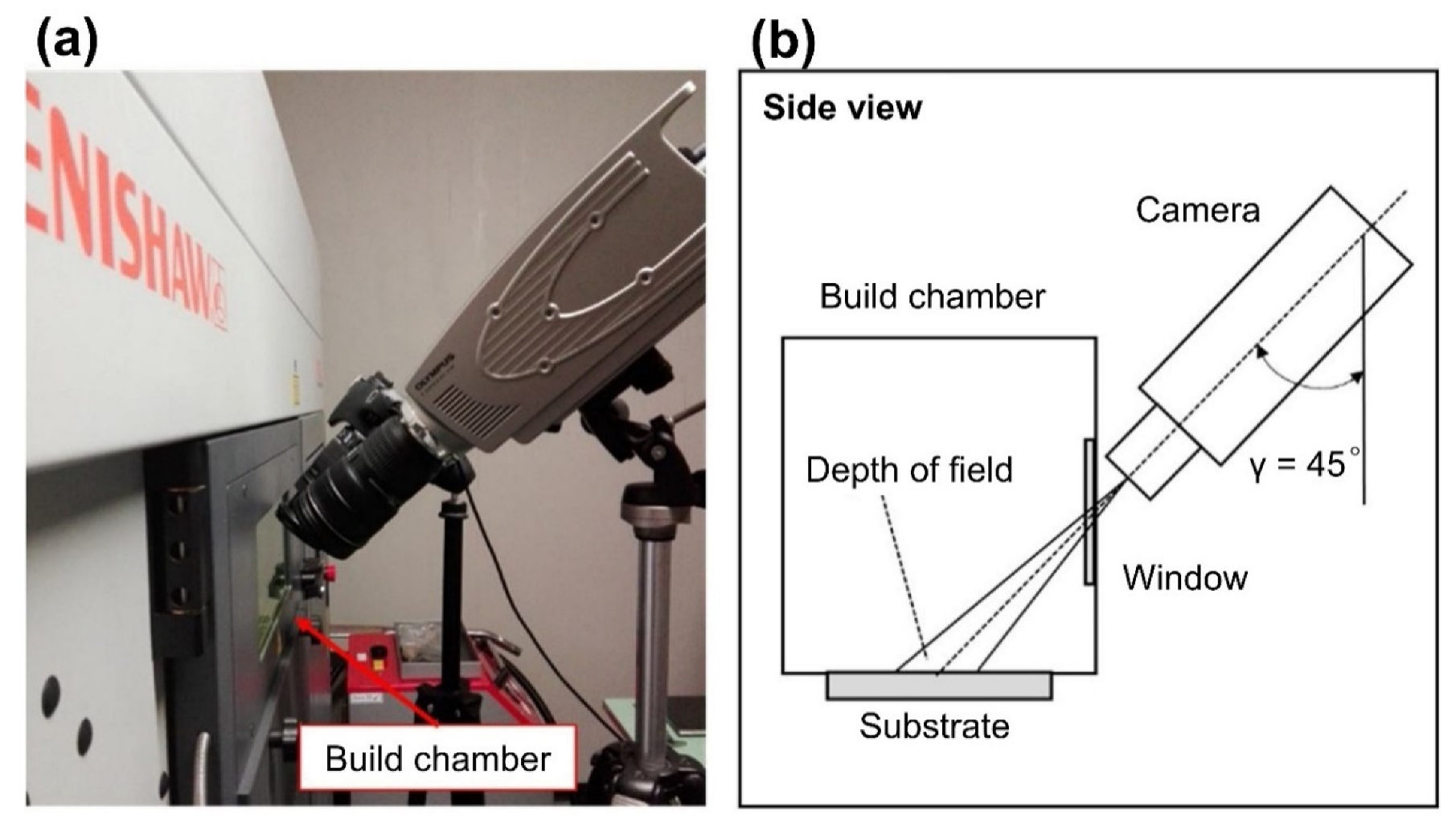
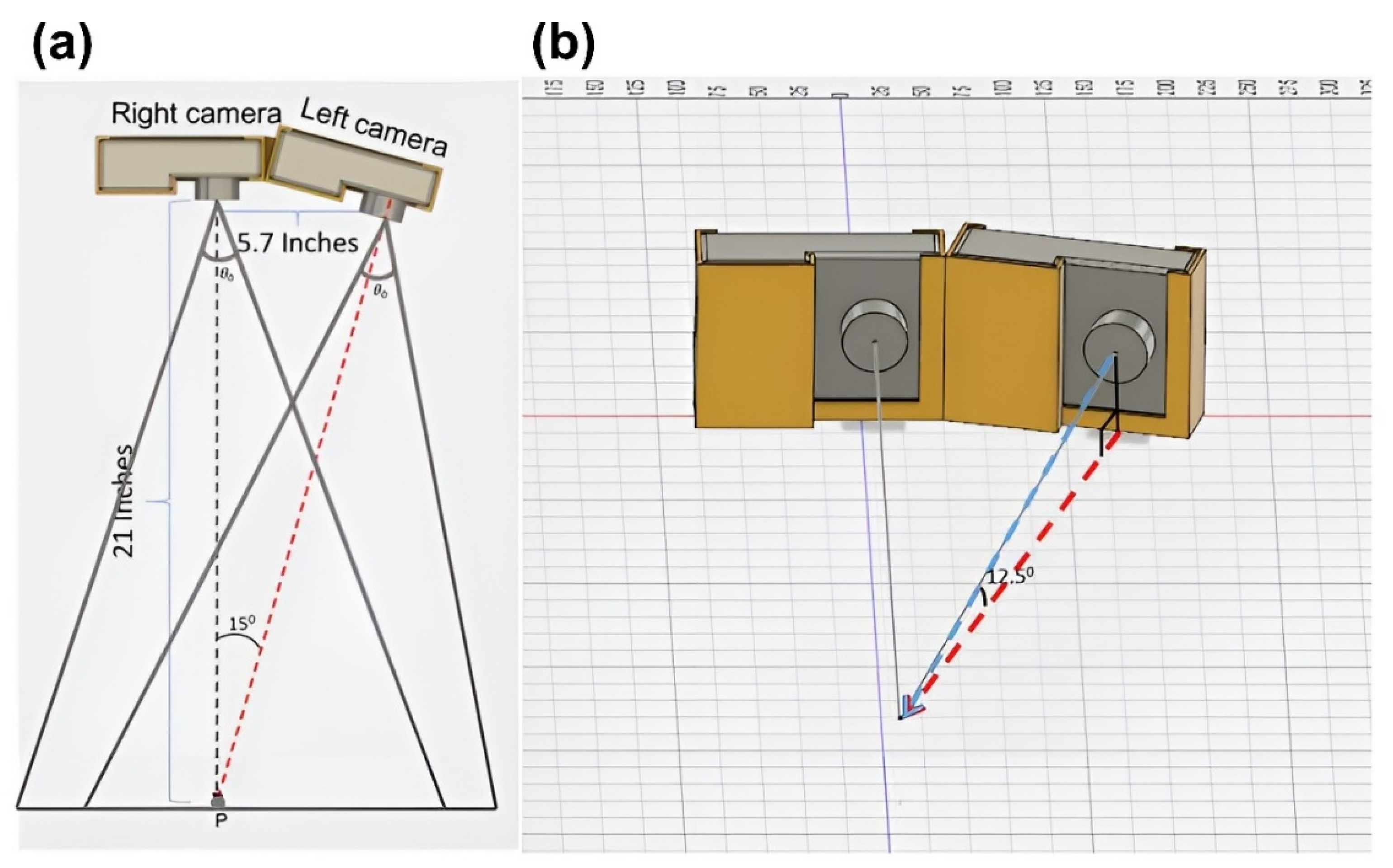
2.1. Visible-Light High-Speed Detector
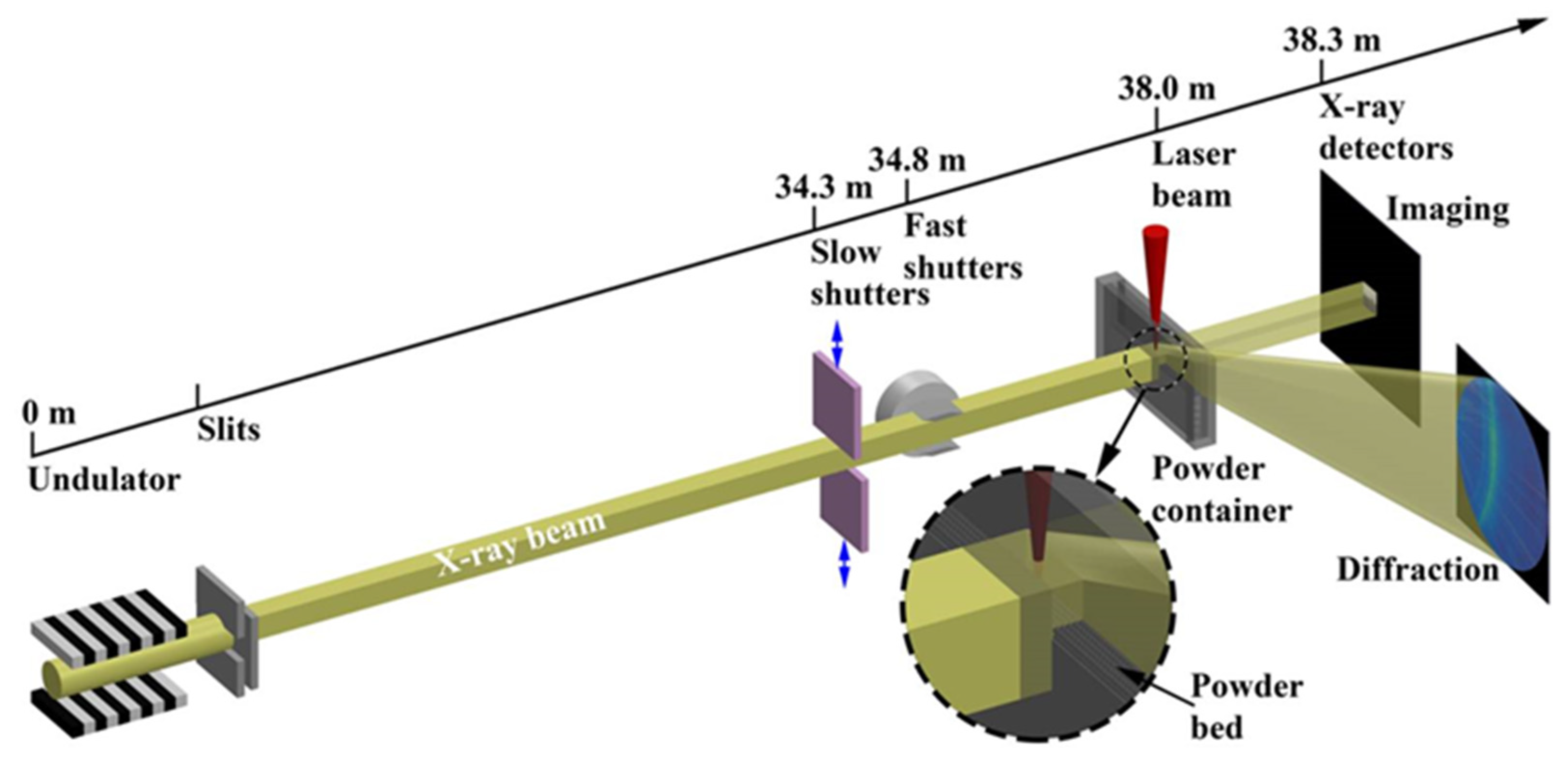
2.2. Invisible-Light In Situ Detection
2.3. Data Processing during Spatter Detection
2.3.1. Spatter 2D Image Processing Algorithm
2.3.2. Spatter 3D Image Processing Algorithm
2.4. Full-Cycle Detection of Spatter in L-PBF
- Initial stage (generation, adjacent to the melt pool): The positions of the generation of both the cold spatters and hot spatters are adjacent to the melt pool. The ultra-high-frame-rate in situ detection using a high-temporal-spatial-resolution off-axis camera combined with the illumination light source can obtain a clear morphology of spatters, which helps to reveal the mechanism of the spatter generation.
- Flight stage (ejection, away from the powder bed): The amount of spatter and the ejection angle significantly affect the internal defect of the part. The spatter trajectory, ejection velocity, ejection angle, and spatter size of the spatter should be obtained to investigate the intrinsic correlation between the spatter and the defect. A long monitoring time, high-frame-rate in situ detection system, along with the laser path using multi-sensors, is applied to capture the spatter flight (even with 3D information). The high-throughput data during L-PBF process can be used for the statistics analysis of spatter characterization. In general, only hot spatters are detected in this stage to reduce the processing pressure of the monitoring system.
- Fall-back stage (re-deposition, close to the powder bed): The spatter eventually redeposits on the powder bed and parts, which affect re-coating and part quality. A layer-by-layer in situ detection with a wide field-of-view and high-spatial-resolution camera can obtain high quality images of the powder and parts. The image data employing algorithms extract and confirm the size and location of the redeposited spatter, which helps in predicting the forming quality of the parts and the location of the defect.
2.5. Differences In Situ Detection between Spatter and Melt Pool
- (1)
- Compared with the detection of the melt pool, the spatter, with a micro size and extensive range of motion in the 3D space, is much more difficult to be detected, which requires multiple sensors, up to four sensors, with micron spatial resolution.
- (2)
- Additionally, the melt pool is generated by the action of the laser in the metal powder bed, and its trajectory can be predicted according to the pre-defined laser path. In contrast, the trajectory of spatter is hard to be predicted due to the high-speed random motion in the 3D space, which requires sensors with a higher temporal resolution up to microseconds to detect the whole process of motion trajectory deflection.
- (3)
- The data of spatter collected using sensors with high spatial resolution and high temporal resolution are several orders larger than the data of melt pool detection. Therefore, the data processing of spatter detection is more complex, which puts higher demands on the algorithm.
3. Mechanism of Spatter Generation
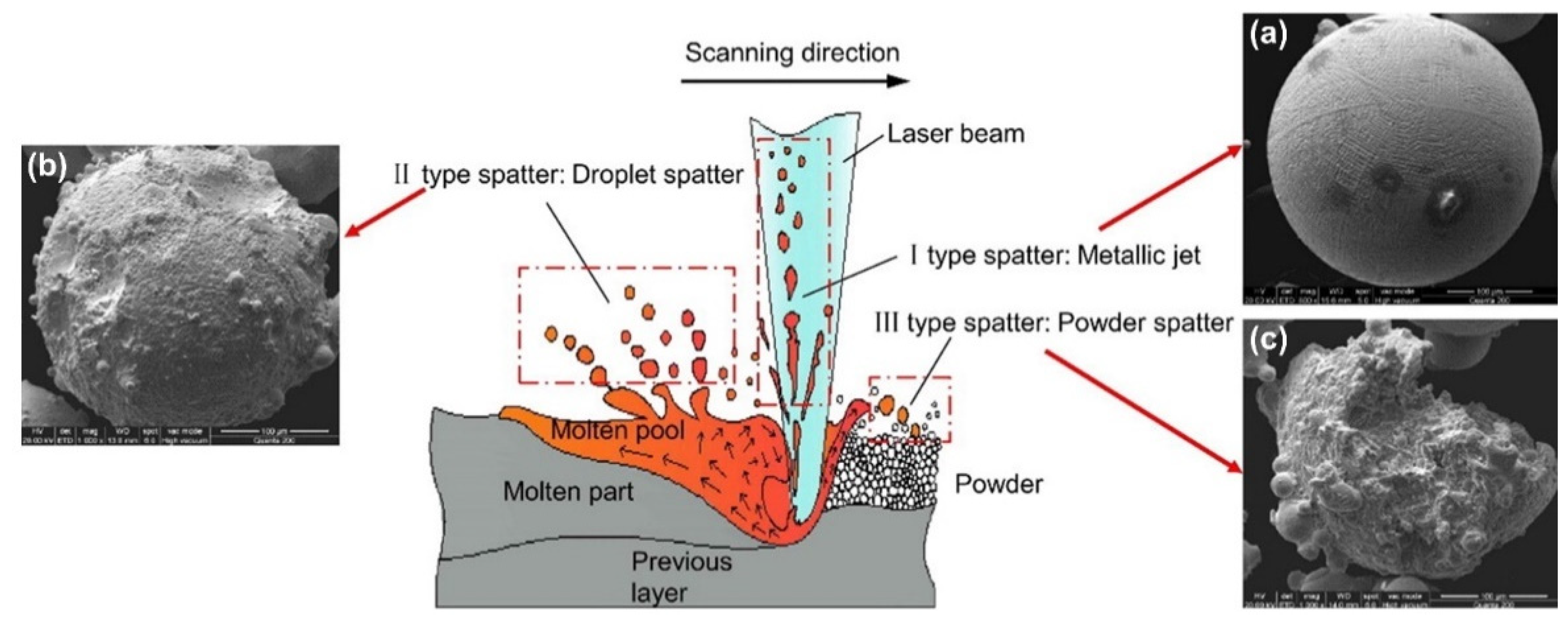
3.1. Spatter Classification
3.2. Study of Droplet Spatter Ejected from “Liquid Base” of Melt Pool
3.3. Study of Powder Spatter Ejected from “Solid Base” of Substrate
3.4. Study of Spatter Generation Mechanism in Multi-Laser-PBF Fabrication Process
4. Disadvantage of Spatter
4.1. Effect of Spatter on Printing Processing
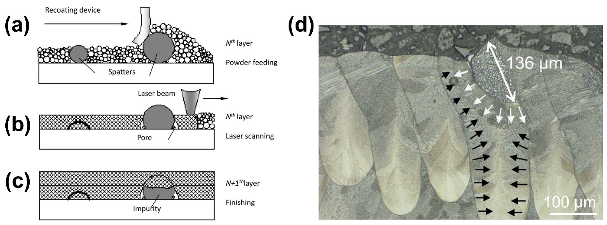
4.1.1. Effect of Spatter on Powder Re-Coating
4.1.2. Effect of Spatter on Energy Absorption
4.2. Effect of Spatter on Structure and Performance
4.3. Effect of Spatter on Powder Recycling
5. Spatter Countermeasures
5.1. Process Parameters
5.1.1. Laser VED
- Laser power: The laser power applied affects the number and volume of spatters, in most situations, studies have shown that the higher the laser power input, the more severe the spatter behavior. Andani et al. [52] concluded that decreasing the laser power would reduce spatter in L-PBF, and the laser power dominates the effect on spatter generation. Chen et al. [46] demonstrated that adjusting the power intensity and distribution of the laser beam to maintain the melt pool temperature between the melting and boiling points can significantly reduce spatter generation.
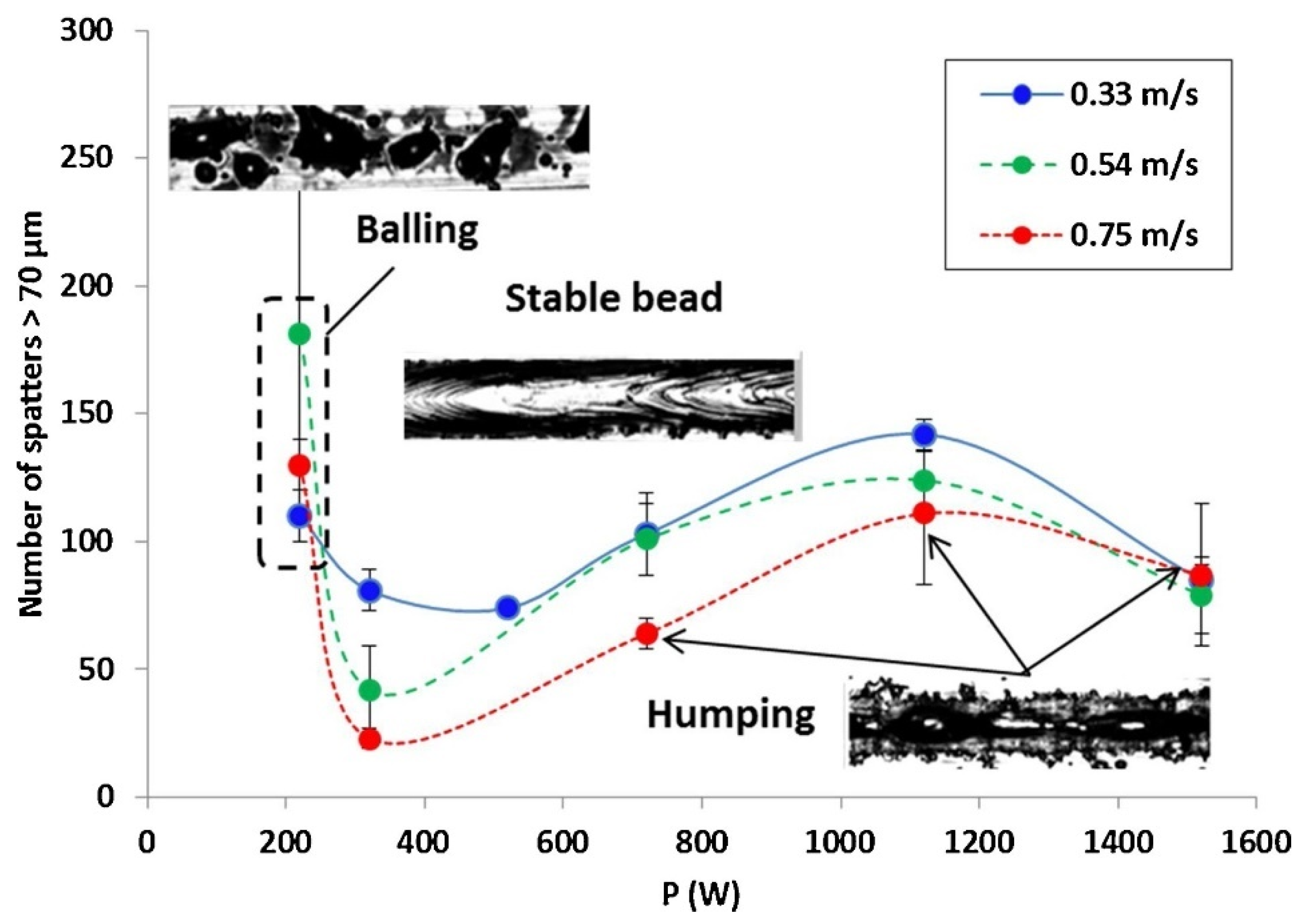
- Scanning velocity: The velocity of the laser scanning will affect the generation of spatter. Andani et al. [52] considered that increasing the laser scanning velocity would reduce spatter in L-PBF. Gunenthiram et al. [78] studied the number of spatters at different scanning velocities ( = 0.33~0.75 m/s) and found that the higher the scanning velocity, the less the number of hot spatters, as shown in Figure 22. However, a high scanning velocity leads to a longer scanning path, which increases the cold spatter caused by entrainment.
- Laser diameter: The laser spot size during L-PBF can significantly affect the melt dynamics and droplet spatter generation [117]. There are two reasons for the variation of the spot size: passive variation and active variation. For passive changes, the lens could be deformed due to thermal expansion and contraction induced by the incident high-energy laser, so that the spot size varies during laser conduction. The active variation is to adjust the spot size of the laser artificially. Gunenthiram et al. [78] demonstrated a possible way to entirely suppress the spatter by using a large spot when the melt pool is sufficiently deep. Sow et al. [116] investigated the influence of a large laser spot on L-PBF and concluded that combining a large spot with a low VED significantly improved the L-PBF in terms of the process stability, spatter reduction, and component density.
- Layer thickness: A high layer thickness results in a large amount of spatter. Schwerz et al. conducted experiments with layer thicknesses of 80 µm, 120 µm, and 150 µm, and found that the number of redeposited spatters increased with the layer thickness [82]. The heat of the melt pool cannot be conducted quickly by the surrounding powder as the layer thickness rises, which leads to the instability of the melt pool, and the number of spatters increases accordingly. However, due to the limited area of laser irradiation, the increase in the spatter will slow down when the layer thickness reaches a certain thickness. Zhang et al. [38] found that spatter generation slows down when the layer thickness exceeds twice the size of the powder particles.
5.1.2. Laser Mode
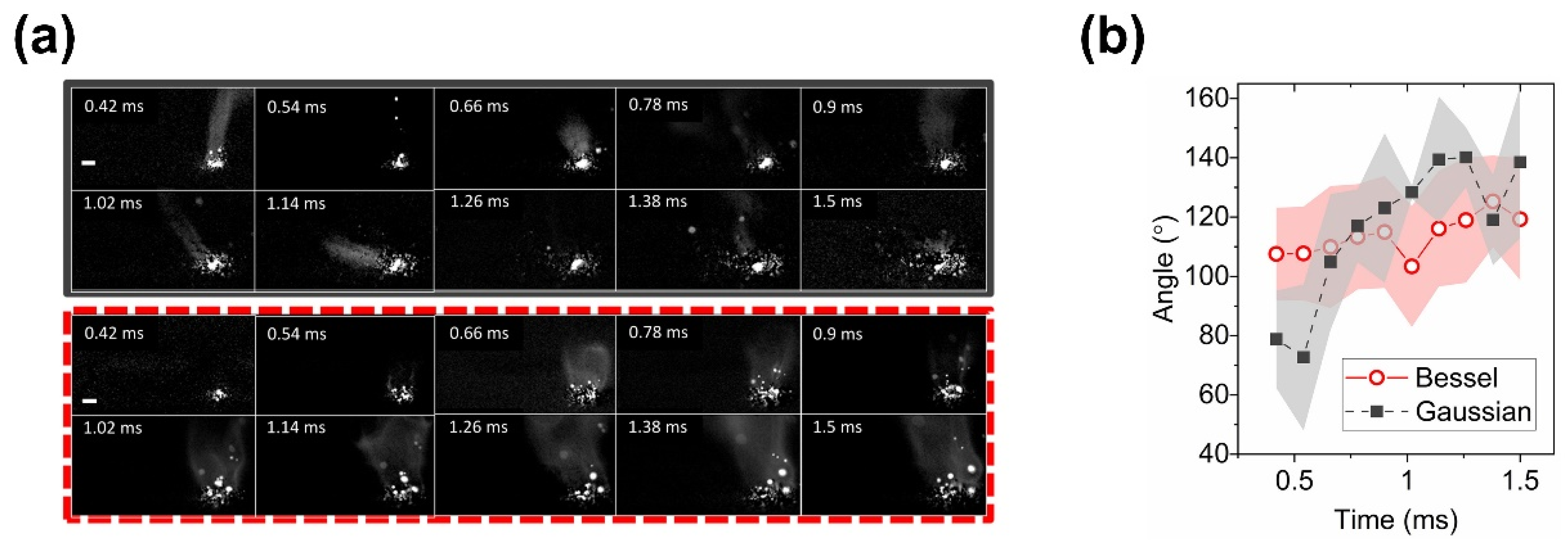
- Gaussian beam: Less spatter would be produced while printing with L-PBF equipment that uses Bessel beams. The Gaussian beam produces more spatter and the spatter is ejected at a higher velocity, this is due to the higher recoil forces generated by the Gaussian-like thermal distribution of the laser beam on the melt pool [129].
- Inverse Gaussian (annular) beams: Compared to the Gaussian beam, the inverse Gaussian (annular) can reduce the creation of spatter and increase the geometric tolerance of the 3D parts [119].
- Flat-top beam: L-PBF with a flat-top beam generates less and slower spatter than Gaussian beam and inverse Gaussian (annular) beams, as stated by Okunkova et al. [119].
- Bessel beam: The Bessel beam helps stabilize the melt pool to reduce spatter. Nguyen et al. [118] investigated the possibility of using Bessel beams for ultrafast laser processing in AM, indicating that Bessel beams might alleviate the negative impacts of spatter in L-PBF. Tumkur et al. [129], utilizing high-speed imaging to detect the dynamics of melt pool, found that Bessel beams stabilize the melt pool’s turbulence, increase their solidification times, and reduce spatter generation (Figure 23).
5.1.3. Printing Strategy
- Generation of spatter: Rivalta et al. [130] found that the hexagonal (outside-in verse) scanning strategy would produce more spatter. It is speculated that when hexagonal patterns are used for component manufacturing, the time between adjacent scan tracks rises, the temperature range becomes too wide, so more energy is required to heat the surrounding environment, resulting in increased spatter. A checkerboard scan approach can help to reduce the generation of spatter.
- Removal of spatter: The trajectory of the spatter is dependent on the direction of the laser scan. The movement trajectory of most spatters is opposite to the scanning direction. The spatter can be effectively removed if the direction of the spatter movement is consistent with the protective gas flow. However, the gas flow direction is determined by the design of the equipment, and the optimizing of the laser scanning direction can be performed. Effective spatter removal can be achieved by changing the direction of the laser scanning so that the trajectory of the spatter is consistent with the direction of the protecting gas flow. Anwar et al. [84] found that spatters re-depositioned near the outlet of the build chamber were greatly decreased when the laser scans were against the direction of the protective gas flow, but large particle spatters were still difficult to be removed [85,120].
5.1.4. Pressure of Build Chamber
5.1.5. Protective Gas
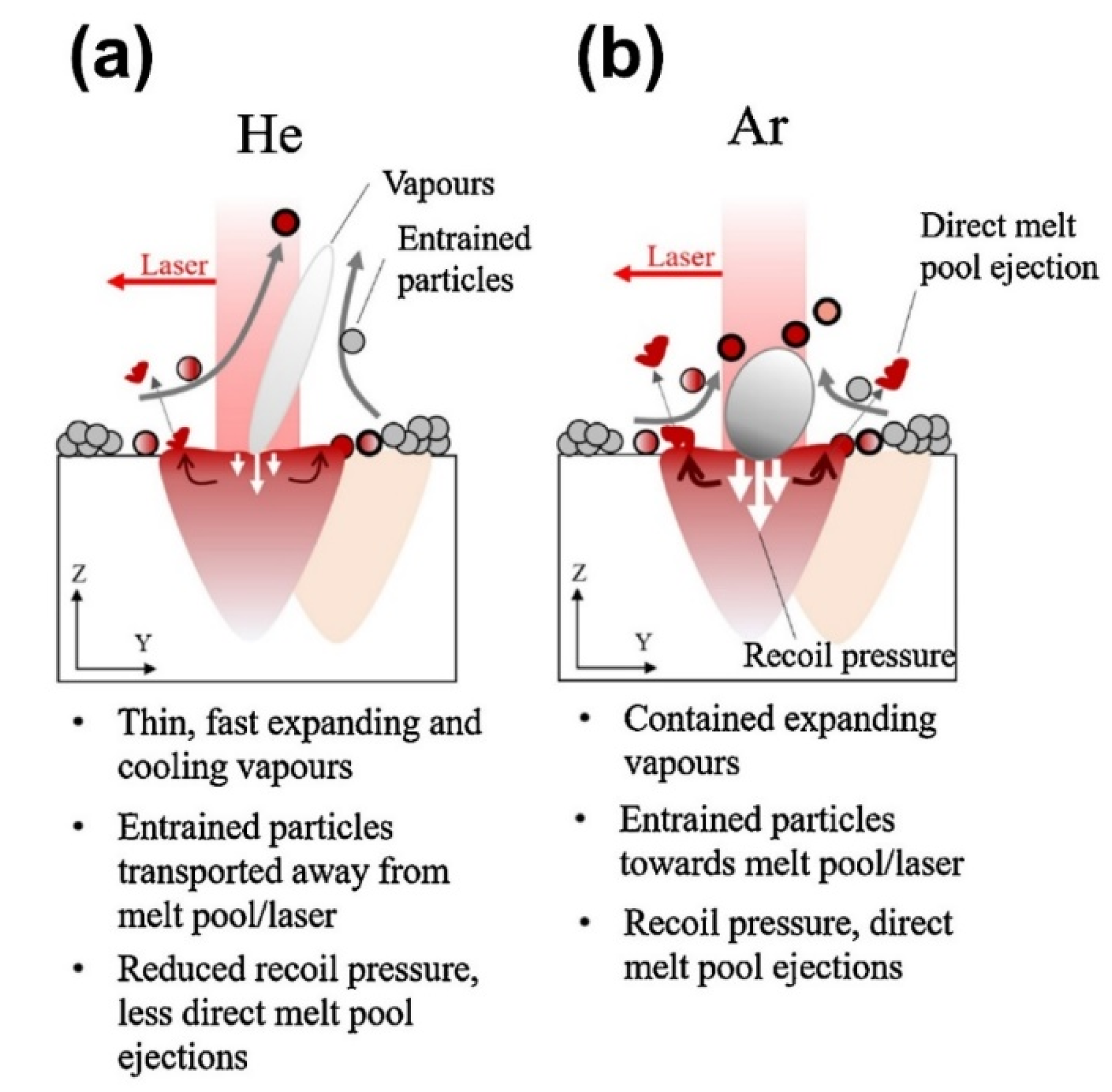
- Primary components of inert gases: Pauzon et al. [125] studied the effect of protective gas on L-PBF of Ti-6Al-4V powder in three different conditions: pure argon, pure helium, and a helium and argon mix (oxygen content was controlled at 100 ppm). In comparison to the common use of argon, studies have indicated that using pure helium or a mixture of helium and argon can reduce hot spatter by at least 60% and ~30%, respectively, as shown in Figure 25. No influence of different protective gases on the number of cold spatters was detected. The study also found that adding helium to the gas can help cool spatter more quickly, which is important for limiting powder-bed degradation throughout L-PBF.
- Secondary component of the inert gas: According to Wu et al. [124], the oxygen concentration in the protective environment increased considerably, resulting in the generation of spatter and an increase in the oxygen content of spatter during flight. By decreasing the oxygen level of the build chamber, the spatter generation can be reduced.
5.1.6. Gas Flow Strategies
5.2. Equipment and Materials for L-PBF
5.2.1. Research on L-PBF Equipment
5.2.2. Research on Powder Material
- Physical properties: High thermal conductivity and densification have a positive effect on spatter suppression. Due to the higher thermal conductivity of aluminum in the liquid state 316L, the laser energy can be rapidly dissipated into the substrate, limiting the vaporization of the aluminum alloy and the resulting spattering [78]. Gunenthiram et al. [78] pointed out that due to the densification effect, the melt pool will be located below the surface of the powder bed, which will inhibit the generation of spatter. The melt pools formed by the laser irradiation of different powder particles have varying viscosities which influence the generation of spatter. Leung et al. [140] investigated the laser–material interaction of 316L stainless steel powder and 13–93 bioactive glass powder during L-PBF at short time scales. The results indicate that droplet spatters are easily generated in a low-viscosity melt (e.g., 316L) because of the strong Marangoni-driven flow. By contrast, a high-viscosity melt (e.g., 13–93 bioactive glass) reduces spatter generation by dampening the Marangoni-driven flow.
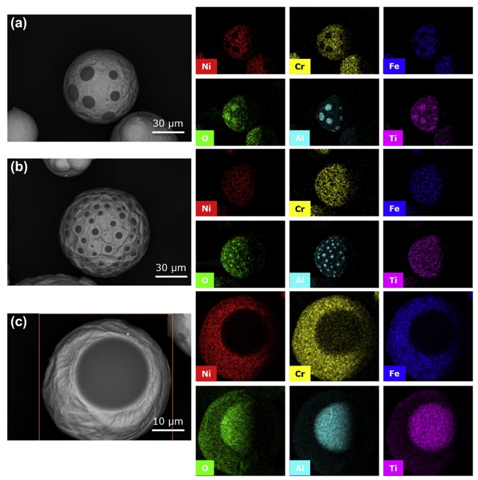
- Oxygen content: For the raw powder used in L-PBF, the higher the oxygen content, the greater the melt pool instability and the greater the probability of spattering. Fedina et al. [143] found that with the oxygen content of the powder rose, the number of spatters increased, whereas the other chemical elements remained relatively constant. They suggested that the increase in oxygen might have affected the powder spattering. Additionally, an increase in the powder oxygen content led to an increase in the oxygen content of the melt pool, which in turn affected the flow behavior of the fluid in the melt pool, leading to spattering as the melt pool broke into molten droplets [148]. Fedina et al. [142] investigated L-PBF dynamics and powder behavior by comparing water-atomized and gas-atomized powders. They discovered that the water-atomized powder had more frequent spatter ejection and speculated that the higher oxygen level in the powder caused the melt pool to become unstable, resulting in an excessive number of spatters.
6. Conclusions
- (1)
- In situ detection system for spatter during L-PBF: The detection methods are based on the physical properties (trajectory and brightness) of the spatter and melt pool. The variances in the trajectory and brightness lead to differences in the sensors and light sources of the detection system.
- Sensor: Due to the complex and unpredictable trajectories of the spatters in the 3D space compared to the melt pool, detection requires multiple sensors and sophisticated algorithms. A 3D detection solution with a quadruple-eye sensor combined with algorithms has been applied in a visible-light detection system. The emergence of 3D detection solutions provides more information in three dimensions, which improves the accuracy of the spatter detection.
- Light source: Compared to the bright high-temperature melt pool, the spatters consist of both bright hot droplet spatters and dark cold powder spatters. The motion of dark cold powder spatter can hardly be captured without an external light source. Therefore, a visible light source must be applied to enable the detecting of two types of spatters.
- (2)
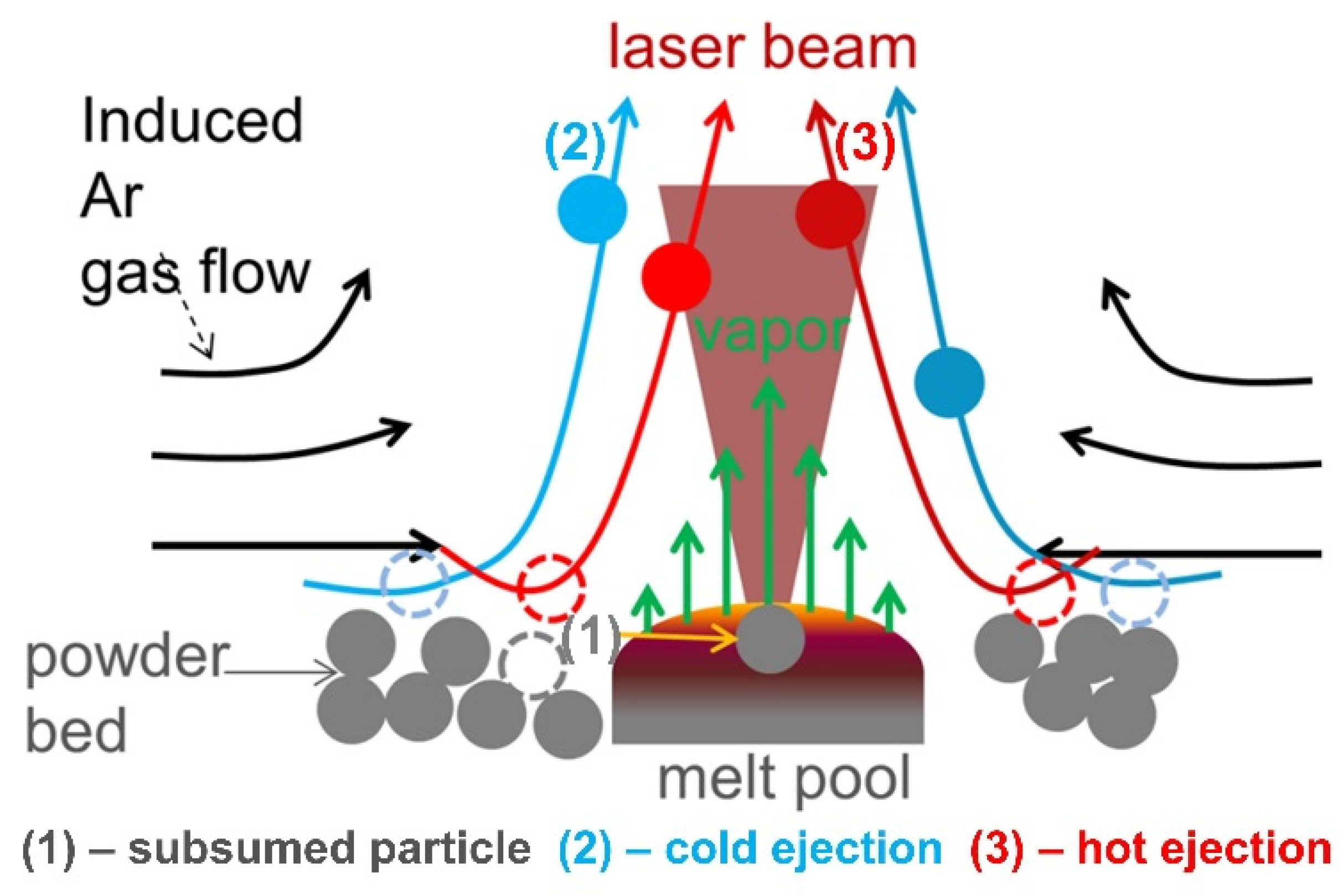
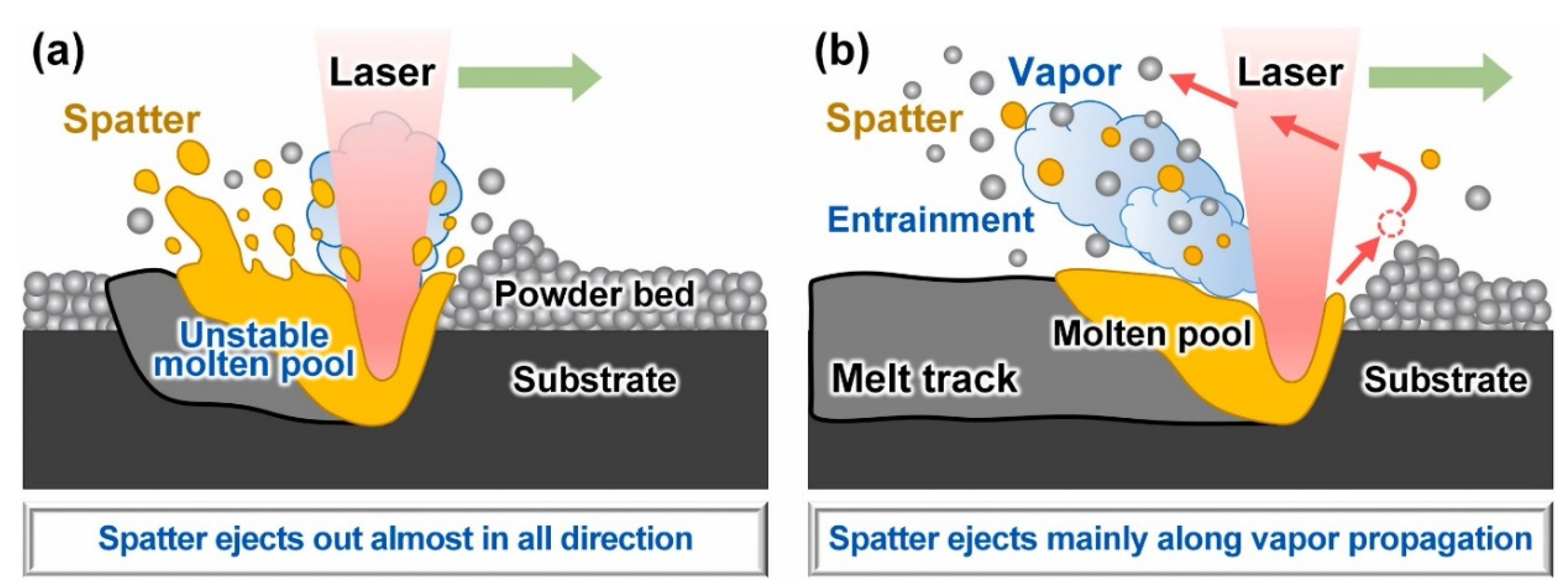
- Mechanism of spatter generation in L-PBF: spatter can be divided into droplet spatter from the “liquid base” of the melt pool and powder spatter from the “solid base” of the substrate.
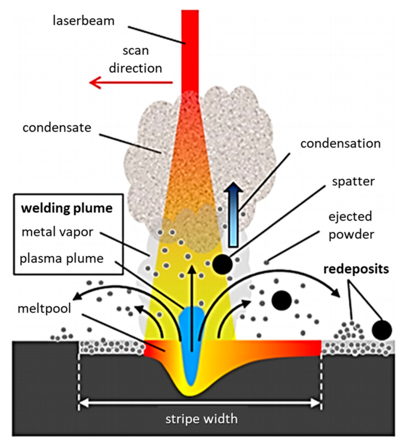
- Droplet spatter from the “Liquid base” of the melt pool: The droplet spatter originates from the instability of the melt pool. The Marangoni effect and the metal vapor recoil pressure generated on the surface of the melt pool lead to the spatter ejection from “liquid base” of the melt pool.
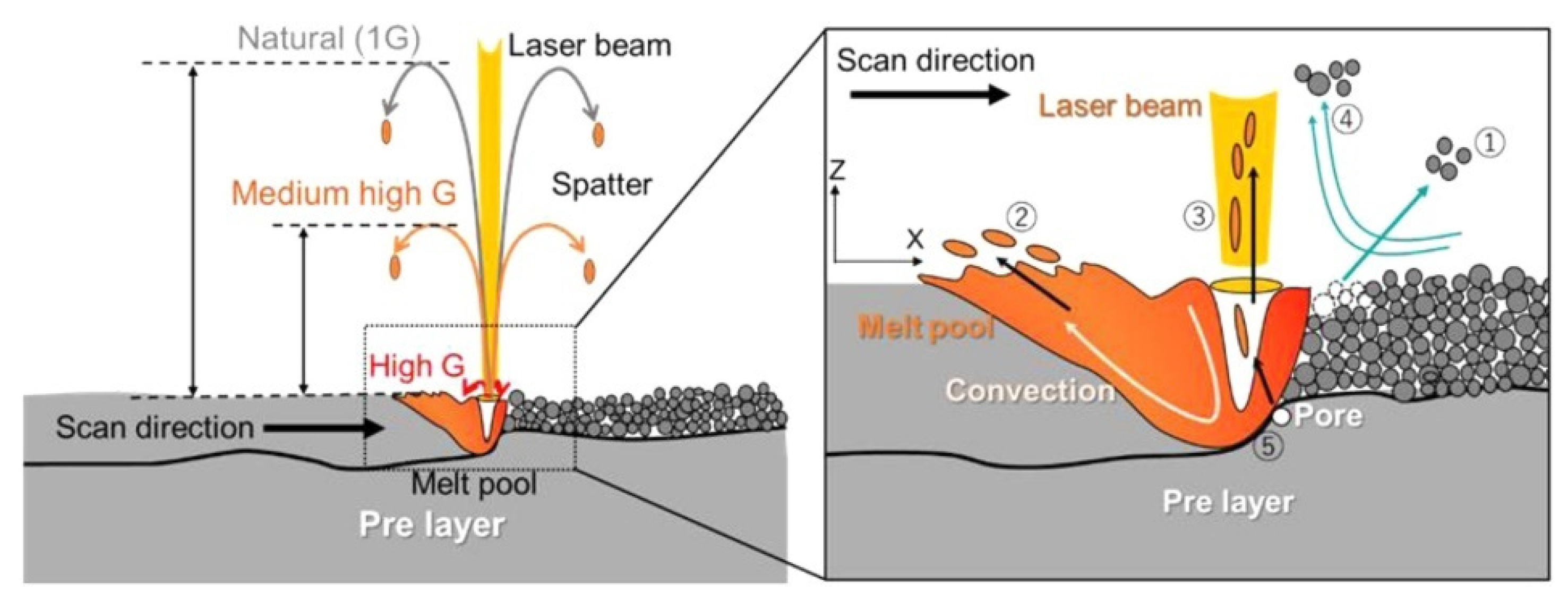
- Powder spatter from the “Solid base” of the substrate: Powder spatter is induced by the entrainment effect of the ambient gas flow driven by the metal vapor. A low-pressure area is generated near the high-speed moving metal vapor, and the surrounding inert protective gas will be “entrained” to the vicinity of the melt pool, driving the powder spatter to be ejected from the “solid base” of the substrate.
- (3)
- Spatter effects during L-PBF: Spatter has negative effects not only on the equipment and quality of parts, but also on the whole life cycle of the powder. Therefore, spatter significantly affects both the current L-PBF manufacturing and the subsequent L-PBF manufacturing.
- Equipment: the laser light path will be obstructed by the ejected spatter, and the scraper will be damaged by the redeposited spatter.
- Current L-PBF manufacturing: redeposited spatter can cause deterioration in the part structure and mechanical property.
- Subsequent L-PBF manufacturing: the spatters redeposit into the powder bed to be inclusions, resulting in a decrease in the quality of the re-cycle powder and affecting the subsequent L-PBF manufacturing.
- (4)
- Countermeasures for spatter in L-PBF: for the full cycle of spatter (generation–ejection–redeposition), the countermeasures for spatter are divided into spatter generation suppression and spatter removal.
- Spatter generation suppression: the generation of spatter can be suppressed by optimizing the laser volumetric energy density (e.g., raising the scanning velocity, lowering the laser power, decreasing the layer thickness, and increasing the laser spot), laser beam mode (Bessel beams), and pressure of the building chamber.
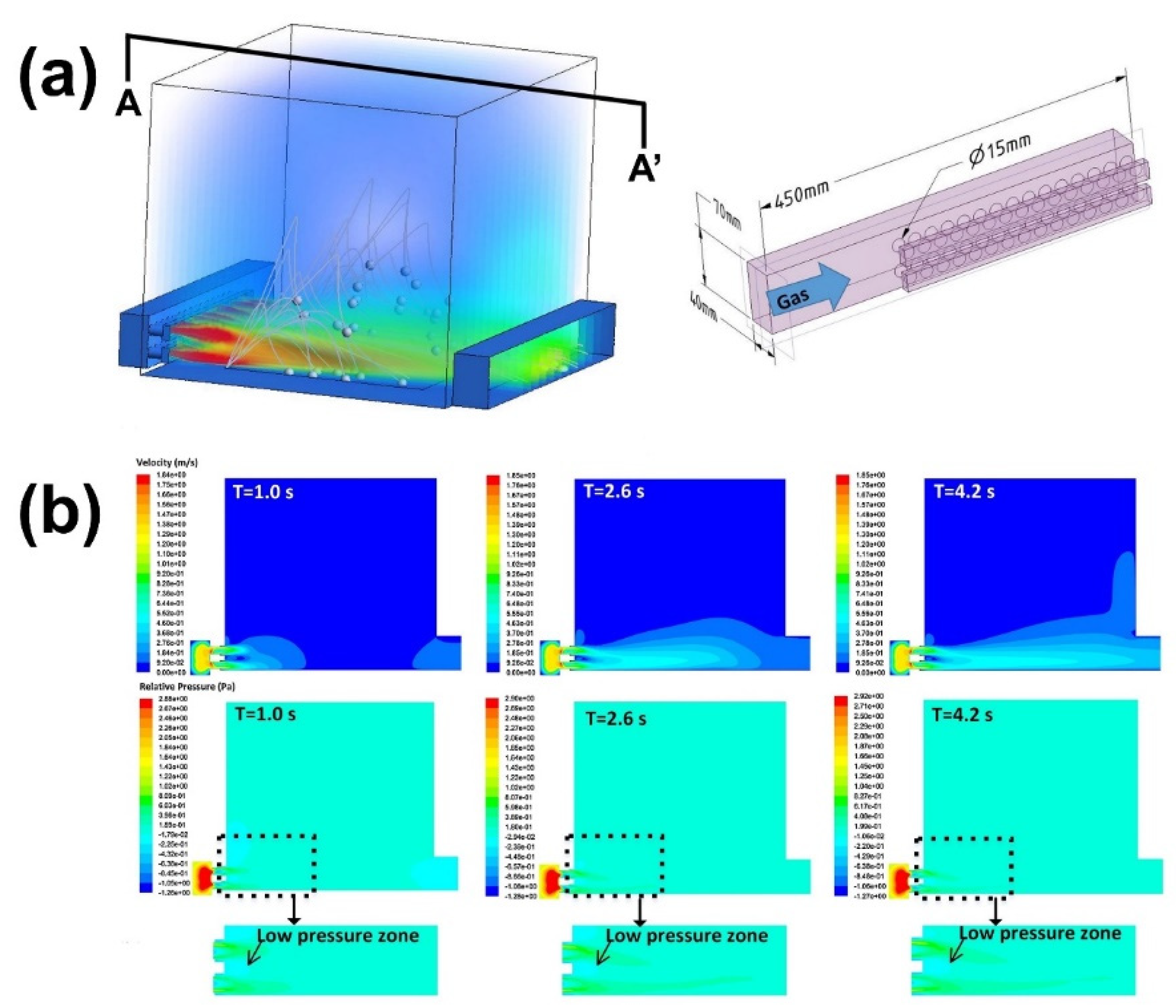
- Spatter removal efficiency: The gas flow removes process by-products from the process zone to enable an undisturbed process. Simulation framework methods (CFD and DEM) and a full-scale geometric model are employed to optimize the flow filed structure. A high-velocity gas flow under a certain value (counter-Coanda effect) applied in the center of the powder bed greatly improves the efficiency of spatter removal.
7. Future Research Directions
- (1)
- Study of spatter behavior under multiple lasers: Multi-laser synergy has been the main solution to achieve more efficient fabrication of large-sized parts. However, the mechanism of spatter becomes more complicated due to the enhancement of metal vapor, the Marangoni effect, and entrainment under the multi-laser interaction. Additionally, each laser induces both “liquid-based” and “solid-based” ejected spatters, and the amount of spatter increases dramatically using multiple lasers. The spatter is more difficult to be removed by gas flow due to the large-scaled build chamber. Therefore, the research of spatter in multi-beam manufacturing has become more urgent.
- (2)
- Improving the quality of in situ spatter detection: The combination of a visible-light high-speed camera and X-ray imaging technology in spatter detection coincides with the development trend of spatter detection [149]. The combination of the two methods enables us to study spatter behaviors from the inside (melt pool) to the outside (powder bed), and gain more information on the behaviors of the spatter. The multi-sensor system is indispensable in the research of spatter and the number of sensors can be expanded based on the existing quadruple-eye sensor.
- (3)
- Information processing using artificial intelligence: The data volume of the multi-sensor system could exponentially increase with the addition of data sources such as temperature, radiant intensity, light intensity information, acoustic signals, and images of melt pools and spatters. Therefore, machine learning (supervised, semi-supervised, unsupervised) is necessary for the efficient processing of the multi-source and heterogeneous data.
- (4)
- Countermeasures for spatter: At present, simulations are commonly used to study the countermeasures of spatter, and the raw data used in the simulations come from their detection. Improving the comprehensiveness and accuracy of detection information is conducive to the actual application of the simulation of spatter countermeasures.
- (5)
- Commercial L-PBF equipment: Several companies (e.g., Concept laser, EOS, SLM solutions) have developed systems for detecting melt pools during L-PBF manufacturing, but there is still a lack of spatter detection in the equipment. As a result of the complex spatter behaviors and serious negative impact in L-PBF, it is necessary to remove as much of the spatter as possible by using dynamical control of the protective gas flow field. The addition of an in situ spatter detection system enables the dynamical feedback of the control of the gas flow field.
Author Contributions
Funding
Acknowledgments
Conflicts of Interest
References
- DebRoy, T.; Mukherjee, T.; Wei, H.L.; Elmer, J.W.; Milewski, J.O. Metallurgy, mechanistic models and machine learning in metal printing. Nat. Rev. Mater. 2020, 6, 48–68. [Google Scholar] [CrossRef]
- Gu, D.; Shi, X.; Poprawe, R.; Bourell, D.L.; Setchi, R.; Zhu, J. Material-structure-performance integrated laser-metal additive manufacturing. Science 2021, 372, eabg1487. [Google Scholar] [CrossRef] [PubMed]
- MacDonald, E.; Wicker, R. Multiprocess 3D printing for increasing component functionality. Science 2016, 353, aaf2093. [Google Scholar] [CrossRef]
- Wei, H.; Mukherjee, T.; Zhang, W.; Zuback, J.; Knapp, G.; De, A.; DebRoy, T. Mechanistic models for additive manufacturing of metallic components. Prog. Mater. Sci. 2020, 116, 100703. [Google Scholar] [CrossRef]
- Office of the Under Secretary of Defense, Research and Engineering (USD(R&E)). Department of Defense Additive Manufacturing Strategy. Available online: https://www.cto.mil/dod-additive-manufacturing-strategy/ (accessed on 3 May 2022).
- U.S. Department of Defense. DoD Instruction 5000.93, “Use of Additive Manufacturing in the DoD”. Available online: https://www.defense.gov/News/News-Stories/Article/Article/2712969/dod-promotes-additive-manufacturing-expansion-standardization-training-through/ (accessed on 3 May 2022).
- National Science and Technology Information System, Public Service Platform. The 2022 Annual Project Application Guide for the Key Projects of Additive Manufacturing and Laser Manufacturing Under the 14th Five-Year National Key R&D Program. Available online: https://service.most.gov.cn/kjjh_tztg_all/20220427/4894.html (accessed on 3 May 2022).
- Yang, Y. Analysis of Classifications and Characteristic of Additive Manufacturing (3D Print). Adv. Aeronaut. Sci. Eng. 2019, 10, 309–318. (In Chinese) [Google Scholar]
- Lu, B.H.; Li, D.C. Development of the additive manufacturing (3D printing) technology. Mach. Build. Autom. 2013, 42, 1–4. (In Chinese) [Google Scholar]
- Ian Gibson, D.R. Brent Stucker. Additive Manufacturing Technologies 3D Printing, Rapid Prototyping, and Direct Digital Manufacturing; Springer: New York, NY, USA, 2015. [Google Scholar]
- Frazier, W.E. Metal additive manufacturing: A review. J. Mater. Eng. Perform. 2014, 23, 1917–1928. [Google Scholar] [CrossRef]
- Mellor, S.; Hao, L.; Zhang, D. Additive manufacturing: A framework for implementation. Int. J. Prod. Econ. 2014, 149, 194–201. [Google Scholar] [CrossRef]
- Zhang, L.; Li, Y.; Li, S.; Gong, P.; Chen, Q.; Geng, H.; Sun, M.; Sun, Q.; Hao, L. Fabrication of Titanium and Copper-Coated Diamond/Copper Composites via Selective Laser Melting. Micromachines 2022, 13, 724. [Google Scholar] [CrossRef]
- Wang, X.; Jiang, J.; Tian, Y. A Review on Macroscopic and Microstructural Features of Metallic Coating Created by Pulsed Laser Material Deposition. Micromachines 2022, 13, 659. [Google Scholar] [CrossRef]
- Xu, Z.; Wang, D.; Song, W.; Tang, C.; Sun, P.; Yang, J.; Hu, Q.; Zeng, X. Microstructure and Wear of W-Particle-Reinforced Al Alloys Prepared by Laser Melt Injection. Micromachines 2022, 13, 699. [Google Scholar] [CrossRef] [PubMed]
- Cardon, A.; Mareau, C.; Ayed, Y.; Van Der Veen, S.; Giraud, E.; Santo, P.D. Heat treatment simulation of Ti-6Al-4V parts produced by selective laser melting. Addit. Manuf. 2020, 39, 101766. [Google Scholar] [CrossRef]
- Bartlett, J.L.; Li, X. An overview of residual stresses in metal powder bed fusion. Addit. Manuf. 2019, 27, 131–149. [Google Scholar] [CrossRef]
- Grasso, M. In Situ Monitoring of Powder Bed Fusion Homogeneity in Electron Beam Melting. Materials 2021, 14, 7015. [Google Scholar] [CrossRef]
- Sun, S.; Brandt, M.; Easton, M. Powder bed fusion processes: An overview. Laser Addit. Manuf. 2017, 55–77. [Google Scholar]
- King, W.E.; Anderson, A.T.; Ferencz, R.M.; Hodge, N.E.; Kamath, C.; Khairallah, S.A.; Rubenchik, A.M. Laser powder bed fusion additive manufacturing of metals; physics, computational, and materials challenges. Appl. Phys. Rev. 2015, 2, 041304. [Google Scholar] [CrossRef]
- Ji, H.R.; Zhao, M.C.; Xie, B.; Zhao, Y.C.; Yin, D.F.; Gao, C.D.; Shuai, C.J.; Atrens, A. Corrosion and antibacterial performance of novel selective-laser-melted (SLMed) Ti-xCu biomedical alloys. J. Alloy. Compd. 2021, 864, 158415. [Google Scholar] [CrossRef]
- Aachen Center for Additive Manufacturing. Seminar 3D Printing with SLM – Challenges for Prediction of Deformation and Integration in Industrial Process Chains on 16 May 2017. Available online: https://acam.rwth-campus.com/news/seminar-3d-printing-with-slm-on-may-16-2017/ (accessed on 3 May 2022).
- Liu, Y.; Meng, J.; Zhu, L.; Chen, H.; Li, Z.; Li, S.; Wang, D.; Wang, Y.; Kosiba, K. Dynamic compressive properties and underlying failure mechanisms of selective laser melted Ti-6Al-4V alloy under high temperature and strain rate conditions. Addit. Manuf. 2022, 54, 102772. [Google Scholar] [CrossRef]
- Wang, W.; Takata, N.; Suzuki, A.; Kobashi, M.; Kato, M. Microstructural Variations in Laser Powder Bed Fused Al–15%Fe Alloy at Intermediate Temperatures. Materials 2022, 15, 4497. [Google Scholar] [CrossRef]
- Zhang, X.; Chueh, Y.-H.; Wei, C.; Sun, Z.; Yan, J.; Li, L. Additive manufacturing of three-dimensional metal-glass functionally gradient material components by laser powder bed fusion with in situ powder mixing. Addit. Manuf. 2020, 33, 101113. [Google Scholar] [CrossRef]
- Song, C.; Hu, Z.; Xiao, Y.; Li, Y.; Yang, Y. Study on Interfacial Bonding Properties of NiTi/CuSn10 Dissimilar Materials by Selective Laser Melting. Micromachines 2022, 13, 494. [Google Scholar] [CrossRef] [PubMed]
- Grasso, M.; Colosimo, B.M. Process defects and in situ monitoring methods in metal powder bed fusion: A review. Meas. Sci. Technol. 2017, 28, 044005. [Google Scholar] [CrossRef]
- Zhao, C.; Fezzaa, K.; Cunningham, R.W.; Wen, H.; De Carlo, F.; Chen, L.; Rollett, A.D.; Sun, T. Real-time monitoring of laser powder bed fusion process using high-speed X-ray imaging and diffraction. Sci. Rep. 2017, 7, 3602. [Google Scholar] [CrossRef]
- Fabbro, R. Melt pool and keyhole behaviour analysis for deep penetration laser welding. J. Phys. D Appl. Phys. 2010, 43, 445501. [Google Scholar] [CrossRef]
- Sames, W.J.; List, F.A.; Pannala, S.; Dehoff, R.R.; Babu, S.S. The metallurgy and processing science of metal additive manufacturing. Int. Mater. Rev. 2016, 61, 315–360. [Google Scholar] [CrossRef]
- Matthews, M.J.; Guss, G.; Khairallah, S.A.; Rubenchik, A.M.; Depond, P.J.; King, W.E. Denudation of metal powder layers in laser powder bed fusion processes. Acta Mater. 2016, 114, 33–42. [Google Scholar] [CrossRef]
- Yadroitsev, I.; Gusarov, A.; Yadroitsava, I.; Smurov, I. Single track formation in selective laser melting of metal powders. J. Mater. Process. Technol. 2010, 210, 1624–1631. [Google Scholar] [CrossRef]
- Riedlbauer, D.; Scharowsky, T.; Singer, R.F.; Steinmann, P.; Körner, C.; Mergheim, J. Macroscopic simulation and experimental measurement of melt pool characteristics in selective electron beam melting of Ti-6Al-4V. Int. J. Adv. Manuf. Technol. 2016, 88, 1309–1317. [Google Scholar] [CrossRef]
- Yin, J.; Wang, D.; Yang, L.; Wei, H.; Dong, P.; Ke, L.; Wang, G.; Zhu, H.; Zeng, X. Correlation between forming quality and spatter dynamics in laser powder bed fusion. Addit. Manuf. 2019, 31, 100958. [Google Scholar] [CrossRef]
- Bidare, P.; Bitharas, I.; Ward, R.; Attallah, M.; Moore, A.J. Laser powder bed fusion in high-pressure atmospheres. Int. J. Adv. Manuf. Technol. 2018, 99, 543–555. [Google Scholar] [CrossRef]
- Guo, Q.; Zhao, C.; Escano, L.I.; Young, Z.; Xiong, L.; Fezzaa, K.; Everhart, W.; Brown, B.; Sun, T.; Chen, L. Transient dynamics of powder spattering in laser powder bed fusion additive manufacturing process revealed by in-situ high-speed high-energy x-ray imaging. Acta Mater. 2018, 151, 169–180. [Google Scholar] [CrossRef]
- Grasso, M.; Colosimo, B. A statistical learning method for image-based monitoring of the plume signature in laser powder bed fusion. Robot. Comput. Manuf. 2018, 57, 103–115. [Google Scholar] [CrossRef]
- Zhang, W.; Ma, H.; Zhang, Q.; Fan, S. Prediction of powder bed thickness by spatter detection from coaxial optical images in selective laser melting of 316L stainless steel. Mater. Des. 2021, 213, 110301. [Google Scholar] [CrossRef]
- Repossini, G.; Laguzza, V.; Grasso, M.L.G.; Colosimo, B.M. On the use of spatter signature for in-situ monitoring of Laser Powder Bed Fusion. Addit. Manuf. 2017, 16, 35–48. [Google Scholar] [CrossRef]
- Tan, Z.; Fang, Q.; Li, H.; Liu, S.; Zhu, W.; Yang, D. Neural network based image segmentation for spatter extraction during laser-based powder bed fusion processing. Opt. Laser Technol. 2020, 130, 106347. [Google Scholar] [CrossRef]
- Yin, J.; Yang, L.; Yang, X.; Zhu, H.; Wang, D.; Ke, L.; Wang, Z.; Wang, G.; Zeng, X. High-power laser-matter interaction during laser powder bed fusion. Addit. Manuf. 2019, 29, 100778. [Google Scholar] [CrossRef]
- Luo, S.; Ma, X.; Xu, J.; Li, M.; Cao, L. Deep Learning Based Monitoring of Spatter Behavior by the Acoustic Signal in Selective Laser Melting. Sensors 2021, 21, 7179. [Google Scholar] [CrossRef]
- Barrett, C.; Carradero, C.; Harris, E.; McKnight, J.; Walker, J.; MacDonald, E.; Conner, B. Low cost, high speed stereovision for spatter tracking in laser powder bed fusion. In Proceedings of the 2018 International Solid Freeform Fabrication Symposium, Austin, TX, USA, 13–15 August 2018; pp. 2122–2134. [Google Scholar]
- Eschner, E.; Staudt, T.; Schmidt, M. 3D particle tracking velocimetry for the determination of temporally resolved particle trajectories within laser powder bed fusion of metals. Int. J. Extreme Manuf. 2019, 1, 035002. [Google Scholar] [CrossRef]
- Eschner, E.; Staudt, T.; Schmidt, M. Sensing approach for the in-situ determination of spatter motion within PBF-LB/M. CIRP Ann. 2022, 71, 149–152. [Google Scholar] [CrossRef]
- Chen, H.; Zhang, Y.; Giam, A.; Yan, W. Experimental and computational study on thermal and fluid behaviours of powder layer during selective laser melting additive manufacturing. Addit. Manuf. 2022, 52, 102645. [Google Scholar] [CrossRef]
- Zheng, H.; Wang, Y.; Xie, Y.; Yang, S.; Hou, R.; Ge, Y.; Lang, L.; Gong, S.; Li, H. Observation of Vapor Plume Behavior and Process Stability at Single-Track and Multi-Track Levels in Laser Powder Bed Fusion Regime. Metals 2021, 11, 937. [Google Scholar] [CrossRef]
- Wang, D.; Dou, W.; Ou, Y.; Yang, Y.; Tan, C.; Zhang, Y. Characteristics of droplet spatter behavior and process-correlated mapping model in laser powder bed fusion. J. Mater. Res. Technol. 2021, 12, 1051–1064. [Google Scholar] [CrossRef]
- Yang, D.; Li, H.; Liu, S.; Song, C.; Yang, Y.; Shen, S.; Lu, J.; Liu, Z.; Zhu, Y. In situ capture of spatter signature of SLM process using maximum entropy double threshold image processing method based on genetic algorithm. Opt. Laser Technol. 2020, 131, 106371. [Google Scholar] [CrossRef]
- Zhang, Y.; Soon, H.G.; Ye, D.; Fuh, J.Y.H.; Zhu, K. Powder-Bed Fusion Process Monitoring by Machine Vision With Hybrid Convolutional Neural Networks. IEEE Trans. Ind. Inform. 2019, 16, 5769–5779. [Google Scholar] [CrossRef]
- Zheng, H.; Li, H.; Lang, L.; Gong, S.; Ge, Y. Effects of scan speed on vapor plume behavior and spatter generation in laser powder bed fusion additive manufacturing. J. Manuf. Process. 2018, 36, 60–67. [Google Scholar] [CrossRef]
- Andani, M.T.; Dehghani, R.; Karamooz-Ravari, M.R.; Mirzaeifar, R.; Ni, J. A study on the effect of energy input on spatter particles creation during selective laser melting process. Addit. Manuf. 2018, 20, 33–43. [Google Scholar] [CrossRef]
- Ye, D.; Fuh, J.Y.H.; Zhang, Y.; Hong, G.S.; Zhu, K. In situ monitoring of selective laser melting using plume and spatter signatures by deep belief networks. ISA Trans. 2018, 81, 96–104. [Google Scholar] [CrossRef]
- Nassar, A.R.; Gundermann, M.A.; Reutzel, E.; Guerrier, P.; Krane, M.H.; Weldon, M.J. Formation processes for large ejecta and interactions with melt pool formation in powder bed fusion additive manufacturing. Sci. Rep. 2019, 9, 5038. [Google Scholar] [CrossRef]
- Cunningham, R.; Zhao, C.; Parab, N.; Kantzos, C.; Pauza, J.; Fezzaa, K.; Sun, T.; Rollett, A.D. Keyhole threshold and morphology in laser melting revealed by ultrahigh-speed x-ray imaging. Science 2019, 363, 849–852. [Google Scholar] [CrossRef]
- Young, Z.A.; Guo, Q.; Parab, N.D.; Zhao, C.; Qu, M.; Escano, L.I.; Fezzaa, K.; Everhart, W.; Sun, T.; Chen, L. Types of spatter and their features and formation mechanisms in laser powder bed fusion additive manufacturing process. Addit. Manuf. 2020, 36, 101438. [Google Scholar] [CrossRef]
- Leung, C.L.A.; Marussi, S.; Towrie, M.; Atwood, R.C.; Withers, P.J.; Lee, P.D. The effect of powder oxidation on defect formation in laser additive manufacturing. Acta Mater. 2018, 166, 294–305. [Google Scholar] [CrossRef]
- Bidare, P.; Bitharas, I.; Ward, R.M.; Attallah, M.M.; Moore, A.J. Fluid and particle dynamics in laser powder bed fusion. Acta Mater. 2018, 142, 107–120. [Google Scholar] [CrossRef]
- Grasso, M.L.G.; Demir, A.; Previtali, B.; Colosimo, B. In situ monitoring of selective laser melting of zinc powder via infrared imaging of the process plume. Robot. Comput. Manuf. 2018, 49, 229–239. [Google Scholar] [CrossRef]
- Grasso, M.; Laguzza, V.; Semeraro, Q.; Colosimo, B.M. In-Process Monitoring of Selective Laser Melting: Spatial Detection of Defects Via Image Data Analysis. J. Manuf. Sci. Eng. 2016, 139, 051001. [Google Scholar] [CrossRef]
- Yin, J.; Hao, L.; Yang, L.; Li, Y.; Li, Z.; Sun, Q.; Shi, B. Investigation of Interaction between Vapor Plume and Spatter Behavior during Selective Laser Melting Additive Manufacturing. Chin. J. Lasers 2022, 49, 1402010. (In Chinese) [Google Scholar]
- Liu, Y.; Yang, Y.; Mai, S.; Wang, D.; Song, C. Investigation into spatter behavior during selective laser melting of AISI 316L stainless steel powder. Mater. Des. 2015, 87, 797–806. [Google Scholar] [CrossRef]
- Wang, D.; Wu, S.; Fu, F.; Mai, S.; Yang, Y.; Liu, Y.; Song, C. Mechanisms and characteristics of spatter generation in SLM processing and its effect on the properties. Mater. Des. 2017, 117, 121–130. [Google Scholar] [CrossRef]
- Ly, S.; Rubenchik, A.M.; Khairallah, S.A.; Guss, G.; Matthews, M.J. Metal vapor micro-jet controls material redistribution in laser powder bed fusion additive manufacturing. Sci. Rep. 2017, 7, 4085. [Google Scholar] [CrossRef]
- Raza, A.; Pauzon, C.; Hryha, E.; Markström, A.; Forêt, P. Spatter oxidation during laser powder bed fusion of Alloy 718: Dependence on oxygen content in the process atmosphere. Addit. Manuf. 2021, 48, 102369. [Google Scholar] [CrossRef]
- Gasper, A.; Szost, B.; Wang, X.; Johns, D.; Sharma, S.; Clare, A.; Ashcroft, I. Spatter and oxide formation in laser powder bed fusion of Inconel 718. Addit. Manuf. 2018, 24, 446–456. [Google Scholar] [CrossRef]
- Yang, T.; Liu, T.; Liao, W.; MacDonald, E.; Wei, H.; Zhang, C.; Chen, X.; Zhang, K. Laser powder bed fusion of AlSi10Mg: Influence of energy intensities on spatter and porosity evolution, microstructure and mechanical properties. J. Alloy. Compd. 2020, 849, 156300. [Google Scholar] [CrossRef]
- Khairallah, S.A.; Anderson, A.T.; Rubenchik, A.; King, W.E. Laser powder-bed fusion additive manufacturing: Physics of complex melt flow and formation mechanisms of pores, spatter, and denudation zones. Acta Mater. 2016, 108, 36–45. [Google Scholar] [CrossRef]
- Khairallah, S.A.; Martin, A.A.; Lee, J.R.I.; Guss, G.; Calta, N.P.; Hammons, J.A.; Nielsen, M.H.; Chaput, K.; Schwalbach, E.; Shah, M.N.; et al. Controlling interdependent meso-nanosecond dynamics and defect generation in metal 3D printing. Science 2020, 368, 660–665. [Google Scholar] [CrossRef]
- Altmeppen, J.; Nekic, R.; Wagenblast, P.; Staudacher, S. Transient simulation of particle transport and deposition in the laser powder bed fusion process: A new approach to model particle and heat ejection from the melt pool. Addit. Manuf. 2021, 46, 102135. [Google Scholar] [CrossRef]
- Zhao, C.; Guo, Q.; Li, X.; Parab, N.; Fezzaa, K.; Tan, W.; Chen, L.; Sun, T. Bulk-Explosion-Induced Metal Spattering During Laser Processing. Phys. Rev. X 2019, 9, 021052. [Google Scholar] [CrossRef]
- Yin, J.; Zhang, W.; Ke, L.; Wei, H.; Wang, D.; Yang, L.; Zhu, H.; Dong, P.; Wang, G.; Zeng, X. Vaporization of alloying elements and explosion behavior during laser powder bed fusion of Cu–10Zn alloy. Int. J. Mach. Tools Manuf. 2020, 161, 103686. [Google Scholar] [CrossRef]
- Gould, B.; Wolff, S.; Parab, N.; Zhao, C.; Lorenzo-Martin, M.C.; Fezzaa, K.; Greco, A.; Sun, T. In Situ Analysis of Laser Powder Bed Fusion Using Simultaneous High-Speed Infrared and X-ray Imaging. JOM 2020, 73, 201–211. [Google Scholar] [CrossRef]
- Dai, D.; Gu, D.; Ge, Q.; Li, Y.; Shi, X.; Sun, Y.; Li, S. Mesoscopic study of thermal behavior, fluid dynamics and surface morphology during selective laser melting of Ti-based composites. Comput. Mater. Sci. 2020, 177, 109598. [Google Scholar] [CrossRef]
- Bärtl, M.; Xiao, X.; Brillo, J.; Palm, F. Influence of Surface Tension and Evaporation on Melt Dynamics of Aluminum Alloys for Laser Powder Bed Fusion. J. Mater. Eng. Perform. 2022, 1–13. [Google Scholar] [CrossRef]
- Leung, C.L.A.; Marussi, S.; Atwood, R.C.; Towrie, M.; Withers, P.; Lee, P.D. In situ X-ray imaging of defect and molten pool dynamics in laser additive manufacturing. Nat. Commun. 2018, 9, 1355. [Google Scholar] [CrossRef]
- Chen, H.; Yan, W. Spattering and denudation in laser powder bed fusion process: Multiphase flow modelling. Acta Mater. 2020, 196, 154–167. [Google Scholar] [CrossRef]
- Gunenthiram, V.; Peyre, P.; Schneider, M.; Dal, M.; Coste, F.; Koutiri, I.; Fabbro, R. Experimental analysis of spatter generation and melt-pool behavior during the powder bed laser beam melting process. J. Mater. Process. Technol. 2018, 251, 376–386. [Google Scholar] [CrossRef]
- Andani, M.T.; Dehghani, R.; Karamooz-Ravari, M.R.; Mirzaeifar, R.; Ni, J. Spatter formation in selective laser melting process using multi-laser technology. Mater. Des. 2017, 131, 460–469. [Google Scholar] [CrossRef]
- Yin, J.; Wang, D.; Wei, H.; Yang, L.; Ke, L.; Hu, M.; Xiong, W.; Wang, G.; Zhu, H.; Zeng, X. Dual-beam laser-matter interaction at overlap region during multi-laser powder bed fusion manufacturing. Addit. Manuf. 2021, 46, 102178. [Google Scholar] [CrossRef]
- Spierings, A.; Herres, N.; Levy, G. Influence of the particle size distribution on surface quality and mechanical properties in AM steel parts. Rapid Prototyp. J. 2011, 17, 195–202. [Google Scholar] [CrossRef]
- Schwerz, C.; Raza, A.; Lei, X.; Nyborg, L.; Hryha, E.; Wirdelius, H. In-situ detection of redeposited spatter and its influence on the formation of internal flaws in laser powder bed fusion. Addit. Manuf. 2021, 47, 102370. [Google Scholar] [CrossRef]
- Ferrar, B.; Mullen, L.; Jones, E.; Stamp, R.; Sutcliffe, C.J. Gas flow effects on selective laser melting (SLM) manufacturing performance. J. Mater. Process. Technol. 2012, 212, 355–364. [Google Scholar] [CrossRef]
- Anwar, A.B.; Pham, Q.C. Selective laser melting of AlSi10Mg: Effects of scan direction, part placement and inert gas flow velocity on tensile strength. J. Mater. Processing Technol. 2017, 240, 388–396. [Google Scholar] [CrossRef]
- Anwar, A.B.; Pham, Q.C. Study of the spatter distribution on the powder bed during selective laser melting. Addit. Manuf. 2018, 22, 86–97. [Google Scholar] [CrossRef]
- Anwar, A.B.; Pham, Q. Spattering in selective laser melting: A review of spatter formation, effects and countermeasures. In Proceedings of the International Conference on Progress in Additive Manufacturing, Singapore, 14–17 May 2018; pp. 541–546. [Google Scholar]
- Ladewig, A.; Schlick, G.; Fisser, M.; Schulze, V.; Glatzel, U. Influence of the shielding gas flow on the removal of process by-products in the selective laser melting process. Addit. Manuf. 2016, 10, 1–9. [Google Scholar] [CrossRef]
- Li, R.; Shi, Y.; Wang, Z.; Wang, L.; Liu, J.; Jiang, W. Densification behavior of gas and water atomized 316L stainless steel powder during selective laser melting. Appl. Surf. Sci. 2010, 256, 4350–4356. [Google Scholar] [CrossRef]
- Kruth, J.P.; Froyen, L.; Van Vaerenbergh, J.; Mercelis, P.; Rombouts, M.; Lauwers, B. Selective laser melting of iron-based powder. J. Mater. Processing Technol. 2004, 149, 616–622. [Google Scholar] [CrossRef]
- Sutton, A.T.; Kriewall, C.S.; Leu, M.C.; Newkirk, J.W.; Brown, B. Characterization of laser spatter and condensate generated during the selective laser melting of 304L stainless steel powder. Addit. Manuf. 2019, 31, 100904. [Google Scholar] [CrossRef]
- Aucott, L.; Dong, H.; Mirihanage, W.; Atwood, R.; Kidess, A.; Gao, S.; Wen, S.; Marsden, J.; Feng, S.; Tong, M.; et al. Revealing internal flow behaviour in arc welding and additive manufacturing of metals. Nat. Commun. 2018, 9, 1–7. [Google Scholar] [CrossRef]
- Wang, D.; Ye, G.; Dou, W.; Zhang, M.; Yang, Y.; Mai, S.; Liu, Y. Influence of spatter particles contamination on densification behavior and tensile properties of CoCrW manufactured by selective laser melting. Opt. Laser Technol. 2019, 121, 105678. [Google Scholar] [CrossRef]
- Sartin, B.; Pond, T.; Griffith, B.; Everhart, W.; Elder, L.; Wenski, E.; Cook, C.; Wieliczka, D.; King, W.; Rubenchik, A. 316L powder reuse for metal additive manufacturing. In Proceedings of the 2017 International Solid Freeform Fabrication Symposium, Austin, TX, USA, 7–9 August 2017; pp. 351–364. [Google Scholar]
- Delacroix, T.; Lomello, F.; Schuster, F.; Maskrot, H.; Garandet, J.-P. Influence of powder recycling on 316L stainless steel feedstocks and printed parts in laser powder bed fusion. Addit. Manuf. 2021, 50, 102553. [Google Scholar] [CrossRef]
- Quintana, O.A.; Alvarez, J.; Mcmillan, R.; Tong, W.; Tomonto, C. Effects of Reusing Ti-6Al-4V Powder in a Selective Laser Melting Additive System Operated in an Industrial Setting. JOM 2018, 70, 1863–1869. [Google Scholar] [CrossRef]
- Cordova, L.; Campos, M.; Tinga, T. Revealing the Effects of Powder Reuse for Selective Laser Melting by Powder Characterization. JOM 2019, 71, 1062–1072. [Google Scholar] [CrossRef]
- Nezhadfar, P.D.; Soltani-Tehrani, A.; Sterling, A.; Tsolas, N.; Shamsaei, N. The effects of powder recycling on the mechanical properties of additively manufactured 17-4 PH stainless steel. In Proceedings of the 2018 International Solid Freeform Fabrication Symposium, Austin, TX, USA, 13–15 August 2018; pp. 1292–1300. [Google Scholar]
- He, X.; Kong, D.; Zhou, Y.; Wang, L.; Ni, X.; Zhang, L.; Wu, W.; Li, R.; Li, X.; Dong, C. Powder recycling effects on porosity development and mechanical properties of Hastelloy X alloy during laser powder bed fusion process. Addit. Manuf. 2022, 55, 102840. [Google Scholar] [CrossRef]
- Gorji, N.E.; O’Connor, R.; Mussatto, A.; Snelgrove, M.; González, P.G.M.; Brabazon, D. Recyclability of stainless steel (316L) powder within the additive manufacturing process. Materialia 2019, 8, 100489. [Google Scholar] [CrossRef]
- Tang, H.P.; Qian, M.; Liu, N.; Zhang, X.Z.; Yang, G.Y.; Wang, J. Effect of Powder Reuse Times on Additive Manufacturing of Ti-6Al-4V by Selective Electron Beam Melting. JOM 2015, 67, 555–563. [Google Scholar] [CrossRef]
- Yusuf, S.M.; Choo, E.; Gao, N. Comparison between Virgin and Recycled 316L SS and AlSi10Mg Powders Used for Laser Powder Bed Fusion Additive Manufacturing. Metals 2020, 10, 1625. [Google Scholar] [CrossRef]
- Jacob, G.; Brown, C.U.; Donmez, M.A.; Watson, S.S.; Slotwinski, J. Effects of Powder Recycling on Stainless Steel Powder and Built Material Properties in Metal Powder Bed Fusion Processes; National Institute of Standards and Technology: Gaithersburg, MD, USA, 2017; p. 46. [Google Scholar]
- Simonelli, M.; Tuck, C.; Aboulkhair, N.T.; Maskery, I.; Ashcroft, I.; Wildman, R.D.; Hague, R. A Study on the Laser Spatter and the Oxidation Reactions During Selective Laser Melting of 316L Stainless Steel, Al-Si10-Mg, and Ti-6Al-4V. Met. Mater. Trans. A 2015, 46, 3842–3851. [Google Scholar] [CrossRef]
- Wang, D.; Yang, Y.; Liu, R.; Xiao, D.; Sun, J. Study on the designing rules and processability of porous structure based on selective laser melting (SLM). J. Mater. Process. Technol. 2013, 213, 1734–1742. [Google Scholar] [CrossRef]
- Santecchia, E.; Spigarelli, S.; Cabibbo, M. Material Reuse in Laser Powder Bed Fusion: Side Effects of the Laser—Metal Powder Interaction. Metals 2020, 10, 341. [Google Scholar] [CrossRef]
- Pal, S.; Lojen, G.; Hudak, R.; Rajtukova, V.; Brajlih, T.; Kokol, V.; Drstvenšek, I. As-fabricated surface morphologies of Ti-6Al-4V samples fabricated by different laser processing parameters in selective laser melting. Addit. Manuf. 2020, 33, 101147. [Google Scholar] [CrossRef]
- Hatami, S. Variation of fatigue strength of parts manufactured by laser powder bed fusion. Powder Met. 2021, 65, 259–264. [Google Scholar] [CrossRef]
- Lutter-Günther, M.; Bröker, M.; Mayer, T.; Lizak, S.; Seidel, C.; Reinhart, G. Spatter formation during laser beam melting of AlSi10Mg and effects on powder quality. Procedia CIRP 2018, 74, 33–38. [Google Scholar] [CrossRef]
- Darvish, K.; Chen, Z.; Pasang, T. Reducing lack of fusion during selective laser melting of CoCrMo alloy: Effect of laser power on geometrical features of tracks. Mater. Des. 2016, 112, 357–366. [Google Scholar] [CrossRef]
- Obeidi, M.A.; Mussatto, A.; Groarke, R.; Vijayaraghavan, R.K.; Conway, A.; Kaschel, F.R.; McCarthy, E.; Clarkin, O.; O’Connor, R.; Brabazon, D. Comprehensive assessment of spatter material generated during selective laser melting of stainless steel. Mater. Today Commun. 2020, 25, 101294. [Google Scholar] [CrossRef]
- Ali, U.; Esmaeilizadeh, R.; Ahmed, F.; Sarker, D.; Muhammad, W.; Keshavarzkermani, A.; Mahmoodkhani, Y.; Marzbanrad, E.; Toyserkani, E. Identification and characterization of spatter particles and their effect on surface roughness, density and mechanical response of 17-4 PH stainless steel laser powder-bed fusion parts. Mater. Sci. Eng. A 2019, 756, 98–107. [Google Scholar] [CrossRef]
- Esmaeilizadeh, R.; Ali, U.; Keshavarzkermani, A.; Mahmoodkhani, Y.; Marzbanrad, E.; Toyserkani, E. On the effect of spatter particles distribution on the quality of Hastelloy X parts made by laser powder-bed fusion additive manufacturing. J. Manuf. Process. 2018, 37, 11–20. [Google Scholar] [CrossRef]
- Strondl, A.; Lyckfeldt, O.; Brodin, H.; Ackelid, U. Characterization and Control of Powder Properties for Additive Manufacturing. JOM 2015, 67, 549–554. [Google Scholar] [CrossRef]
- Lu, C.; Zhang, R.; Wei, X.; Xiao, M.; Yin, Y.; Qu, Y.; Li, H.; Liu, P.; Qiu, X.; Guo, T. An investigation on the oxidation behavior of spatters generated during the laser powder bed fusion of 316L stainless steel. Appl. Surf. Sci. 2022, 586, 152796. [Google Scholar] [CrossRef]
- Shi, W.; Han, Y.; Liu, Y.; Jing, Y.; Ren, B. Mechanism and Experimental Study of TC4 Spheroidization and Splash in Selective Laser Melting. Surf. Technol. 2021, 50, 75–82. (In Chinese) [Google Scholar]
- Sow, M.; De Terris, T.; Castelnau, O.; Hamouche, Z.; Coste, F.; Fabbro, R.; Peyre, P. Influence of beam diameter on Laser Powder Bed Fusion (L-PBF) process. Addit. Manuf. 2020, 36, 101532. [Google Scholar] [CrossRef]
- Young, Z.A.; Coday, M.M.; Guo, Q.; Qu, M.; Hojjatzadeh, S.M.H.; Escano, L.I.; Fezzaa, K.; Sun, T.; Chen, L. Uncertainties Induced by Processing Parameter Variation in Selective Laser Melting of Ti6Al4V Revealed by In-Situ X-ray Imaging. Materials 2022, 15, 530. [Google Scholar] [CrossRef]
- Nguyen, H.D.; Sedao, X.; Mauclair, C.; Bidron, G.; Faure, N.; Moreno, E.; Colombier, J.-P.; Stoian, R. Non-Diffractive Bessel Beams for Ultrafast Laser Scanning Platform and Proof-of-Concept Side-Wall Polishing of Additively Manufactured Parts. Micromachines 2020, 11, 974. [Google Scholar] [CrossRef]
- Okunkova, A.; Volosova, M.; Peretyagin, P.; Vladimirov, Y.; Zhirnov, I.; Gusarov, A. Experimental Approbation of Selective Laser Melting of Powders by the Use of Non-Gaussian Power Density Distributions. Phys. Procedia 2014, 56, 48–57. [Google Scholar] [CrossRef]
- Bin Anwar, A.; Ibrahim, I.H.; Pham, Q.-C. Spatter transport by inert gas flow in selective laser melting: A simulation study. Powder Technol. 2019, 352, 103–116. [Google Scholar] [CrossRef]
- Bidare, P.; Bitharas, I.; Ward, R.; Attallah, M.; Moore, A.J. Laser powder bed fusion at sub-atmospheric pressures. International J. Mach. Tools Manuf. 2018, 130–131, 65–72. [Google Scholar] [CrossRef]
- Kaserer, L.; Bergmueller, S.; Braun, J.; Leichtfried, G. Vacuum laser powder bed fusion—Track consolidation, powder denudation, and future potential. Int. J. Adv. Manuf. Technol. 2020, 110, 3339–3346. [Google Scholar] [CrossRef]
- Li, X.; Guo, Q.; Chen, L.; Tan, W. Quantitative investigation of gas flow, powder-gas interaction, and powder behavior under different ambient pressure levels in laser powder bed fusion. Int. J. Mach. Tools Manuf. 2021, 170, 103797. [Google Scholar] [CrossRef]
- Wu, W.; Yang, Y.; Mao, X.; Li, Y. Precision Optimization Process for Metal Part Manufactured by Selective Laser Melting. Foundry Technol. 2016, 37, 2636–2640. (In Chinese) [Google Scholar]
- Pauzon, C.; Hoppe, B.; Pichler, T.; Goff, S.D.-L.; Forêt, P.; Nguyen, T.; Hryha, E. Reduction of incandescent spatter with helium addition to the process gas during laser powder bed fusion of Ti-6Al-4V. CIRP J. Manuf. Sci. Technol. 2021, 35, 371–378. [Google Scholar] [CrossRef]
- Wang, J.; Zhu, Y.; Li, H.; Liu, S.; Shen, S.; Wang, L.; Wen, S. Numerical Study of the Flow Field and Spatter Particles in Laser-based Powder Bed Fusion Manufacturing. Int. J. Precis. Eng. Manuf. Technol. 2021, 9, 1009–1020. [Google Scholar] [CrossRef]
- Pérez-Ruiz, J.D.; de Lacalle, L.N.L.; Urbikain, G.; Pereira, O.; Martínez, S.; Bris, J. On the relationship between cutting forces and anisotropy features in the milling of LPBF Inconel 718 for near net shape parts. Int. J. Mach. Tools Manuf. 2021, 170, 103801. [Google Scholar] [CrossRef]
- Mumtaz, K.; Hopkinson, N. Selective Laser Melting of thin wall parts using pulse shaping. J. Mater. Process. Technol. 2010, 210, 279–287. [Google Scholar] [CrossRef]
- Tumkur, T.U.; Voisin, T.; Shi, R.; Depond, P.J.; Roehling, T.T.; Wu, S.; Crumb, M.F.; Roehling, J.D.; Guss, G.; Khairallah, S.A.; et al. Nondiffractive beam shaping for enhanced optothermal control in metal additive manufacturing. Sci. Adv. 2021, 7, eabg9358. [Google Scholar] [CrossRef]
- Rivalta, F.; Ceschini, L.; Jarfors, A.; Stolt, R. Effect of Scanning Strategy in the L-PBF Process of 18Ni300 Maraging Steel. Metals 2021, 11, 826. [Google Scholar] [CrossRef]
- Achee, T.; Guss, G.; Elwany, A.; Matthews, M. Laser pre-sintering for denudation reduction in the laser powder bed fusion additive manufacturing of Ti-6Al-4V alloy. Addit. Manuf. 2021, 42, 101985. [Google Scholar] [CrossRef]
- Annovazzi, A.; Dembinski, L.; Blanchet, E.; Vayre, B.; Fenineche, N.; Walrand, G. Influence of residual pressure on the melting of a powder bed induced by a laser beam. J. Manuf. Process. 2021, 73, 715–724. [Google Scholar] [CrossRef]
- Constantin, L.; Kraiem, N.; Wu, Z.; Cui, B.; Battaglia, J.-L.; Garnier, C.; Silvain, J.-F.; Lu, Y.F. Manufacturing of complex diamond-based composite structures via laser powder-bed fusion. Addit. Manuf. 2021, 40, 101927. [Google Scholar] [CrossRef]
- Chien, C.-Y.; Le, T.-N.; Lin, Z.-H.; Lo, Y.-L. Numerical and Experimental Investigation into Gas Flow Field and Spattering Phenomena in Laser Powder Bed Fusion Processing of Inconel 718. Mater. Des. 2021, 210, 110107. [Google Scholar] [CrossRef]
- Philo, A.M.; Butcher, D.; Sillars, S.; Sutcliffe, C.J.; Sienz, J.; Brown, S.G.R.; Lavery, N.P. A Multiphase CFD Model for the Prediction of Particulate Accumulation in a Laser Powder Bed Fusion Process. In Proceedings of the CFD Modeling and Simulation in Materials Processing 2018; Springer: Cham, Switzerland, 2018; pp. 65–76. [Google Scholar] [CrossRef]
- Xiao, J.; Xie, Y. Wind field simulation and optimization of 3D metal printing device with SLM. Mag. Equip. Mach. 2021, 2, 34–39. (In Chinese) [Google Scholar]
- Zhang, X.; Cheng, B.; Tuffile, C. Simulation study of the spatter removal process and optimization design of gas flow system in laser powder bed fusion. Addit. Manuf. 2020, 32, 101049. [Google Scholar] [CrossRef]
- Koike, R.; Sugiura, Y. Metal powder bed fusion in high gravity. CIRP Ann. 2021, 70, 191–194. [Google Scholar] [CrossRef]
- Sugiura, Y.; Koike, R. High-gravitational effect on process stabilization for metal powder bed fusion. Addit. Manuf. 2021, 46, 102153. [Google Scholar] [CrossRef]
- Leung, C.L.A.; Marussi, S.; Towrie, M.; Garcia, J.D.V.; Atwood, R.C.; Bodey, A.J.; Jones, J.R.; Withers, P.J.; Lee, P.D. Laser-matter interactions in additive manufacturing of stainless steel SS316L and 13–93 bioactive glass revealed by in situ X-ray imaging. Addit. Manuf. 2018, 24, 647–657. [Google Scholar] [CrossRef]
- Heiden, M.J.; Deibler, L.A.; Rodelas, J.M.; Koepke, J.R.; Tung, D.J.; Saiz, D.J.; Jared, B.H. Evolution of 316L stainless steel feedstock due to laser powder bed fusion process. Addit. Manuf. 2018, 25, 84–103. [Google Scholar] [CrossRef]
- Fedina, T.; Sundqvist, J.; Powell, J.; Kaplan, A.F. A comparative study of water and gas atomized low alloy steel powders for additive manufacturing. Addit. Manuf. 2020, 36, 101675. [Google Scholar] [CrossRef]
- Fedina, T.; Sundqvist, J.; Kaplan, A.F.H. Spattering and oxidation phenomena during recycling of low alloy steel powder in Laser Powder Bed Fusion. Mater. Today Commun. 2021, 27, 102241. [Google Scholar] [CrossRef]
- Andreas Wiesner, B.H. Apparatus for Producing Work Pieces under Elevated Pressure. EP2774703A1, 10 September 2014. [Google Scholar]
- Zhao, Y. Metal 3D Printer Blast Apparatus. CN112024879A, 4 December 2020. (In Chinese). [Google Scholar]
- Justin Manrak, M.R.R. Airflow System of Additive Manufacturing Machine. CN111315511A, 19 June 2020. (In Chinese). [Google Scholar]
- Fausto Riva, S.C. Gas Flow within Additive Manufacturing Device. EP3023228B1, 8 August 2018. [Google Scholar]
- Tan, J.H.; Wong, W.L.E.; Dalgarno, K.W. An overview of powder granulometry on feedstock and part performance in the selective laser melting process. Addit. Manuf. 2017, 18, 228–255. [Google Scholar] [CrossRef]
- Bitharas, I.; Parab, N.; Zhao, C.; Sun, T.; Rollett, A.D.; Moore, A.J. The interplay between vapour, liquid, and solid phases in laser powder bed fusion. Nat. Commun. 2022, 13, 2959. [Google Scholar] [CrossRef]


| In Situ Detection Technology | Obtained Characteristics |
|---|---|
| Visible-light high-speed camera | Surface characteristics |
| X-ray video imaging | Internal structure Flow behavior of melt inside the melt pool |
| Infrared video imaging | Temperature distribution Flow behavior of gas |
| Schlieren video imaging | Gas flow propagation and distribution |
| System | Sensors | Spatial Resolution (µm/Pixel) | Temporal Resolution (Hz) | Light Source | Object of Detection | Materials | References |
|---|---|---|---|---|---|---|---|
| Coaxial | Phantom V2512 by Vision Research Inc. | 14.6 | 23,077 (Max. 1,000,000) | — | Hot spatter | 316L | Zhang et al. (2022) [38] |
| Three-dimensional off-axis | FPS1000 by The Slow Motion Camera Company | 18–24 | 1000 | — | Spatter and ejecta | — | Barrett et al. (2018) [43] |
| Phantom v1210 by Vision Research Inc. | 40 | 60,000 | CAVILUX HF | Spatter | 316L | Eschner et al. (2019) [44] | |
| Asler aca640–750 μm USB3 | 200 | 750 | — | Spatter | 316L | Eschner et al. (2022) [45] | |
| Two-dimensional off-axis without light source | Photron Fastcam Mini AX200 | — | 5000 | — | Denudation and vapor plume | 316L | Chen et al. (2022) [46] |
| I-SPEED high-speed CMOS camera | — | 50,000 | Plume | Ti-6Al-4V | Zheng et al. (2021) [47] | ||
| Qianyanlang 5KF10 | 14 | 9800 | Spatter and powder | 316L | Wang et al. (2021) [48] | ||
| Pco. dimaX HS4 | 11 | 3000 | Spatter | 316L | Yang et al. (2020) [49] | ||
| — | 11.7 | 2000 | Melt pool and spatter | 316L | Zhang et al. (2019) [50] | ||
| I-SPEED 716 | — | 20,000 | Vapor plume and spatter | 304 | Zheng et al. (2018) [51] | ||
| Fastcam 1024 PCI | — | 6000 | Plume and spatter | Al-Si10-Mg | Andani et al. (2018) [52] | ||
| FASTCAM Mini UX50/100 | — | 5000 | Plume and spatter | 304 L | Ye et al. (2018) [53] | ||
| Two-dimensional off-axis with light source | Phantom V2012 by Vision Research Inc. | 3.92–5.70 | 100,000 | CAVILUX® pulsed high-power diode laser light source | Droplet and melt pool | Inconel 718 | Yin et al. (2020) [34] |
| Phantom V1212 by Vision Research Inc. | — | 37,500 | Diode laser | Ejecta | Inconel625 | Nasser et al. (2019) [54] | |
| Phantom V2512 by Vision Research Inc. | 1.5–11 | 8000 | Lumencor SOLA SM white light source | Spatter and denudation | 316L | Biadre et al. (2018) [35] | |
| X-ray | Argonne National Laboratory, USA | — | 50,000 | — | Melt pool and spatter | Ti-6Al-4V | Zhao et al. (2017) [28] |
| 1 | 54,310 | Powder spatter | 316L/Al-Si10-Mg | Guo et al. (2018) [36] | |||
| 2 | 400,000 | Keyhole * | Ti-6Al-4V | Cunningham et al. (2019) [55] | |||
| — | 45,259–135,776 | Spatter | Al-Si10-Mg/Ti-6Al-4V | Young et al. (2020) [56] | |||
| 55 keV monochromatic X-rays | 6.6 | 5100 | Melt pool | Invar 36 | Leung et al. (2019) [57] |
| Classification According to the “In-Process Analysis” | |||
| Classification Principle | Materials | Spatter Categories | References |
| Vapor recoil pressure, Marangoni effect | 316L, CoCr; 316L, Ti-6Al-4V; Al-Si10-Mg, Ti-6Al-4V | Metallic ejected spatter | Liu et al. (2015) [62]; Wang et al. (2017) [63]; Ly et al. (2017) [64] Young et al. (2020) [56] |
| Vapor recoil pressure | 316L; Al-Si10-Mg, Ti-6Al-4V | Powder spatter | Liu et al. (2015) [62]; Young et al. (2020) [56] |
| Entrainment effect | 316L, Ti-6Al-4V; Al-Si10-Mg, Ti-6Al-4V | Powder spatter; Entrainment melting spatter | Ly et al. (2017) [64]; Young et al. (2020) [56] |
| Instability during laser–pore interaction | Al-Si-10Mg, Ti-6Al-4V | Defect-induced spatter | Young et al. (2020) [56] |
| Agglomeration | Al-Si-10Mg, Ti-6Al-4V | Agglomeration spatter | Young et al. (2020) [56] |
| Classification According to the Post-Mortem Analysis | |||
| Classification Principle | Materials | Spatter Categories | References |
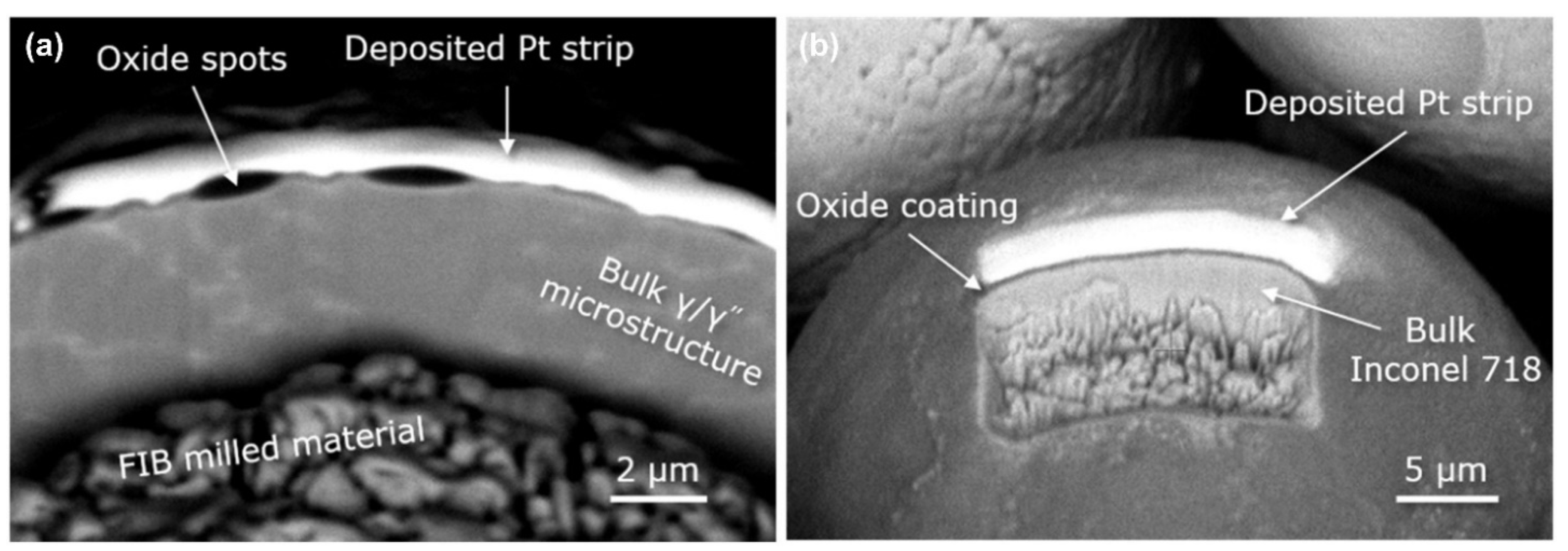
| Appearance and Composition | Inconel 718 | (i) Particles similar to virgin gas-atomized particles; (ii) Particles with morphology different to gas-atomized; (iii) Larger singular particles with different morphologies; (iv) Particles with oxide spots; (v) Particles covered with oxide; (vi) Small particles; (vii) agglomerates | Gasper et al. (2018) [66] |
| Al-Si10-Mg | Hollow droplets, semi-hollow droplets, solid droplets | Yang et al. (2020) [67] | |
| Generation Mechanism | Materials | References |
|---|---|---|
| Surface tension | Ti-6Al-4V, TiC | Dai et al. (2020) [74] |
| Al-Cr-Zr-Mn, Al-Cr-Sc-Zr & Al-Mg-Sc-Mn-Zr | Bärtl et al. (2022) [75] | |
| Vapor recoil pressure | 316L | Khairallah et al. (2016) [68] |
| Inconel 718 | Yin et al. (2019) [41] | |
| Yin et al. (2020) [34] | ||
| Explosion | Ti-6Al-4V | Zhao et al. (2019) [71] |
| Cu-10Zn | Yin et al. (2021) [72] | |
| Laser energy uneven deposition | 316, Ti-6Al-4V | Khairallah et al. (2020) [69] |
| Movement process of melt and powder | 316L | Wang et al.(2021) [48] |
| Generation Mechanism | Material | References |
|---|---|---|
| Metal vapor-induced entrainment | 316L, Ti-6Al-4V | Ly et al. (2017) [64] |
| 316L, 4047 aluminum–silicon | Gunenthiram et al. (2018) [78] | |
| 316L | Chen et al. (2020) [77] | |
| GH4169 | Yin et al. (2022) [61] | |
| Metal vapor recoil pressure | 304 | Zheng et al. (2018) [51] |
| Dominant Mechanism | Material | Research Content | References |
|---|---|---|---|
| Vapor-induced recoil pressure | Al-Si10-Mg | Number of laser beams ↑, Recoil pressure ↑, Number of spatters ↑. | Andani et al. (2017) [79] |
| Vapor-entrainment effect | Inconel 718 | Spatter growth rate (rs) in vapor entrainment dominant stages is one order of magnitude higher than that in unstable melt pool dominant stage | Yin et al. (2021) [80] |
| Material | Powder Parameters | Re-Cycle Times | References |
|---|---|---|---|
| 316L | 20~45µm | 10–15 | Gorji et al. (2019) [99] Delacroix et al. (2022) [94] |
| Ti-6Al-4V | <63 µm | 21–31 | Tang et al. (2015) [100] Quintana et al. (2018) [95] |
| Al-Si10-Mg | 20~63 µm | 6–30 | Cordova et al. (2019) [96] Mohd et al. (2020) [101] |
| 17-4 PH | 15~45 µm | 5–11 | Nezhadfar et al. (2018) [97] Jacob et al. (2017) [102] |
| Hastelloy X | 20~60 µm | 6 | He et al. (2022) [98] |
| Disadvantage | Material | References | |
|---|---|---|---|
| Printing processing | Laser energy loss | 316L | Liu et al. (2015) [62] |
| Ti-6Al-4V | Pal et al. (2020) [106] | ||
| Abrasion of scraper | CoCr | Wang et al. [63] | |
| Hastelloy X | Schwerz et al. [82] | ||
| Structure and mechanical property (current L-PBF manufacturing) | Spatter oxidation (oxygen content of part increases due to redeposited spatters) | 316L | Hatami et al. (2021) [107] |
| Al-Si10-Mg | Lutter et al. (2018) [108] | ||
| Lack of fusion | CoCrMo | Darvish et al. (2016) [109] | |
| Al-Si10-Mg; Ti-6Al-4V | Young et al. (2020) [56] | ||
| Ti-6Al-4V | Pal et al. (2020) [106] | ||
| 316L | Obeidi et al. (2020) [110] | ||
| Inconel 718 | Ladewig et al. (2016) [87] | ||
| CoCr | Wang et al. (2017) [63] | ||
| Increase in surface roughness | 17-4 PH | Ali et al. (2019) [111] | |
| Hastelloy-X | Esmaeilizadeh et al. (2019) [112] | ||
| Powder recycling (subsequent L-PBF manufacturing) | Porosity increase | Ti-6Al-4V | Strondl et al. (2015) [113] |
| Mixing of spatter particles | Al-Si10-Mg | Lutter et al. (2018) [108] | |
| 304 L | Obeidi et al. (2020) [110] | ||
| High oxygen content (oxidized spatter in recycled powder increases) | Hastelloy X | Esmaeilizadeh et al. (2019) [112] | |
| 316L | Lu et al. (2022) [114] | ||
| Process Parameters | Spatter Countermeasures | Materials | References |
|---|---|---|---|
| Laser VED | Decrease laser power | 316L, TC4 | Liu et al. (2015) [62] Shi et al. (2021) [115] Luo et al. (2021) [42] Chen et al. (2022) [46] |
| Increase laser scanning velocity | Al-Si10-Mg | Andani et al. (2018) [52] | |
| Increase laser spot | 316L, 4047 Al-Si alloy; Inconel 625; Ti-6Al-4V | Gunenthiram et al. (2018) [78] Sow et al. (2020) [116] Young et al. (2022) [117] | |
| Reduce layer thickness | 316L | Zhang et al. (2022) [38] | |
| Laser beam modes | Bessel beams | 316L | Nguyen et al. (2021) [118] |
| Flat-top beam | Co-Cr | Okunkova et al. (2014) [119] | |
| Printing Strategy | Pre-sintering | 316L, Al-Si10-Mg, Ti-6Al-4V | Simonelli et al. (2015) [103] |
| Ti-6Al-4V, 316L | Khairallah et al. (2020) [69] | ||
| Scan in the opposite direction to the gas flow | Al-Si10-Mg | Andani et al. (2017) [79] Anwar et al. (2018) [85] Anwar et al. (2019) [120] | |
| Ambient pressure | Increasing the ambient pressure | 316L | Bidare et al. (2018) [121] |
| Pure (CP) titanium grade 2, Maraging steel 1.2709 | Kaserer et al. (2020) [122] | ||
| 316L | Guo et al. (2018) [36] Li et al. (2021) [123] | ||
| Protective Gas | Reducing the oxygen content of atmosphere | 316L | Wu et al. (2016) [124] |
| Increase gas flow velocity (without blowing away the powder bed) | Inconel 718 | Ladewig et al. (2016) [87] | |
| Adding helium to protective gas | Ti-6Al-4V | Pauzon et al. (2021) [125] | |
| Printing in the central area of the powder bed | Ti-6Al-4V | Wang et al. (2021) [126] |
| Materials | Spatter Countermeasures | References | |
|---|---|---|---|
| L-PBF equipment | 316L, Aluminum | Uniformity of flow field | Philo et al. (2018) [135] Xiao et al. (2021) [136] |
| 316L | Prevent powder from blowing away | Zhang et al. (2020) [137] | |
| 316L | High gravity powder bed | Koike et al. (2021) [138,139] | |
| Powder materials | 316L, 13-93 bioactive glass | Increasing the viscosity of melt | Leung et al. (2018) [140] |
| AISI 4130; 316L | Reducing the oxygen content of powder | Heiden et al. (2019) [141] Fedina et al. (2020) [142] Fedina et al. (2021) [143] |
Publisher’s Note: MDPI stays neutral with regard to jurisdictional claims in published maps and institutional affiliations. |
© 2022 by the authors. Licensee MDPI, Basel, Switzerland. This article is an open access article distributed under the terms and conditions of the Creative Commons Attribution (CC BY) license (https://creativecommons.org/licenses/by/4.0/).
Share and Cite
Li, Z.; Li, H.; Yin, J.; Li, Y.; Nie, Z.; Li, X.; You, D.; Guan, K.; Duan, W.; Cao, L.; et al. A Review of Spatter in Laser Powder Bed Fusion Additive Manufacturing: In Situ Detection, Generation, Effects, and Countermeasures. Micromachines 2022, 13, 1366. https://doi.org/10.3390/mi13081366
Li Z, Li H, Yin J, Li Y, Nie Z, Li X, You D, Guan K, Duan W, Cao L, et al. A Review of Spatter in Laser Powder Bed Fusion Additive Manufacturing: In Situ Detection, Generation, Effects, and Countermeasures. Micromachines. 2022; 13(8):1366. https://doi.org/10.3390/mi13081366
Chicago/Turabian StyleLi, Zheng, Hao Li, Jie Yin, Yan Li, Zhenguo Nie, Xiangyou Li, Deyong You, Kai Guan, Wei Duan, Longchao Cao, and et al. 2022. "A Review of Spatter in Laser Powder Bed Fusion Additive Manufacturing: In Situ Detection, Generation, Effects, and Countermeasures" Micromachines 13, no. 8: 1366. https://doi.org/10.3390/mi13081366