
A Highly Accurate Method for Deformation Reconstruction of Smart Deformable Structures Based on Flexible Strain Sensors

Abstract
:1. Introduction
2. The Mechanical Model of the FFN Plate with Multiple Pivots
3. The Derivation and Modification of the Reconstruction Algorithm
3.1. Relationship of the Strain and Moment
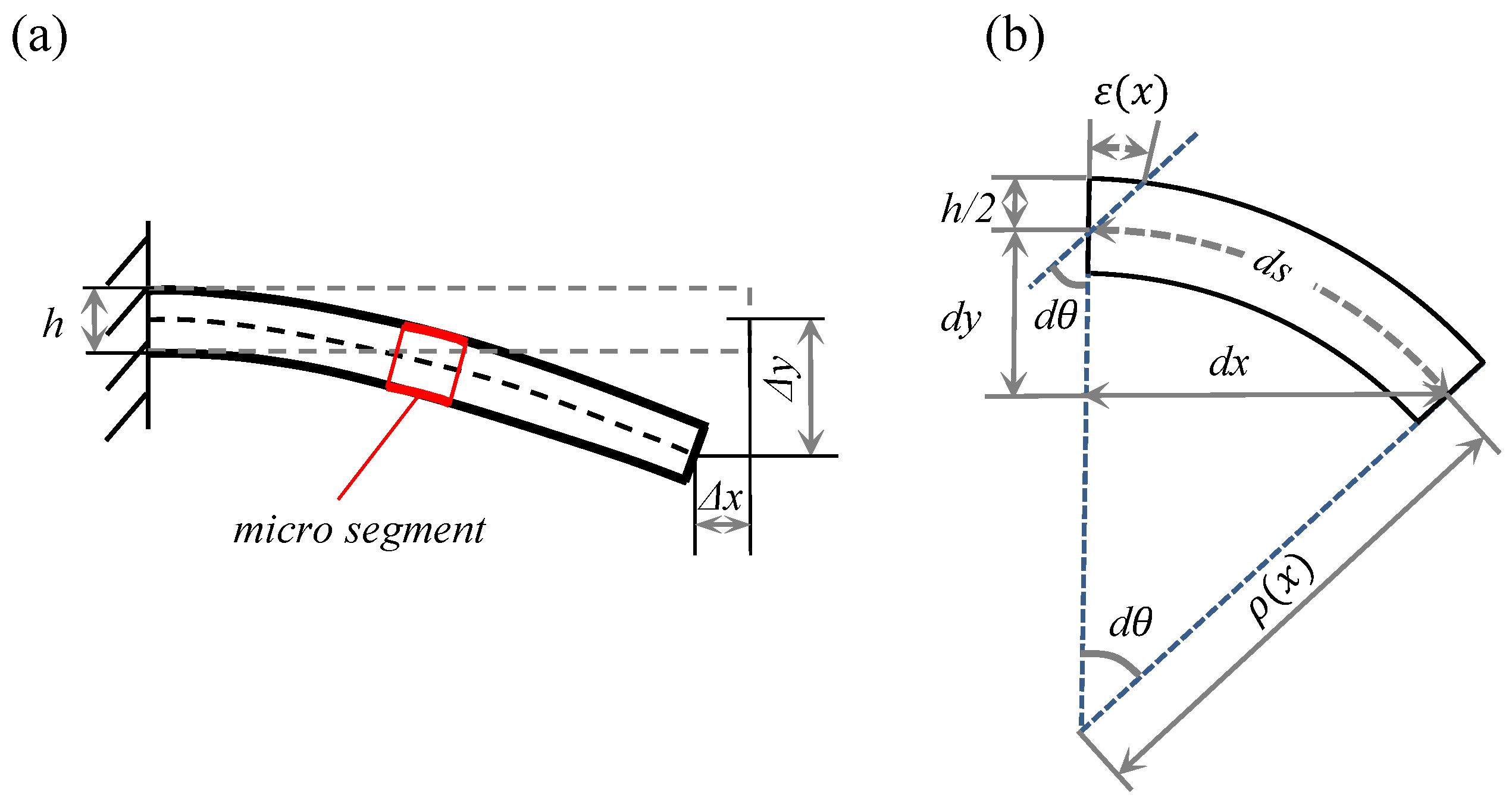
3.2. Derivation of the Deformation with Large Deflection
3.3. Stiffness Revising Based on Shell Bending Theory
4. Evaluation of the Reconstruction Algorithm
4.1. Comparison with the Ko Theory
4.2. Evaluation of the Modified Method
5. Results and Discussion
6. Experimental
7. Conclusions
Author Contributions
Funding
Institutional Review Board Statement
Informed Consent Statement
Data Availability Statement
Acknowledgments
Conflicts of Interest
References
- Wen, J.; Li, Q.; Zhao, L.; Huang, Q.; Lu, Z. Aerodynamic Characteristics of Express Freight Train on Bridges Based on Wind Tunnel Tests. Int. J. Struct. Stab. Dyn. 2022, 23, 2241005. [Google Scholar] [CrossRef]
- Auteri, F.; Savino, A.; Zanotti, A.; Gibertini, G.; Zagaglia, D.; Tekap, Y.B.; Braza, M. Experimental evaluation of the aerodynamic performance of a large-scale high-lift morphing wing. Aerosp. Sci. Technol. 2022, 124, 107515. [Google Scholar] [CrossRef]
- Paryz, R. Recent Developments at the NASA Langley Research Center National Transonic Facility. In Proceedings of the 49th AIAA Aerospace Sciences Meeting including the New Horizons Forum and Aerospace Exposition, Orlando, FL, USA, 4–7 January 2011; American Institute of Aeronautics and Astronautics: Reston, VA, USA, 2011. [Google Scholar] [CrossRef] [Green Version]
- Bordogna, G.; Muggiasca, S.; Giappino, S.; Belloli, M.; Keuning, J.A.; Huijsmans, R.H.M.; van‘t Veer, A.P. Wind-Tunnel Experiments on a Large-Scale Flettner Rotor. In Lecture Notes in Civil Engineering; Springer International Publishing: Berlin/Heidelberg, Germany, 2019; pp. 110–123. [Google Scholar] [CrossRef]
- Chen, P.; Wu, F.; Xu, J.; Feng, X.; Yang, Q. Design and implementation of rigid-flexible coupling for a half-flexible single jack nozzle. Chin. J. Aeronaut. 2016, 29, 1477–1483. [Google Scholar] [CrossRef] [Green Version]
- Lv, Z.; Xu, J.; Wu, F.; Chen, P.; Wang, J. Design of a variable Mach number wind tunnel nozzle operated by a single jack. Aerosp. Sci. Technol. 2018, 77, 299–305. [Google Scholar] [CrossRef]
- Laijun, Y.; Long, Z.; Peiyuan, W.; Yungang, W.; Kewei, Y.; Jun, Z. Applications of laser tracking measurement system in wind tunnels. In Proceedings of the 2017 13th IEEE International Conference on Electronic Measurement Instruments, Yangzhou, China, 20–22 October 2017. [Google Scholar] [CrossRef]
- Ilić, B.; Milosavljević, M. FPGA-based embedded system for wind tunnel variable-geometry nozzle positioning. Sci. Tech. Rev. 2019, 69, 3–9. [Google Scholar] [CrossRef]
- Pederson, K.; Suarez, V. Utilizing Modal Testing for Monitoring the Structural Health of Wind Tunnel Facility Hardware. In Nonlinear Structures & Systems; Kerschen, G., Brake, M.R., Renson, L., Eds.; Conference Proceedings of the Society for Experimental Mechanics Series; Springer International Publishing: Cham, Switzerland, 2021; Volume 1, pp. 279–286. [Google Scholar] [CrossRef]
- Liu, Z.; Mrad, N. Validation of Strain Gauges for Structural Health Monitoring with Bayesian Belief Networks. IEEE Sens. J. 2013, 13, 400–407. [Google Scholar] [CrossRef]
- Dos Reis, J.; Oliveira Costa, C.; Sá da Costa, J. Strain gauges debonding fault detection for structural health monitoring. Struct. Control. Health Monit. 2018, 25, e2264. [Google Scholar] [CrossRef]
- García, I.; Zubia, J.; Durana, G.; Aldabaldetreku, G.; Illarramendi, M.; Villatoro, J. Optical Fiber Sensors for Aircraft Structural Health Monitoring. Sensors 2015, 15, 15494–15519. [Google Scholar] [CrossRef] [PubMed] [Green Version]
- Bado, M.F.; Casas, J.R. A Review of Recent Distributed Optical Fiber Sensors Applications for Civil Engineering Structural Health Monitoring. Sensors 2021, 21, 1818. [Google Scholar] [CrossRef] [PubMed]
- Nie, X.T.; Guo, L.D.; Liu, B.L. Dynamics simulation and analysis of flexible nozzle in wind tunnel based on ADAMS. J. Exp. Fluid Mech. 2011, 2, 73–76. [Google Scholar]
- Chuan, G.; Wei, R.; Xuhui, H.; Jiang, J. Contour control of the full flexible nozzle in the wind tunnel based on virtual shaft. In Proceedings of the The 27th Chinese Control and Decision Conference (2015 CCDC), Qingdao, China, 23–25 May 2015. [Google Scholar] [CrossRef]
- Ko, W.; Richards, W.L.; Fleischer, V. Applications of KO Displacement Theory to the Deformed Shape Predictions of the Doubly-Tapered Ikhana Wing; NASA Dryden Flight Research Center: Edwards, CA, USA, 2009.
- Derkevorkian, A.; Masri, S.F.; Alvarenga, J.; Boussalis, H.; Bakalyar, J.; Richards, W.L. Strain-Based Deformation Shape-Estimation Algorithm for Control and Monitoring Applications. AIAA J. 2013, 51, 2231–2240. [Google Scholar] [CrossRef]
- Ding, G.; Yue, S.; Zhang, S.; Song, W. Strain—Deformation reconstruction of CFRP laminates based on Ko displacement theory. Nondestruct. Test. Eval. 2020, 36, 145–157. [Google Scholar] [CrossRef]
- Liu, M.; Wang, L.; Yun, K.; Zhu, Z. Study on the deformation measurement and reconstruction of heavy-duty machine column based on FBG sensor. In Proceedings of the 2016 IEEE International Conference on Mechatronics and Automation, Harbin, China, 7–10 August 2016. [Google Scholar] [CrossRef]
- Tessler, A.; Spangler, J.L. A least-squares variational method for full-field reconstruction of elastic deformations in shear-deformable plates and shells. Comput. Methods Appl. Mech. Eng. 2005, 194, 327–339. [Google Scholar] [CrossRef]
- Song, X.; Zhai, H.; Liang, D. Dynamic Load Identification and Displacement Prediction Based on FBG for a Cantilever Beam. J. Vib. Eng. Technol. 2019, 7, 131–137. [Google Scholar] [CrossRef]
- You, R.; Ren, L.; Yuan, C.; Song, G. Two-Dimensional Deformation Estimation of Beam-Like Structures Using Inverse Finite-Element Method: Theoretical Study and Experimental Validation. J. Eng. Mech. 2021, 147, 04021019. [Google Scholar] [CrossRef]
- Chen, B.; Liu, Y.; Wang, G.; Cheng, X.; Liu, G.; Qiu, J.; Lv, K. Low-Cost Flexible Strain Sensor Based on Thick CVD Graphene. Nano 2018, 13, 1850126. [Google Scholar] [CrossRef]
- Wang, G.; Yang, P.; Chen, B.; Liu, G.; Qiu, J. A novel combination of graphene and silver nanowires for entirely stretchable and ultrasensitive strain sensors: Sandwich-based sensing films. Nanotechnology 2020, 31, 135501. [Google Scholar] [CrossRef] [PubMed]
- Wang, G.; Liu, Y.; Xu, F.; Liu, G.; Qiu, J. Design and optimization of isotropic stretchable strain sensors for multidirectional monitoring. Smart Mater. Struct. 2022, 31, 015009. [Google Scholar] [CrossRef]


| n | b (mm) | h (mm) | (mm) | (mm) | E (MPa) |
|---|---|---|---|---|---|
| 2 | 5 | 5 | 175 | 175 |
| Condition | (N) | (N) | (N·mm) |
|---|---|---|---|
| 1 | 5 | 10 | 20 |
| 2 | −15 | 20 | 20 |
| 3 | 5 | 10 | 2000 |
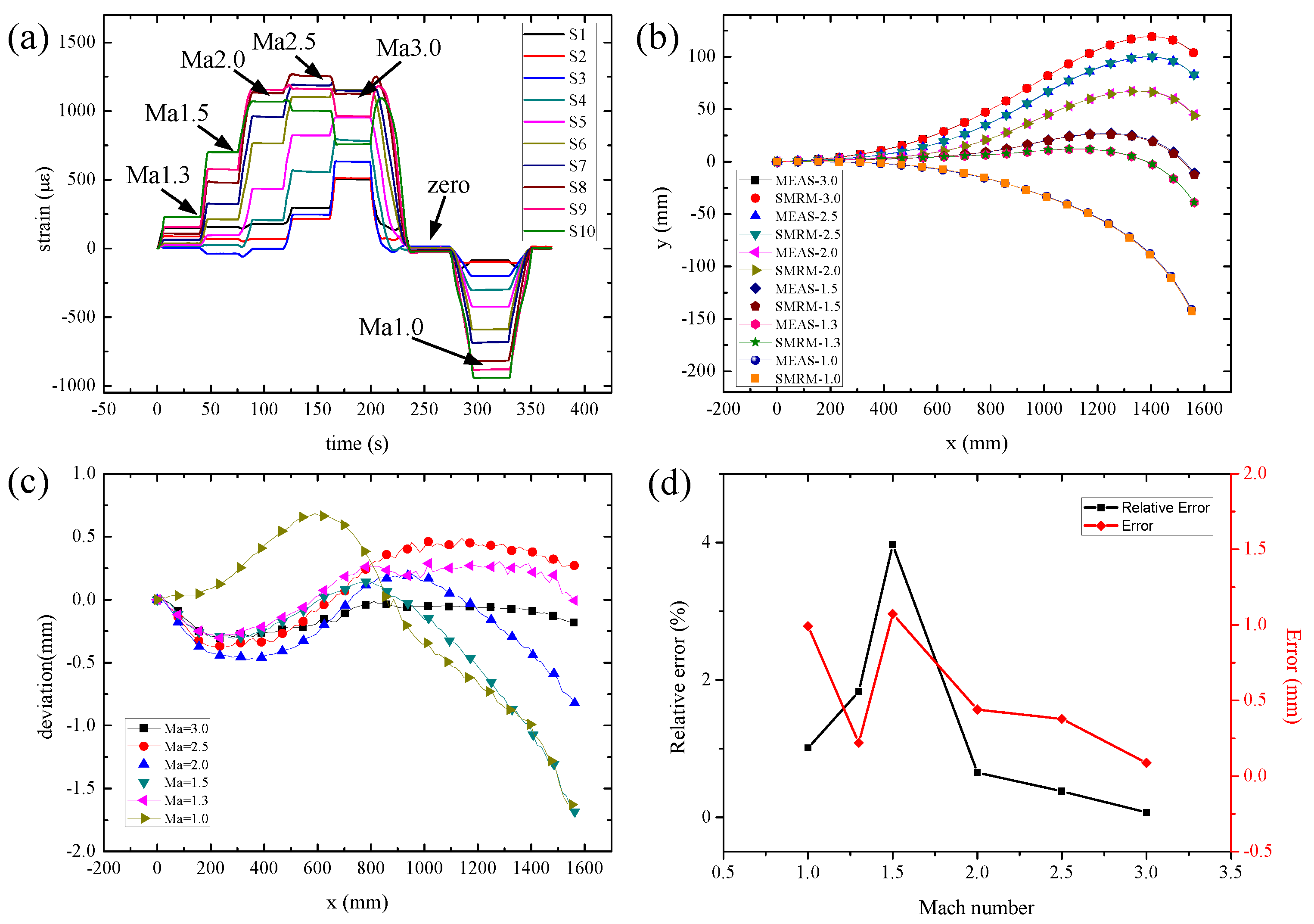
| Ma | Max. Displacement (mm) | Absolute Error | Relative Error |
|---|---|---|---|
| 1.0 | −98 | 0.99 | 1.01% |
| 1.3 | 12 | 0.22 | 1.83% |
| 1.5 | 27.03 | 1.07 | 3.97% |
| 2.0 | 67.51 | 0.44 | 0.65% |
| 2.5 | 99.98 | 0.38 | 0.38% |
| 3.0 | 119.41 | 0.09 | 0.07% |
Publisher’s Note: MDPI stays neutral with regard to jurisdictional claims in published maps and institutional affiliations. |
© 2022 by the authors. Licensee MDPI, Basel, Switzerland. This article is an open access article distributed under the terms and conditions of the Creative Commons Attribution (CC BY) license (https://creativecommons.org/licenses/by/4.0/).
Share and Cite
Yu, C.; Gao, X.; Liao, W.; Zhang, Z.; Wang, G. A Highly Accurate Method for Deformation Reconstruction of Smart Deformable Structures Based on Flexible Strain Sensors. Micromachines 2022, 13, 910. https://doi.org/10.3390/mi13060910
Yu C, Gao X, Liao W, Zhang Z, Wang G. A Highly Accurate Method for Deformation Reconstruction of Smart Deformable Structures Based on Flexible Strain Sensors. Micromachines. 2022; 13(6):910. https://doi.org/10.3390/mi13060910
Chicago/Turabian StyleYu, Chengguo, Xinyu Gao, Wenlin Liao, Zhili Zhang, and Guishan Wang. 2022. "A Highly Accurate Method for Deformation Reconstruction of Smart Deformable Structures Based on Flexible Strain Sensors" Micromachines 13, no. 6: 910. https://doi.org/10.3390/mi13060910