
Simulating the Residual Layer Thickness in Roll-to-Plate Nanoimprinting with Tensioned Webs


Abstract
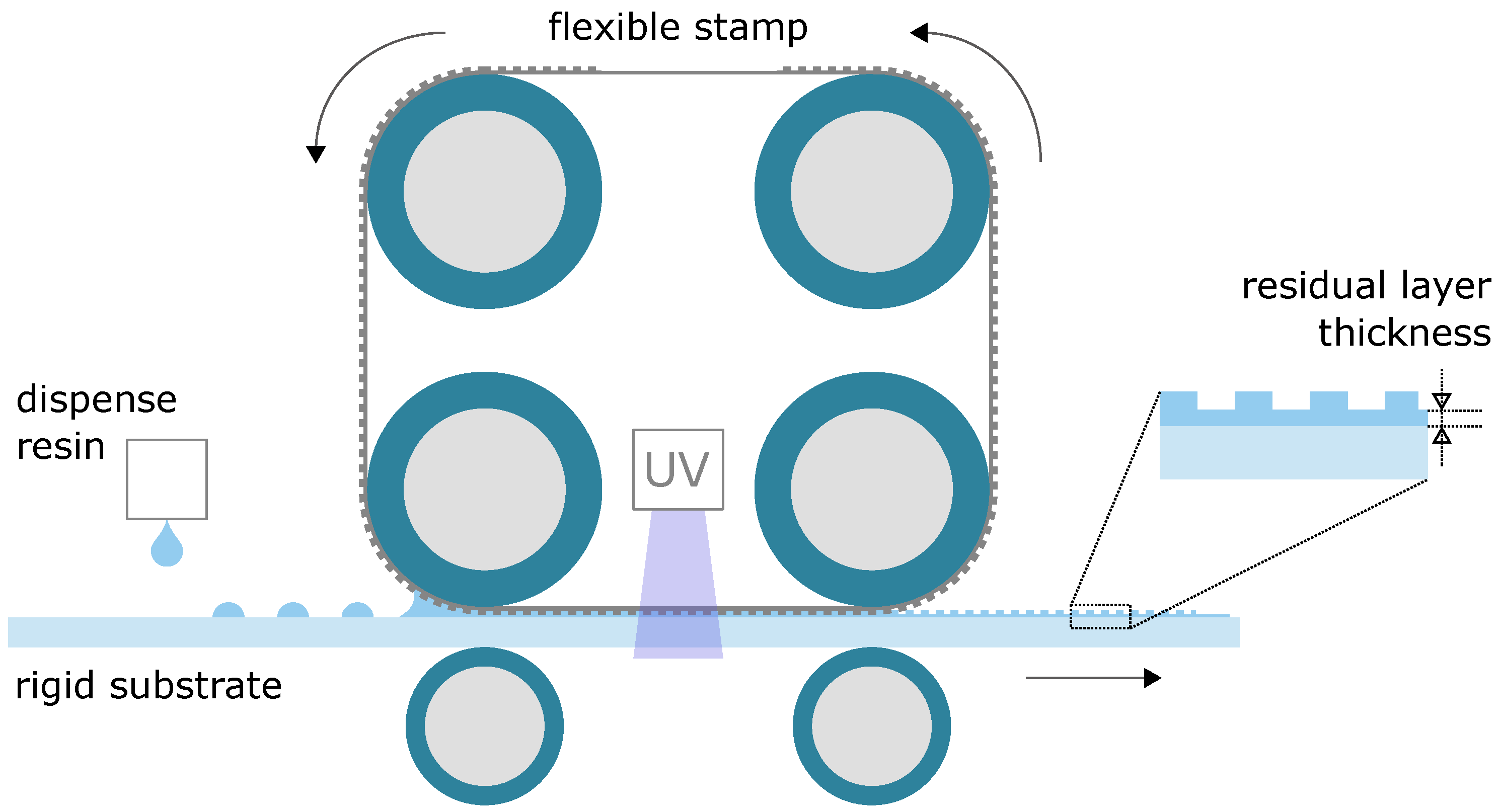
:1. Introduction
2. Methods
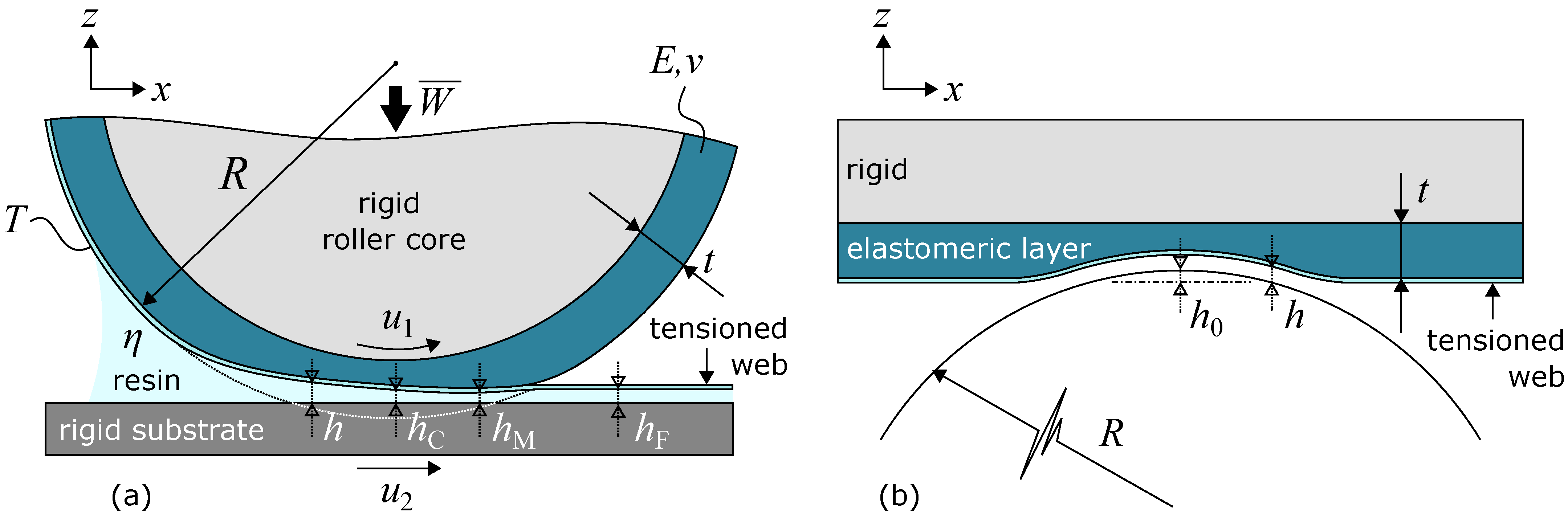
2.1. Model Development
2.1.1. Elastic Deformation
2.1.2. Hydrodynamic Lubrication
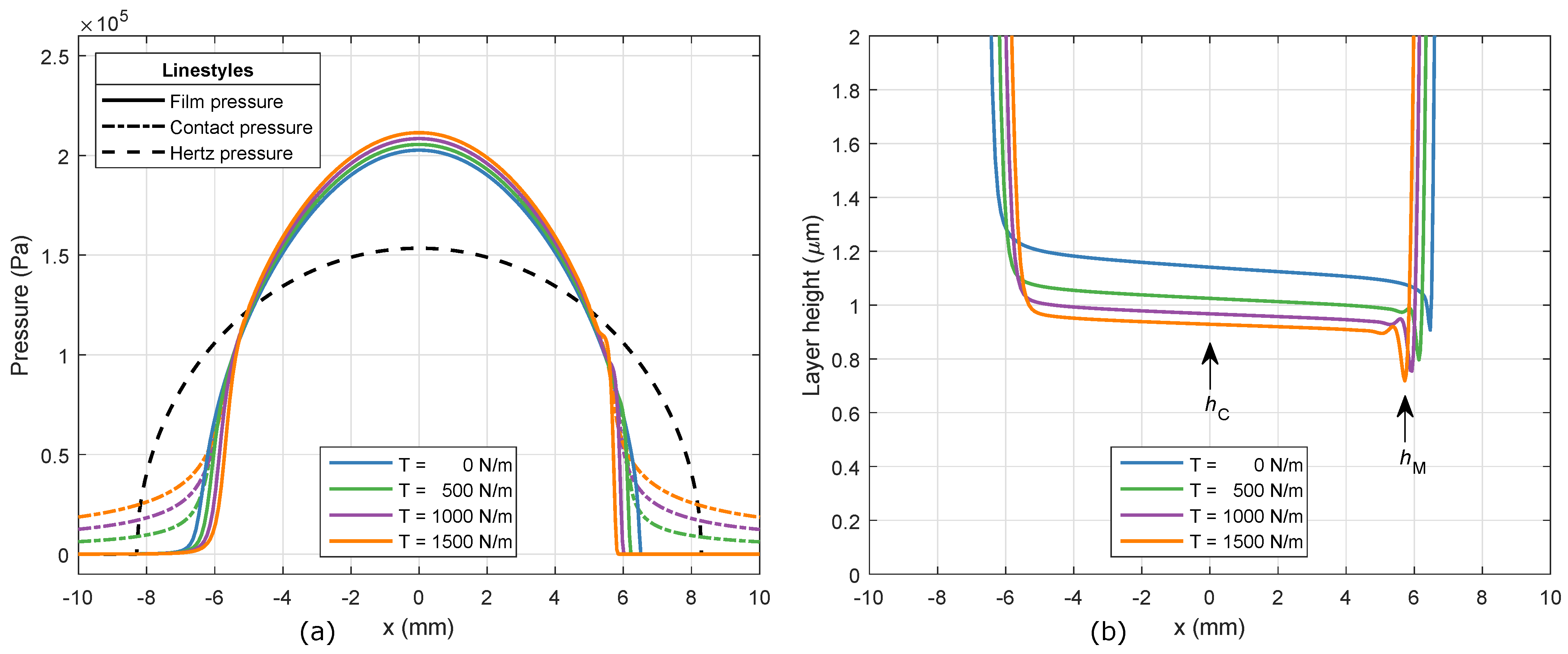
2.1.3. Web Tension
2.1.4. Load Balance
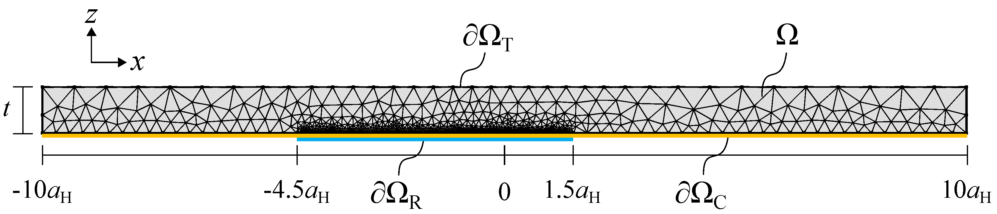
2.1.5. Numerical Implementation
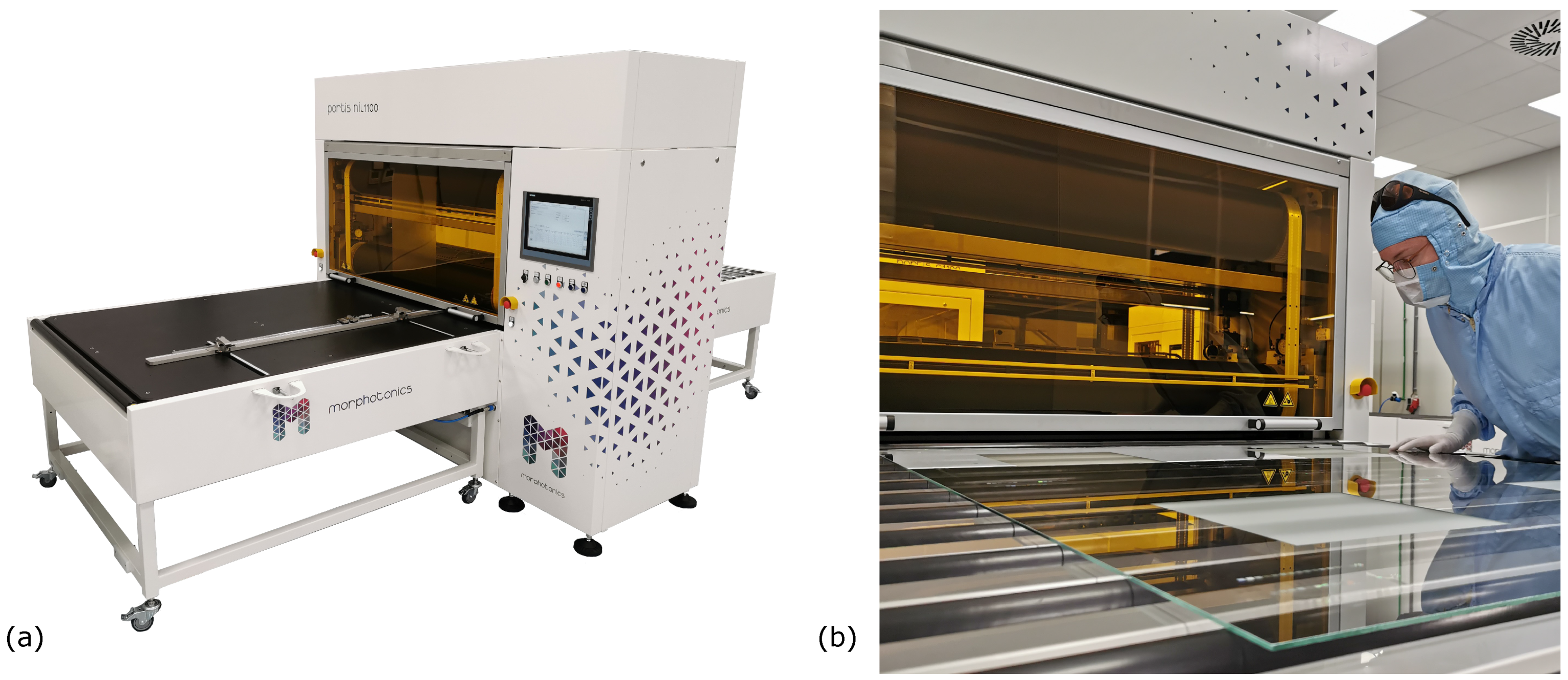
2.2. Experimental
3. Results
3.1. Model
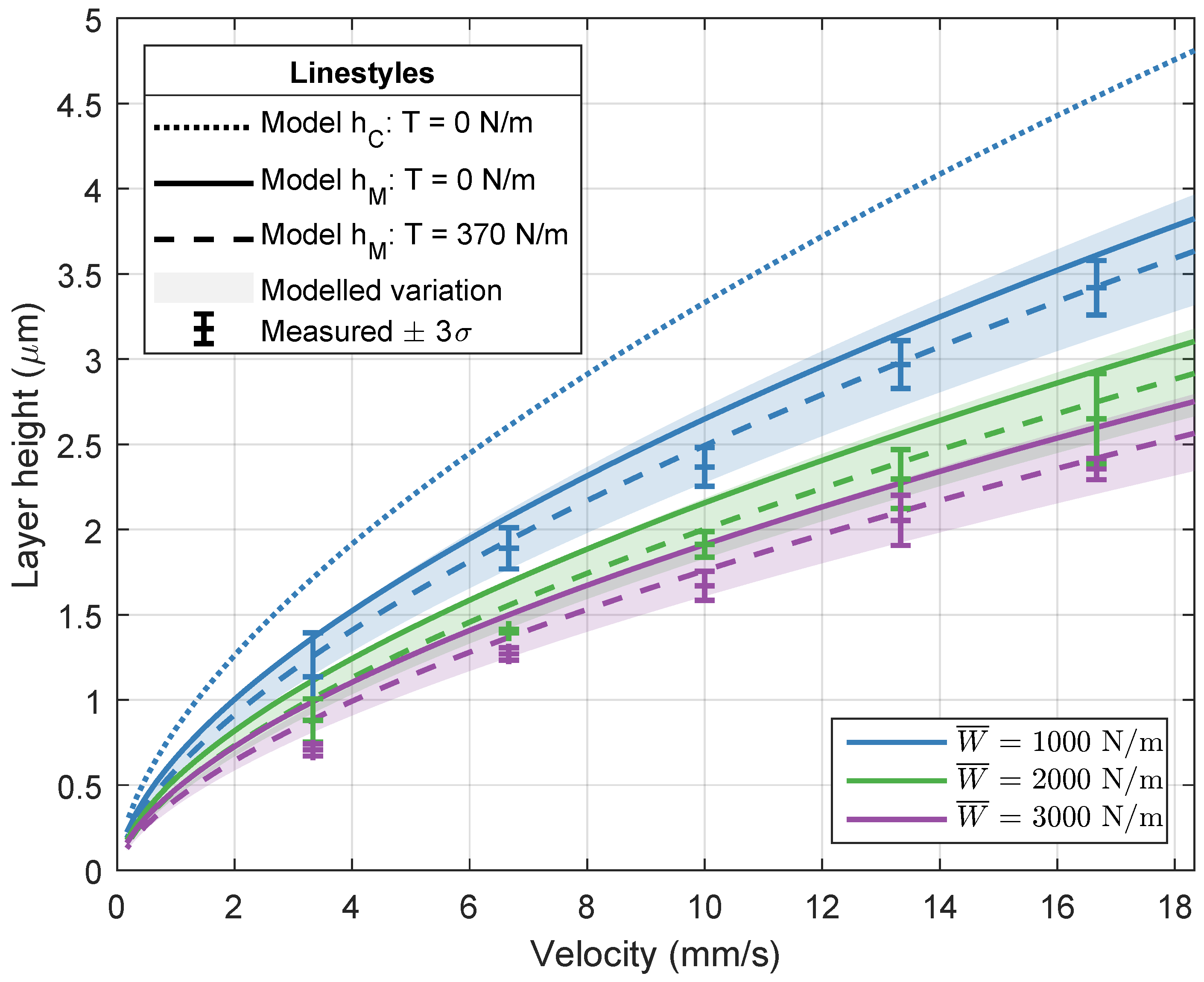
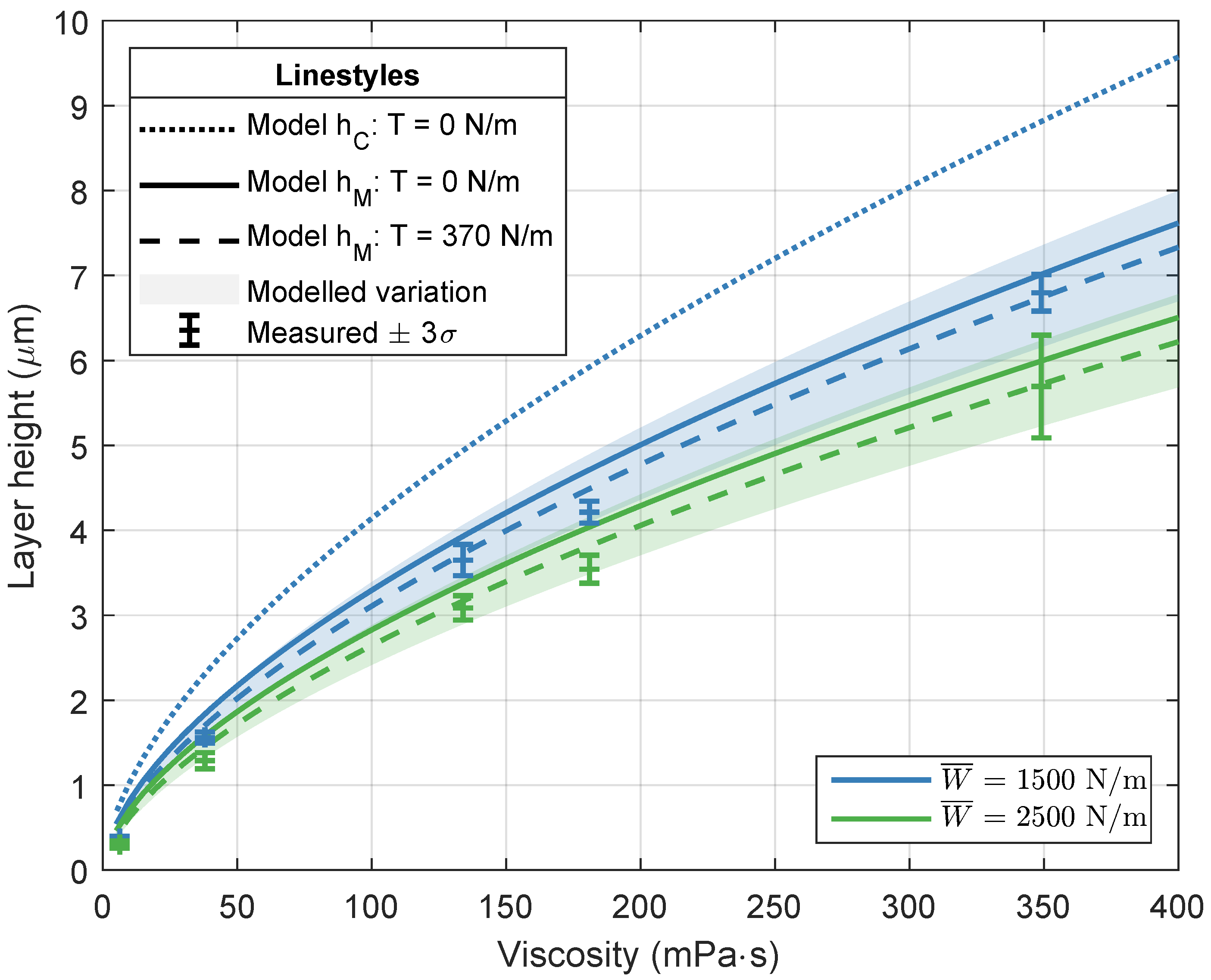
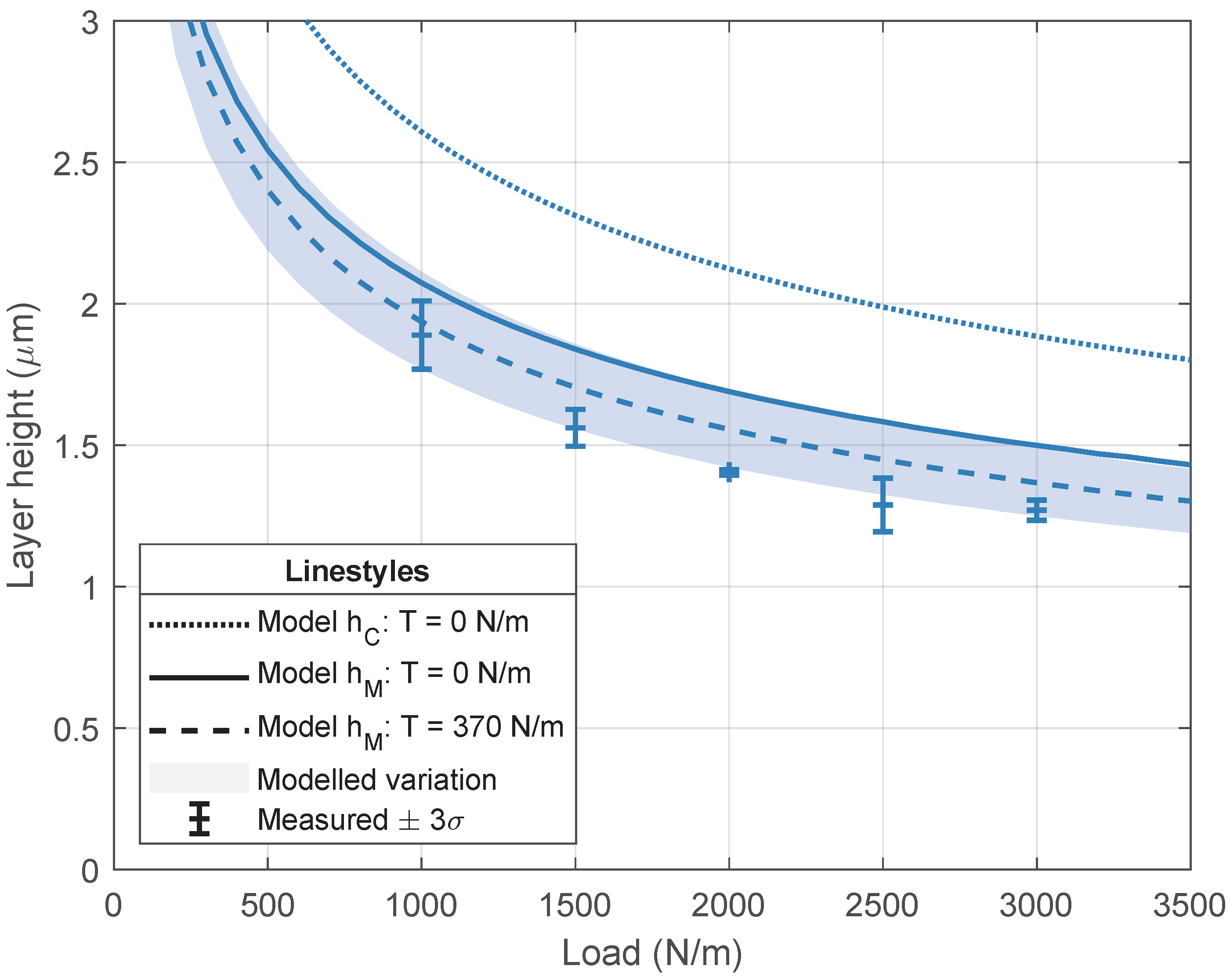
3.2. Experimental Validation
4. Discussion
5. Conclusions
Supplementary Materials
Author Contributions
Funding
Institutional Review Board Statement
Informed Consent Statement
Data Availability Statement
Acknowledgments
Conflicts of Interest
Nomenclature
| Abbreviations | |
| EHL | Elastohydrodynamic Lubrication |
| FEM | Finite Element Method |
| NIL | Nanoimprint Lithography |
| RLT | Residual Layer Thickness |
| UV | Ultraviolet |
| Symbols | |
| aH | Hertz contact half-width (m) |
| E | Elastic modulus (Pa) |
| E′ | Effective elastic modulus (Pa) |
| f | Liquid volume fraction (-) |
| h | Film/layer height (m) |
| h0 | Gap between roller and substrate at x = 0 (m) |
| hC | Central layer height (m) |
| hF | Final layer height (m) |
| hM | Minimum layer height (m) |
| p | Hydrodynamic film pressure (Reynolds) (Pa) |
| pC | Tensioned web contact pressure (Pa) |
| pH | Hertz contact pressure (Pa) |
| pn | Normal pressure on the tensioned web (Pa) |
| R | Roller radius (m) |
| T | Web tension (N m−1) |
| t | Elastomeric layer thickness (m) |
| u | Elastic deformation in x (m) |
| u1 | Roller surface imprint velocity (m s−1) |
| u2 | Substrate surface imprint velocity (m s−1) |
| w | Elastic deformation in z (m) |
| Effective imprint load per unit length (N m−1) | |
| x | Space coordinate in horizontal direction (m) |
| z | Space coordinate in vertical direction (m) |
| zroller | Roller height profile (m) |
| η | Resin dynamic viscosity (Pa s) |
| θ | Cavity fraction (1 − f ) (-) |
| Curvature of the tensioned web (m−1) | |
| λ | Lamé’s first parameter (Pa) |
| μ | Lamé’s second parameter (Pa) |
| v | Poisson ratio (-) |
| σn | Normal component of the stress tensor (Pa) |
| σt | Tangential component of the stress tensor (Pa) |
References
- Schift, H.; Kristensen, A. Nanoimprint Lithography. In Springer Handbook of Nanotechnology; Bhushan, B., Ed.; Springer Handbooks; Springer: Berlin, Heidelberg, 2007; pp. 239–278. [Google Scholar] [CrossRef]
- Chou, S.; Krauss, P.; Renstrom, P. Imprint of Sub-25 Nm Vias and Trenches in Polymers. Appl. Phys. Lett. 1995, 67, 3114–3116. [Google Scholar] [CrossRef] [Green Version]
- Haisma, J.; Verheijen, M.; van den Heuvel, K.; van den Berg, J. Mold-assisted Nanolithography: A Process for Reliable Pattern Replication. J. Vac. Sci. Technol. B Microelectron. Nanometer Struct. Process. Meas. Phenom. 1996, 14, 4124–4128. [Google Scholar] [CrossRef]
- Lan, H. Large-Area Nanoimprint Lithography and Applications. In Micro/Nanolithography—A Heuristic Aspect on the Enduring Technology; IntechOpen: London, UK, 2018. [Google Scholar]
- Ter Meulen, J.M.; Veldhuizen, L.; Kommeren, A.; Willems, A.G.; Dielen, M.; Driessen, E.; Neelen, R.A.; Ercan, E.; Tam, K.K.G.; Titulaer, B.J. 33-6: Roll-To-Plate Nano-Imprint Lithography for High-Volume Production of AR Glasses: Equipment, Materials, and Processes. SID Symp. Dig. Tech. Pap. 2021, 52, 447–449. [Google Scholar] [CrossRef]
- Van Erven, A.; Steltenpool, M.; Bos, M.; Rutten, J.; van der Hofstad, G.; Muller, J.; de Groot, H.; de Ruijter, J.; Tavakoliyaraki, A.; Titulaer, B.; et al. Gen5 Production Tool for Light Management Textures. In Proceedings of the 2012 38th IEEE Photovoltaic Specialists Conference, Austin, TX, USA, 3–8 June 2012. [Google Scholar] [CrossRef]
- Atthi, N.; Dielen, M.; Sripumkhai, W.; Pattamang, P.; Meananeatra, R.; Saengdee, P.; Thongsook, O.; Ranron, N.; Pankong, K.; Uahchinkul, W.; et al. Fabrication of High Aspect Ratio Micro-Structures with Superhydrophobic and Oleophobic Properties by Using Large-Area Roll-to-Plate Nanoimprint Lithography. Nanomaterials 2021, 11, 339. [Google Scholar] [CrossRef]
- Kooy, N.; Mohamed, K.; Pin, L.T.; Guan, O.S. A Review of Roll-to-Roll Nanoimprint Lithography. Nanoscale Res. Lett. 2014, 9, 320. [Google Scholar] [CrossRef] [Green Version]
- Tan, H.; Gilbertson, A.; Chou, S.Y. Roller Nanoimprint Lithography. J. Vac. Sci. Technol. B Microelectron. Nanometer Struct. 1998, 16, 3926–3928. [Google Scholar] [CrossRef] [Green Version]
- Ahn, S.; Cha, J.; Myung, H.; Kim, S.M.; Kang, S. Continuous Ultraviolet Roll Nanoimprinting Process for Replicating Large-Scale Nano- and Micropatterns. Appl. Phys. Lett. 2006, 89, 213101. [Google Scholar] [CrossRef]
- Dumond, J.J.; Yee Low, H. Recent Developments and Design Challenges in Continuous Roller Micro- and Nanoimprinting. J. Vac. Sci. Technol. B 2012, 30, 010801. [Google Scholar] [CrossRef]
- Yi, P.; Wu, H.; Zhang, C.; Peng, L.; Lai, X. Roll-to-Roll UV Imprinting Lithography for Micro/Nanostructures. J. Vac. Sci. Technol. B 2015, 33, 060801. [Google Scholar] [CrossRef]
- Smith, B.W.; Suzuki, K. (Eds.) Microlithography: Science and Technology, 3rd ed.; CRC Press: Boca Raton, FL, USA, 2020. [Google Scholar]
- Gomez-Constante, J.P.; Pagilla, P.R.; Rajagopal, K.R. A Thermomechanical Description of the Mold Filling Process in Roll-to-Roll Nanoimprinting Lithography. Appl. Eng. Sci. 2020, 1, 100001. [Google Scholar] [CrossRef]
- Cui, Y.; Wang, X.; Zhang, C.; Wang, J.; Shi, Z. Numerical Investigation for the Resin Filling Behavior during Ultraviolet Nanoimprint Lithography of Subwavelength Moth-Eye Nanostructure. Coatings 2021, 11, 799. [Google Scholar] [CrossRef]
- Götz, J.; Alvarez Rueda, A.; Ruttloff, S.; Kuna, L.; Belegratis, M.; Palfinger, U.; Nees, D.; Hartmann, P.; Stadlober, B. Finite Element Simulations of Filling and Demolding in Roll-to-Roll UV Nanoimprinting of Micro- and Nanopatterns. Acs Appl. Nano Mater. 2022, acsanm.1c04059. [Google Scholar] [CrossRef]
- Tahir, U.; Kim, J.I.; Javeed, S.; Khaliq, A.; Kim, J.H.; Kim, D.I.; Jeong, M.Y. Process Optimization for Manufacturing Functional Nanosurfaces by Roll-to-Roll Nanoimprint Lithography. Nanomaterials 2022, 12, 480. [Google Scholar] [CrossRef] [PubMed]
- Jain, A.; Bonnecaze, R.T. Fluid Management in Roll-to-Roll Nanoimprint Lithography. J. Appl. Phys. 2013, 113, 234511. [Google Scholar] [CrossRef]
- Gomez-Constante, J.P.; Pagilla, P.R.; Rajagopal, K.R. A Thermomechanical and Photochemical Description of the Phase Change Process in Roll-to-Roll Nanoimprinting Lithography. Int. J. Eng. Sci. 2021, 169, 103564. [Google Scholar] [CrossRef]
- Morphotonics Nanoimprint Technologies. Available online: https://www.morphotonics.com (accessed on 15 February 2022).
- Colburn, M.; Choi, B.J.; Sreenivasan, S.V.; Bonnecaze, R.T.; Willson, C.G. Ramifications of Lubrication Theory on Imprint Lithography. Microelectron. Eng. 2004, 75, 321–329. [Google Scholar] [CrossRef]
- Kehagias, N.; Reboud, V.; Sotomayor Torres, C.M.; Sirotkin, V.; Svintsov, A.; Zaitsev, S. Residual Layer Thickness in Nanoimprint: Experiments and Coarse-Grain Simulation. Microelectron. Eng. 2008, 85, 846–849. [Google Scholar] [CrossRef]
- Taylor, H.K. Defectivity Prediction for Droplet-Dispensed UV Nanoimprint Lithography, Enabled by Fast Simulation of Resin Flow at Feature, Droplet, and Template Scales. In Alternative Lithographic Technologies VIII, Proceedings of the SPIE Advanced Lithography 9777 Conference, San Jose, CA, USA, 21–25 February 2016; International Society for Optics and Photonics: Bellingham, WA, USA, 2016; Volume 97770E. [Google Scholar] [CrossRef]
- Seki, J.; Oguchi, Y.; Kiyohara, N.; Suzuki, K.; Nagane, K.; Narioka, S.; Nakayama, T.; Shiode, Y.; Aihara, S.; Asano, T. Enabling Nanoimprint Simulator for Quality Verification; Process-design Co-Optimization toward High Volume Manufacturing. In Design-Process-Technology Co-optimization for Manufacturability XIV, Proceedings of the SPIE Advanced Lithography 11328 Conference, San Jose, CA, USA, 23–27 February 2020; International Society for Optics and Photonics: Bellingham, WA, USA, 2020; Volume 113280N. [Google Scholar] [CrossRef]
- Ahn, S.H.; Guo, L.J. Large-Area Roll-to-Roll and Roll-to-Plate Nanoimprinting Lithography: A Step toward High-Throughput Application of Continuous Nanoimprinting. ACS Nano 2009, 3, 2304–2310. [Google Scholar] [CrossRef]
- Taylor, H. Fast Simulation of Pattern Formation and Process Dependencies in Roller Nanoimprint Lithography. MRS Proc. 2013, 1529, 205. [Google Scholar] [CrossRef]
- MacPhee, J.; Shieh, J.A.; Hamrock, B.J. The Application of Elastohydrodynamic Lubrication Theory to the Prediction of Conditions Existing in Lithographic Printing Press Roller Nips. In Proceedings of the Twenty-First Research Conference of the IARIGAI, Pittsburgh, PA, USA, 12–17 May 1991; pp. 242–276. [Google Scholar]
- Xue, Y.K.; Gethin, D.T.; Lim, C.H. Numerical Modelling of the Contact between Lithographic Printing Press Rollers by Soft EHL Theory. Proc. Inst. Mech. Eng. Part J J. Eng. Tribol. 1994, 208, 257–268. [Google Scholar] [CrossRef]
- Abbott, S.J.; Kapur, N.; Sleigh, P.A.; Summers, J.L.; Thompson, H.M. A Review of Deformable Roll Coating Systems. Convert. e-Print 2011, 1, 89–93. [Google Scholar]
- Grashof, B.; Delgado, A. Analysis of Influencing Parameters in Deformable Roll Coating of Counter-Rotating Rolls. J. Coat. Technol. Res. 2015, 12, 63–73. [Google Scholar] [CrossRef]
- Gupta, P.K. On the Heavily Loaded Elastohydrodynamic Contacts of Layered Solids. J. Lubr. Technol. 1976, 98, 367–372. [Google Scholar] [CrossRef]
- Hooke, C. The Elastohydrodynamic Lubrication of a Cylinder on an Elastomeric Layer. Wear 1986, 111, 83–99. [Google Scholar] [CrossRef]
- Elsharkawy, A.A.; Hamrock, B.J. Elastohydrodynamic Lubrication of Elastomeric-Coated Surfaces in Line Contact. Proc. Inst. Mech. Eng. Part J J. Eng. Tribol. 1995, 209, 119–130. [Google Scholar] [CrossRef]
- Cochrane, A.; Tjiptowidjojo, K.; Bonnecaze, R.T.; Schunk, P.R. Elastohydrodynamics of Roll-to-Roll UV-Cure Imprint Lithography. Ind. Eng. Chem. Res. 2019, 58, 17424–17432. [Google Scholar] [CrossRef]
- Habchi, W. Finite Element Modeling of Elastohydrodynamic Lubrication Problems; John Wiley & Sons: Hoboken, NJ, USA, 2018. [Google Scholar]
- Greenwood, J.A. Elastohydrodynamic Lubrication. Lubricants 2020, 8, 51. [Google Scholar] [CrossRef]
- Hamrock, B.J.; Schmid, S.R.; Jacobson, B.O. Fundamentals of Fluid Film Lubrication, 2nd ed.; Number 169 in Mechanical Engineering; Marcel Dekker: New York, NY, USA, 2004. [Google Scholar]
- Habchi, W.; Eyheramendy, D.; Vergne, P.; Morales-Espejel, G. A Full-System Approach of the Elastohydrodynamic Line/Point Contact Problem. J. Tribol. 2008, 130, 021501. [Google Scholar] [CrossRef]
- Alakhramsing, S.; van Ostayen, R.; Eling, R. Thermo-Hydrodynamic Analysis of a Plain Journal Bearing on the Basis of a New Mass Conserving Cavitation Algorithm. Lubricants 2015, 3, 256–280. [Google Scholar] [CrossRef]
- Fischer, A. A Special Newton-Type Optimization Method. Optimization 1992, 24, 269–284. [Google Scholar] [CrossRef]
- Carvalho, M.S. Elastohydrodynamics of Tensioned Web Roll Coating Process. Int. J. Numer. Methods Fluids 2003, 41, 561–576. [Google Scholar] [CrossRef]
- COMSOL Multiphysics® v. 6.0. COMSOL AB, Stockholm, Sweden. Available online: www.comsol.com/release/6.0 (accessed on 15 December 2021).
- Hooke, C.J. Elastohydrodynamic Lubrication of Soft Solids. Tribol. Ser. 1997, 32, 185–197. [Google Scholar] [CrossRef]
- Moes, H. Lubrication and Beyond (Lecture Notes Code 115531); Technical Report; University of Twente: Enschede, The Netherlands, 2000. [Google Scholar]


| Resin | Viscosity (mPa s) | Volumetric Shrinkage (%) |
|---|---|---|
| A | 6.3 | 12.5 |
| B | 38 | 8.1 |
| C | 134 | 7.2 |
| D | 181 | 8.8 |
| E | 349 | 7.8 |
Publisher’s Note: MDPI stays neutral with regard to jurisdictional claims in published maps and institutional affiliations. |
© 2022 by the authors. Licensee MDPI, Basel, Switzerland. This article is an open access article distributed under the terms and conditions of the Creative Commons Attribution (CC BY) license (https://creativecommons.org/licenses/by/4.0/).
Share and Cite
Snieder, J.; Dielen, M.; van Ostayen, R.A.J. Simulating the Residual Layer Thickness in Roll-to-Plate Nanoimprinting with Tensioned Webs. Micromachines 2022, 13, 461. https://doi.org/10.3390/mi13030461
Snieder J, Dielen M, van Ostayen RAJ. Simulating the Residual Layer Thickness in Roll-to-Plate Nanoimprinting with Tensioned Webs. Micromachines. 2022; 13(3):461. https://doi.org/10.3390/mi13030461
Chicago/Turabian StyleSnieder, Jelle, Marc Dielen, and Ron A. J. van Ostayen. 2022. "Simulating the Residual Layer Thickness in Roll-to-Plate Nanoimprinting with Tensioned Webs" Micromachines 13, no. 3: 461. https://doi.org/10.3390/mi13030461