Article

Determination of the Dielectrophoretic Force Induced by the Photovoltaic Effect on Lithium Niobate

Department of Physics and Astronomy, University of Padua, Via Marzolo 8, 35131 Padua, Italy
*
Author to whom correspondence should be addressed.
Micromachines 2022, 13(2), 316; https://doi.org/10.3390/mi13020316
Submission received: 31 January 2022 / Revised: 14 February 2022 / Accepted: 17 February 2022 / Published: 18 February 2022
(This article belongs to the Special Issue Feature Papers of Micromachines in Physics 2022)

Abstract

:
The actuation of droplets on a surface is extremely relevant for microfluidic applications. In recent years, various methodologies have been used. A promising solution relies on iron-doped lithium niobate crystals that, when illuminated, generate an evanescent electric field in the surrounding space due to the photovoltaic effect. This field can be successfully exploited to control the motion of water droplets. Here, we present an experimental method to determine the attractive force exerted by the evanescent field. It consists of the analysis of the elongation of a pendant droplet and its detachment from the suspending syringe needle, caused by the illumination of an iron-doped lithium niobate crystal. We show that this interaction resembles that obtained by applying a voltage between the needle and a metallic substrate, and a quantitative investigation of these two types of actuation yields similar results. Pendant droplet tensiometry is then demonstrated to offer a simple solution for quickly mapping out the force at different distances from the crystal, generated by the photovoltaic effect and its temporal evolution, providing important quantitative data for the design and characterization of optofluidic devices based on lithium niobate crystals.

1. Introduction

The wetting of solid surfaces can be modified by changing material or surface properties, such as surface chemistry or micro- or nanoscale topography [1,2], or by introducing additional stimuli, including electric [3,4] and magnetic [5,6] fields, light [7,8], temperature gradients [9] and acoustic vibrations [10,11]. This is relevant for many different applications, from microfluidics to energy harvesting [12,13]. In recent years, electrowetting on dielectric (EWOD) has been shown to be one of the most versatile and effective methods to actively control the wetting of a solid surface by a droplet [14]. In this approach, a metallic electrode is coated with a hydrophobic dielectric layer and a water droplet is used as the other electrode to create a capacitive structure, but with an electrode contact area that depends on the extent to which the dielectric layer is wetted [4]. As a result of this effect, the contact angle decreases with the applied voltage, which can be used to actuate water droplets. Electrowetting has found extensive applications, thanks to its fast response time and the large forces achievable, from the millimeter to micrometer scale [14,15]. However, it requires the realization of electrodes and their cumbersome connection to voltage suppliers. A promising alternative to the presence of metallic electrodes is based on the photovoltaic effect exhibited inside certain ferroelectrics, such as lithium niobate, LiNbO3 [16,17,18]. Upon appropriate illumination, an electric field is generated within the material with a strength that can be as high as 200 kV/cm and photoinduced charges are redistributed on the surface [19]. The photoinduced electric field E extends outside the active optical material (evanescent field) and can be exploited to manipulate neutral micro- and nano-objects through dielectrophoretic forces F D E P [20,21,22,23]. In general, the dielectrophoretic force arises from the interaction between a non-uniform electric field and a neutral, dielectric body and can be approximated as F DEP = ( p · E ) ~ E 2 , where p is the induced polarization [21,22,23,24,25,26]. In the case of a homogeneous spherical particle of radius r and dielectric constant ϵ p , immersed in a lossless dielectric fluid of dielectric constant ϵ m , this force is given by the following simple equation [23,27]:
F D E P = 2 π ε ϵ m r 3 K E 2
where K is the real part of the Clausius–Mossotti factor [ ϵ p ( ω ) ϵ m ( ω ) ] / [ ϵ p ( ω ) + 2 ϵ m ( ω ) ] ,     ϵ p ( ω ) and ϵ m ( ω ) being the complex dielectric constants of the particle and of the surrounding fluid, respectively, calculated at the pulsation ω of the electric field [28]. If we assume a spherical water droplet, immersed in air, the droplet will always be attracted towards regions of high field strength.
Recently, the photovoltaic effect has been exploited to manipulate water droplets [29,30,31,32,33]. In fact, unlike EWOD systems that consider a fixed configuration of microfabricated electrodes, the photoinduced electric pattern can be easily redesigned on the same Fe:LiNbO3 by discharging the substrate. Despite the large diffusion from this approach, during the last few years, the magnitude of the dielectrophoretic forces used to drive the droplets over the Fe:LiNbO3 surfaces have not yet been measured. Here, we propose a simple technique that allows one to evaluate the dielectrophoretic force acting on a water droplet. It is a variation of the pendant droplet tensiometry, commonly used to measure the surface tension of a liquid [34,35]. A water droplet of known volume is attached to the tip of the stainless steel needle of a vertically held syringe. The dielectrophoretic force F D E P is derived by evaluating the curvature of the elongated droplet. We have applied this technique to measure the dielectrophoretic force acting on a water droplet due to the interaction with an electric field, generated in the following two distinct ways: (i) by a voltage applied between the metallic surface (E–DEP) and the needle, and (ii) with the evanescent field due to the photovoltaic effect of a Fe:LiNbO3 crystal (P–DEP). Measurement of the forces derived in the two configurations yields consistent results, confirming the validity and flexibility of this approach.
This paper is organized as follows: in the next section, we briefly describe the materials and experimental setups; we present the data analysis procedure and discuss the results obtained from the E–DEP and P–DEP measurements.

2. Materials and Methods

2.1. Fe-Doped Lithium Niobate Samples

In this work, a z-cut iron-doped lithium niobate (Fe:LiNbO3) crystal is used, having a diameter of 3 inches and a thickness of 1 mm. The crystal is supplied by PI-KEM Limited and presents a uniform iron concentration of 0.1%mol (18.8 × 10¹⁸ at/cm3), ensuring a rapid photorefractive response. The concentration of donor ions Fe2+ is obtained by optical absorption measurement using a spectrophotometer (Jasco V-670) in the range of 300–2000 nm [36] and is (4.6 ± 0.1) × 1018 at/cm3. This value implies a reduction degree R, defined as the ratio between the number of donors Fe2+ and acceptors Fe3+, of 0.32 ± 0.01.

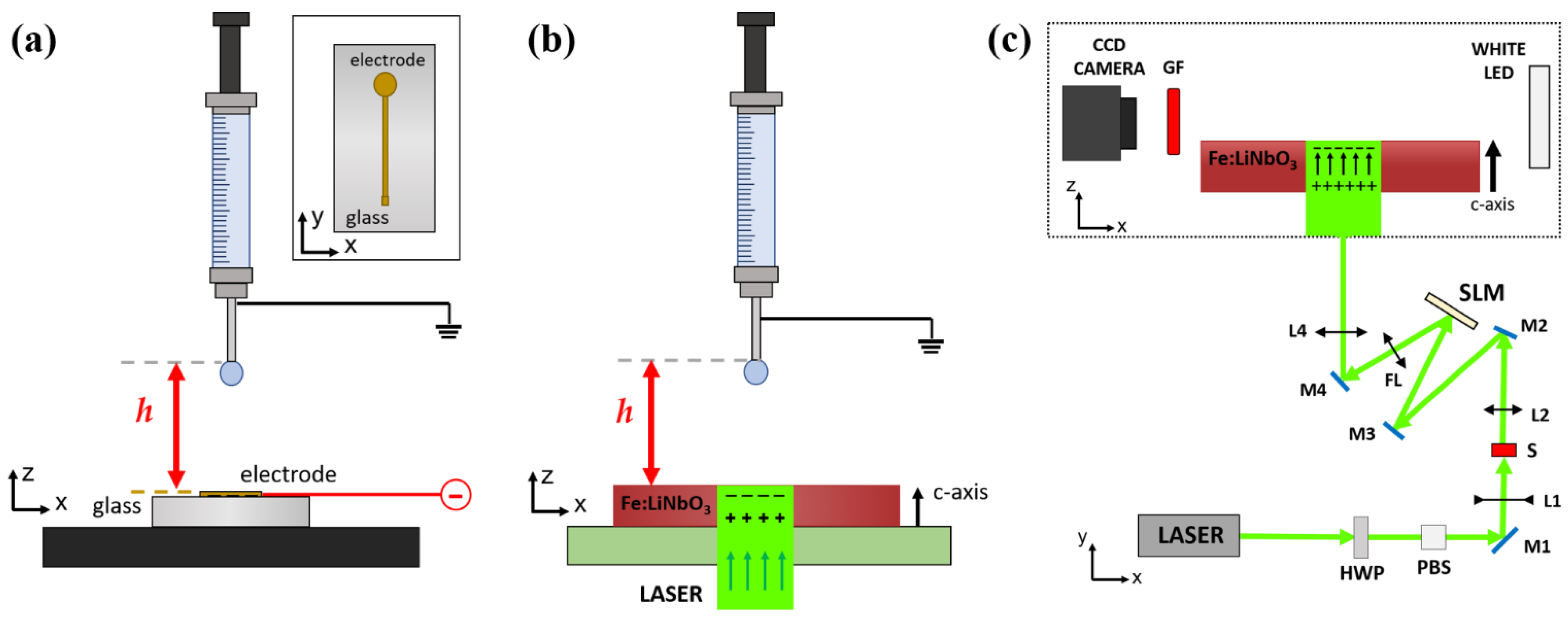
2.2. Dielectrophoretic Force on a Water Droplet Generated by Photovoltaic and Electrostatic Charges

In this work, two distinct experimental setups have been used, both with the objective of evaluating the effect produced by surface charge accumulation on a droplet suspended above it, as shown in Figure 1. In the first setup, see Figure 1a, electrostatic charges are created on the surface of a conductive substrate, while in the second setup, see Figure 1b, charges are generated on the main faces of Fe:LiNbO3 crystals through the photovoltaic effect.
The experimental setup designed to generate an electrostatic field below the pendant droplet and to evaluate the resulting dielectrophoretic force (E–DEP) is shown in Figure 1a. Ultrapure water droplets (resistivity 18.2 MΩ·cm) of known volume (Ω = 2.7 μL) are generated with a computer-controlled syringe pump (PHD 22/2000, Harvard apparatus) equipped with a glass syringe (1 mL, SGE) that mounts a stainless steel needle with an outer diameter of 0.2 mm. The droplet remains attached to the needle due to capillarity, assuming the conventional pendant droplet shape [34,35,37]. A CCD camera (Basler acA1300–200 μm) equipped with a telecentric objective is used to collect the lateral profile of the droplet, while a white LED provides back illumination. Below the needle, a glass slide is coated with a gold electrode deposited by magnetron-sputtering having a keyhole shape. In detail, the latter is formed by a circular 4 mm diameter spot connected to a 0.2 × 50 mm2 stripe (see inset in Figure 1a). The center of the circular part of the electrode is aligned with the needle of the syringe placed above. A high-voltage power supply provides a tunable voltage to the gold electrode up to 2000 V, while the needle is grounded. During a typical experiment, the distance h between the needle and the electrode is fixed, and the voltage is progressively increased until the droplet falls.
The setup to evaluate the dielectrophoretic force due to the photovoltaic effect (P–DEP) is schematically shown in Figure 1b,c. It presents the same components as the previously presented experimental setup for pendant droplet generation and imaging. The Fe:LiNbO3 crystal is placed on a three-axes motorized sample holder (M126.CG Linear Slide Translational Stage, PI) designed to allow illumination from the bottom. The light pattern projected on the sample is achieved by a linearly polarized laser beam (Class 4, Azur Light Systems, power 1 W max, λ = 532 nm, Pessac, France). The gaussian beam emitted by the laser is modulated in phase by a spatial light modulator (Pluto-NIR-011, Holoeye Photonics, Berlin, Germany) to project on the Fe:LiNbO3 crystal a circular spot having uniform light intensity and diameter d = 4 mm. The uniform light spot generated by the spatial light modulator yields a charged area with sharper contours than in the case of a gaussian beam, which would produce an expanding charge distribution with exposure time [24]. A properly tilted mirror ensures that the incident light beam illuminates the Fe:LiNbO3 crystal perpendicularly to its main z-cut surfaces and that the circular spot is aligned with the needle placed above. The intensity of the light pattern on the sample can be tuned between 0 and I = 11.1 kW/m2 using a half-wave plate (HWP) coupled with a polarizer beam splitter (PBS). An emission filter (GF, MF620-52, Thorlabs, Newton, NJ, USA) is placed in front of the objective to remove any residual reflection of the laser beam on the droplet. In analogy to the electrostatic case, during a typical experiment, the distance h between the needle and the upper Fe:LiNbO3 surface is fixed; then the laser light is turned on and the time required to induce the droplet to fall is measured. After each measurement run, the crystal is fully discharged by immersing it in water for about 20 min.

3. Results and Discussion

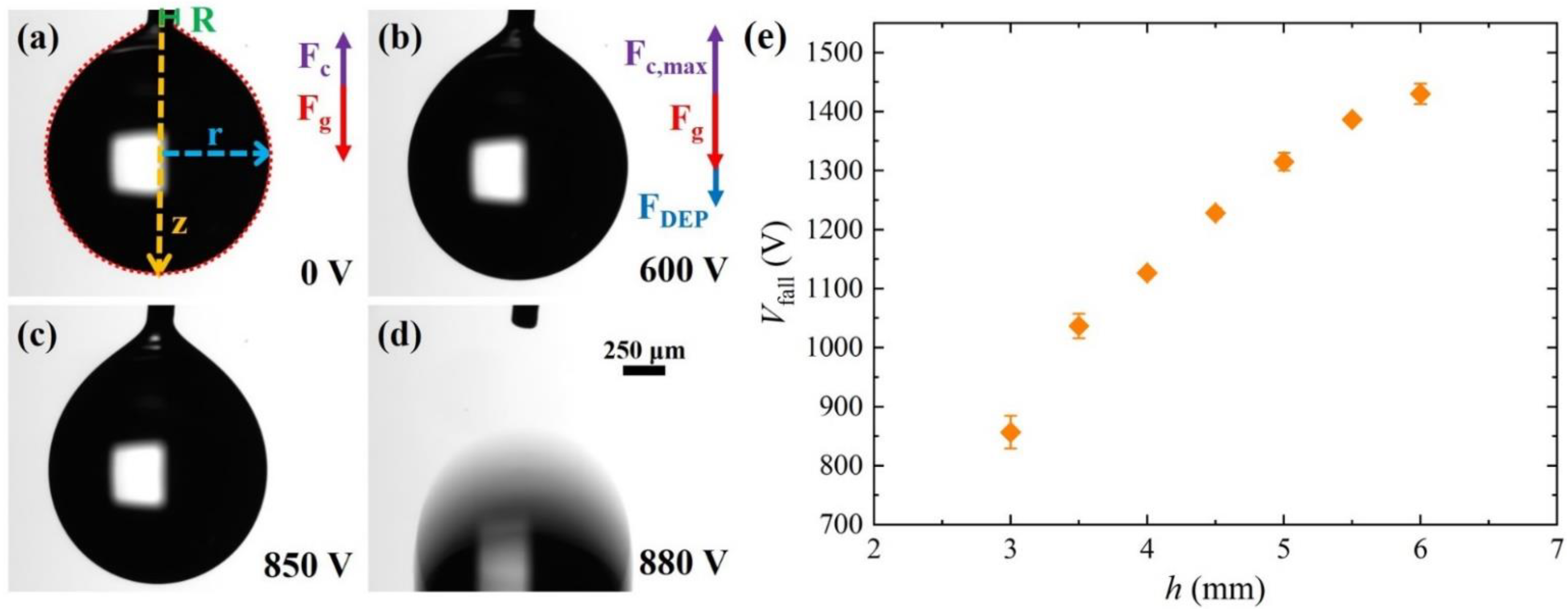
3.1. Dielectrophoretic Force on Pendant Droplet: Electrostatic Effect (E–DEP)

In a typical pendant droplet configuration, the droplet formed at the tip of the needle remains suspended because the capillary force F c acting along the contact line balances the droplet weight F g . The maximum capillary force F c , m a x exerted on a needle of external radius R can be approximated as follows [38]:
F c , m a x = 2 π R γ ψ
where γ is the surface tension of the droplet liquid and ψ is a correction factor depending on the droplet volume Ω. In our case, we used water droplets of Ω = 2.7 ± 0.1 µL, resulting in ψ = 0.93 , with a measured surface tension γ = 72 ± 1 mJ/m2. Since the needle has radius R = 0.1 mm, Formula (2) yields F c , m a x = 41.8 ± 0.8   µN. If a charged electrode is placed underneath, the water droplet, assumed to be a pure dielectric with no free charges, is attracted downward due to the dielectrophoretic force F D E P .
Figure 2a shows the characteristic geometry of a water droplet suspended to the needle in the absence of an electric field. The distance of the needle tip from the electrode is h = 3 mm. As a result of the pull action of the weight F g , the shape of the droplet is not spherical, but rather an elongated pear-like shape. When a voltage is applied to the electrode, the droplet becomes more elongated due to the contribution of the dielectrophoretic force F D E P , which is parallel to the direction of F g , as shown in Figure 2b. As the voltage is increased, the deformation becomes slightly more pronounced, see Figure 2c, until at Vfall = 880 V, the droplet detaches from the needle and falls, see Figure 2d and Video S1. This means that at Vfall, the pull action of the dielectrophoretic force and the droplet weight overcome the maximum capillary force exerted by the needle and, thus, we get the following equation:
F D E P = F c , m a x F g = 15 ± 1.3   µ N
The results of the voltage Vfall as a function of height h are plotted in the graph of Figure 2e, where each data point is the mean of at least three repeated measurements and the error bars represent the corresponding standard deviations. As expected, Vfall increases with h because, for a given voltage, the electric field experienced by the droplet decays with the distance from the electrode.
An alternative method to estimate the dielectrophoretic force is to analyze the curvature of the contour of a pendant droplet. When the droplet is at equilibrium, the hydrostatic pressure jump across the interface equalizes the Laplace pressure for each height z along the droplet [37], seen below:
ρ g * z = γ C
where ρ = 997 kg/m3 is the water density at T = 25 °C, g * is the effective gravitational acceleration [39] and C is the curvature at the surface. Because the dielectrophoretic force acts in the same direction as gravity, the total pull experienced by the droplet can be expressed as follows:
F g + F D E P = ϱ V g + F D E P = ϱ V g ( 1 + F D E P ϱ V g ) ϱ V g *
In other words, the effective gravitational acceleration g * = ϱ V g ( 1 + F D E P ϱ V g ) quantifies the dielectrophoretic force; in the absence of an electric field, g * = g , otherwise g * > g . At each point r(z) of the surface, as shown in Figure 1a, the curvature can be parametrized in cylindrical coordinates, as follows [29]:
C = d 2 r d z 2 ( 1 + ( d r d z ) 2 ) 3 2 + 1 r ( 1 + ( d r d z ) 2 ) 1 / 2
The droplet profile can be fitted numerically [40], according to Equations (2)–(4), to extract g * , given ρ and γ. Thus, we have applied this procedure to the droplet profiles extracted from the video frames, right before the droplet fall. In this way, it is possible to estimate the value of F D E P required to detach the water droplet. Table 1 shows the results obtained for h ≥ 3 mm; for shorter distances, the droplet touches the surface during elongation. All F E D E P values agree within one standard deviation and their mean value F ¯ E D E P = 14 ± 2 µN is perfectly consistent with the value of 15.1 ± 1.3 µN, deduced above.

3.2. Dielectrophoretic Force on the Pendant Droplet: Photovoltaic Effect (P–DEP)

An analogous behavior is observed illuminating the Fe:LiNbO3 crystal, as shown in Figure 3 for h = 3 mm and Video S2. Initially, the laser is off and the droplet is deformed due to the balance between the capillary and gravity forces, see Figure 3a. When the light is turned on at t = 0 s, charges are expected to accumulate progressively on the Fe:LiNbO3 surfaces in the illuminated area [16] and, as a consequence, the droplet elongates due to the dielectrophoretic force, as shown in Figure 3b. During illumination, this elongation progressively increases, see Figure 3c, until at a time tfall = 6.76 s, the droplet detaches from the needle and falls down, see Figure 3d. This evolution resembles that discussed in Figure 2a–d, observed by increasing the applied voltage. The graph in Figure 3e shows the variation of the characteristic time tfall with the distance h between 3 and 6 mm and for different light intensities; each data point is the mean of at least three measurements, repeated under the same conditions, and the error bars represent the corresponding standard deviations. The light intensities were chosen to yield tfall sufficiently low to significantly limit the evaporation of the droplets during the measurements. For a given illumination intensity I, tfall increases with h, particularly for I = 5.2 kW/m2, while for a fixed h, the time required to detach the droplet decreases with increasing I. These results can be rationalized by taking into account the temporal evolution of the light-induced electric field within the lithium niobate crystal [16,17], as follows:
E i n = E s a t ( 1 e t / τ )
where the amplitude E s a t is the highest electric field achievable within the crystal and is proportional to the amount of Fe3+. The parameter τ represents the photovoltaic time constant and is defined as τ = k / ( R · I ) , where k a is constant typical of the material [16,17], R = [Fe2+]/[Fe3+] the reduction degree. Therefore, because the electric field experienced by the droplet decays with the distance from the crystal, at higher values of h, the photoinduced charge density required to detach the droplet must increase, and this implies, for a given I, longer illumination times. Similarly, using higher I leads to faster charge accumulation and, thus, given a certain h, tfall decreases with increasing I, see Figure 3e.
The value of F P D E P , generated by the charges photoinduced on the Fe:LiNbO3 crystal, is deduced from the analysis of the droplet contour immediately before the droplet falls, as done in the previous section, to compare it to the force computed in Equation (3). As reported in Table 1, for I = 8.8 kW/m2, all F P D E P , the values are rather similar, confirming that the force necessary to overcome the capillary force is always the same at any distance h, although the required illumination time tfall differs by more than one order of magnitude. Importantly, their mean value F ¯ P D E P = 13.3 ± 1.5 μN in the case of the photovoltaic effect is compatible with the value F ¯ E D E P = 14 ± 2 μN found in the electrostatic experiment. This confirms the analogy between the two experiments and the capability of the pendant droplet to work as a probe for the dielectrophoretic force.

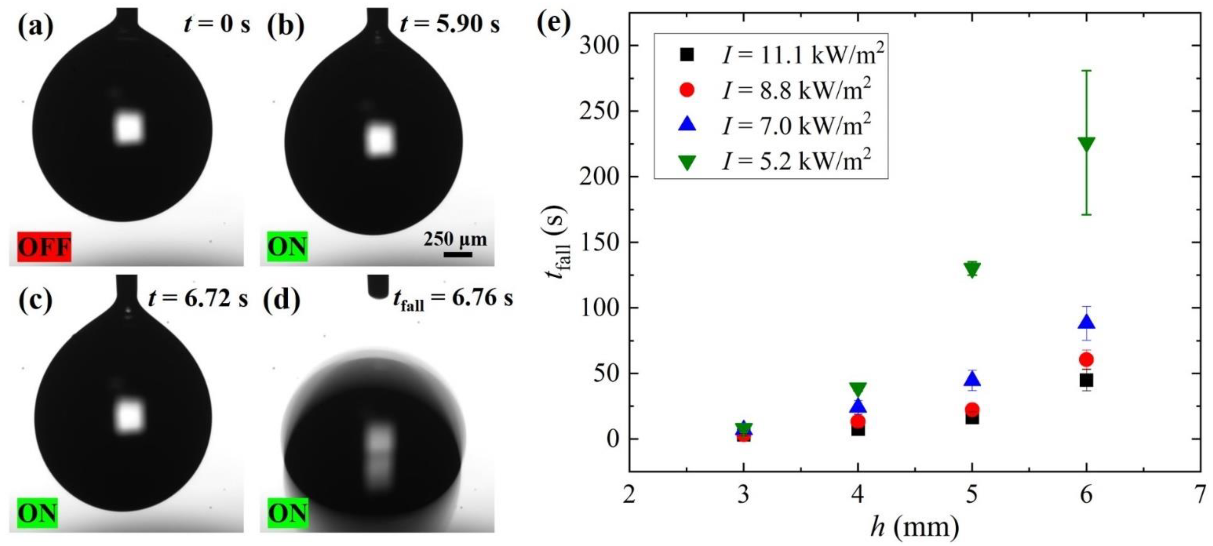
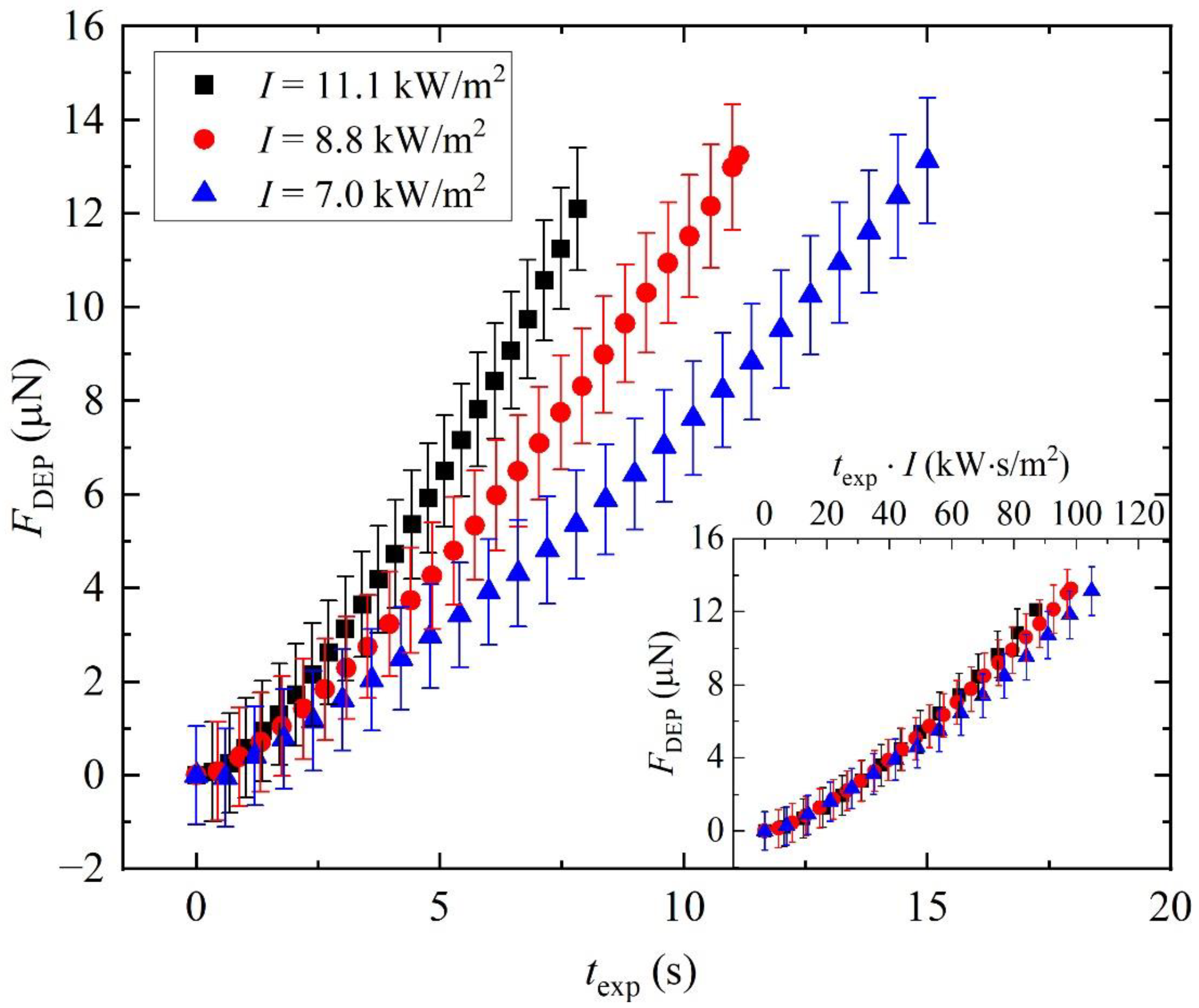
3.3. Dynamics of the Dielectrophoretic Force by the Photovoltaic Effect (P–DEP)

The pendant droplet method can also be applied to investigate time-dependent processes, such as charge accumulation on Fe:LiNbO3 surfaces. As an example, Figure 4 shows the temporal evolution of the F P D E P acting on the droplet attached to the needle, distanced h = 4 mm from the top surface of the Fe:LiNbO3 crystal. The force is plotted against the exposure time texp of the crystal to different light intensities. It is determined by analyzing each video frame acquired during the illumination. The final points of each curve correspond to the frame at which the droplet falls. As expected, this event is independent of the beam intensity and yields similar F P D E P values, between 12.1 μN and 13.2 μN, in very good agreement, within one standard deviation, with those listed in Table 1. The increase over time of F P D E P reflects the increase in the evanescent field, due to the photovoltaic effect predicted by Equation (6). More precisely, Equation (1) indicates that the temporal evolution of F P D E P ( t ) is the same as that of E i n ( t ) 2 . Since the characteristic time constant τ is inversely proportional to the light intensity, this explains why F P D E P grows more slowly at lower I. Furthermore, if we plot the same data in terms of the so-called light exposure rate, equal to t exp · I , [24] we expect from Equation (6) that all the data collapse on the same master curve, which depends only on material properties of the Fe:LiNbO3 crystal. The graph inset confirms the validity of this scaling.

4. Conclusions

We have described a simple technique to measure the dielectrophoretic force acting on a water droplet due to an electric field. It consists of a variation of the pendant droplet technique, commonly employed to derive the surface tension of a liquid. We have successfully applied it to probe the forces generated in standard electrowetting (electric field due to the voltage generated by a power supply) and optowetting (electric field due to the illumination of a lithium niobate crystal) applications. It does not require sophisticated set-ups, can be easily applied to different experimental situations and provides reliable spatial and temporal resolutions. We feel that this pendant droplet technique can yield quantitative information relevant for the design and characterization of microfluidic devices, using electric fields for the droplet actuation.

Supplementary Materials

The following are available online at https://www.mdpi.com/article/10.3390/mi13020316/s1, Video S1: Detachment of a pendant water droplet due to the electric field induced by the voltage applied by the E–DEP experimental setup. Video S2: Detachment of a pendant water droplet due to the illumination of an iron-doped lithium niobate crystal by the P–DEP experimental setup.

Author Contributions

Conceptualization, D.F., A.M., A.Z. and G.M.; methodology, A.M., S.C., M.C., D.F. and A.Z.; data curation, S.C., A.M. and D.F.; writing—original draft preparation, A.M., S.C., D.F., A.Z., M.P., C.S. and G.M.; supervision, D.F., A.Z., G.M., C.S. and M.P.; funding acquisition, D.F., G.M., A.Z. and C.S. All authors have read and agreed to the published version of the manuscript.

Funding

This research was funded by the University of Padova through STARS grant—EXODROP, BIRD Grant 2021–BiodivSeq, BIRD 165523/16 “Biosensing Light-driven Tools in Advanced opto-microfluidic Lithium niobate Platform” and BIRD207923/20 “Fuel-driven processes in DNA-biosensors investigated at the single-molecule level by optical tweezers”.

Data Availability Statement

Data are contained within the article or Supplementary Materials.

Acknowledgments

The authors are particularly grateful to Giorgio Delfitto, for his valuable technical assistance, and Boris Kalinic, for assistance in the sputtering sample preparation.

Conflicts of Interest

The authors declare no conflict of interest.

References

  1. Mistura, G.; Pierno, M. Drop mobility on chemically heterogeneous and lubricant-impregnated surfaces. Adv. Phys. X 2017, 2, 591–607. [Google Scholar] [CrossRef] [Green Version]
  2. Malinowski, R.; Parkin, I.P.; Volpe, G. Advances towards programmable droplet transport on solid surfaces and its applications. Chem. Soc. Rev. 2020, 49, 7879–7892. [Google Scholar] [CrossRef] [PubMed]
  3. Cho, S.K.; Moon, H.J.; Kim, C.J. Creating, transporting, cutting, and merging liquid droplets by electrowetting-based actuation for digital microfluidic circuits. J. Microelectromech. Syst. 2003, 12, 70–80. [Google Scholar] [CrossRef] [Green Version]
  4. McHale, G.; Brown, C.V.; Newton, M.I.; Wells, G.G.; Sampara, N. Dielectrowetting driven spreading of droplets. Phys. Rev. Lett. 2011, 107, 186101. [Google Scholar] [CrossRef] [Green Version]
  5. Khalil, K.S.; Mahmoudi, S.R.; Abu-dheir, N.; Varanasi, K.K. Active surfaces: Ferrofluid-impregnated surfaces for active manipulation of droplets. Appl. Phys. Lett. 2014, 105, 041604. [Google Scholar] [CrossRef]
  6. Rigoni, C.; Ferraro, D.; Carlassara, M.; Filippi, D.; Varagnolo, S.; Pierno, M.; Talbot, D.; Abou-Hassan, A.; Mistura, G. Dynamics of ferrofluid drops on magnetically patterned surfaces. Langmuir 2018, 34, 8917–8922. [Google Scholar] [CrossRef]
  7. Ichimura, K.; Oh, S.K.; Nakagawa, M. Light-driven motion of liquids on a photoresponsive surface. Science 2000, 288, 1624–1626. [Google Scholar] [CrossRef] [Green Version]
  8. Dattilo, D.; Armelao, L.; Fois, G.; Mistura, G.; Maggini, M. Wetting properties of flat and porous silicon surfaces coated with a spiropyran. Langmuir 2007, 23, 12945–12950. [Google Scholar] [CrossRef]
  9. Xia, F.; Feng, L.; Wang, S.T.; Sun, T.L.; Song, W.L.; Jiang, W.H.; Jiang, L. Dual-responsive surfaces that switch superhydrophilicity and superhydrophobicity. Adv. Mater. 2006, 18, 432–436. [Google Scholar] [CrossRef]
  10. Wixforth, A.; Strobl, C.; Gauer, C.; Toegl, A.; Scriba, J.; von Guttenberg, Z. Acoustic manipulation of small droplets. Anal. Bioanal. Chem. 2004, 379, 982–991. [Google Scholar] [CrossRef]
  11. Sartori, P.; Guglielmin, E.; Ferraro, D.; Filippi, D.; Zaltron, A.; Pierno, M.; Mistura, G. Motion of Newtonian drops deposited on liquid-impregnated surfaces induced by vertical vibrations. J. Fluid Mech. 2019, 876, R4. [Google Scholar] [CrossRef]
  12. Li, J.S.; Ueda, E.; Paulssen, D.; Levkin, P.A. Slippery lubricant-infused surfaces: Properties and emerging applications. Adv. Funct. Mater. 2019, 29, 1802317. [Google Scholar] [CrossRef] [Green Version]
  13. Lou, X.D.; Huang, Y.; Yang, X.; Zhu, H.; Heng, L.P.; Xia, F. External stimuli responsive liquid-infused surfaces switching between slippery and nonslippery states: Fabrications and applications. Adv. Funct. Mater. 2020, 30, 1901130. [Google Scholar] [CrossRef]
  14. Mugele, F.; Baret, J.C. Electrowetting: From basics to applications. J. Phys. Condens. Matter 2005, 17, R705–R774. [Google Scholar] [CrossRef]
  15. Hao, C.L.; Liu, Y.H.; Chen, X.M.; He, Y.C.; Li, Q.S.; Li, K.Y.; Wang, Z.K. Electrowetting on liquid-infused film (EWOLF): Complete reversibility and controlled droplet oscillation suppression for fast optical imaging. Sci. Rep. 2014, 4, 6846. [Google Scholar] [CrossRef] [Green Version]
  16. Buse, K. Light-induced charge transport processes in photorefractive crystals. 1. Models and experimental methods. Appl. Phys. B Lasers Opt. 1997, 64, 273–291. [Google Scholar] [CrossRef]
  17. Frejlich, J. Photorefractive Materials: Fundamental Concepts, Holographic Recording and Materials Characterization; Wiley-Interscience: Hoboken, NJ, USA, 2007. [Google Scholar]
  18. Puerto, A.; Coppola, S.; Miccio, L.; Vespini, V.; Garcia-Cabanes, A.; Carrascosa, M.; Ferraro, P. Droplet ejection and liquid jetting by visible laser irradiation in pyro-photovoltaic Fe-doped LiNbO3 platforms. Adv. Mater. Interfaces 2021, 8, 2101164. [Google Scholar] [CrossRef]
  19. Glass, A.M.; Linde, D.v.d.; Negran, T.J. High-voltage bulk photovoltaic effect and the photorefractive process in LiNbO3. Appl. Phys. Lett. 1974, 25, 233–235. [Google Scholar] [CrossRef]
  20. Zhang, X.Z.; Wang, J.Q.; Tang, B.Q.; Tan, X.H.; Rupp, R.A.; Pan, L.T.; Kong, Y.F.; Sun, Q.; Xu, J.J. Optical trapping and manipulation of metallic micro/nanoparticles via photorefractive crystals. Opt. Express 2009, 17, 9981–9988. [Google Scholar] [CrossRef]
  21. Carrascosa, M.; Garcia-Cabanes, A.; Jubera, M.; Ramiro, J.B.; Agullo-Lopez, F. LiNbO3: A photovoltaic substrate for massive parallel manipulation and patterning of nano-objects. Appl. Phys. Rev. 2015, 2, 040605. [Google Scholar] [CrossRef] [Green Version]
  22. Esseling, M.; Zaltron, A.; Horn, W.; Denz, C. Optofluidic droplet router. Laser Photon. Rev. 2015, 9, 98–104. [Google Scholar] [CrossRef]
  23. Gazzetto, M.; Nava, G.; Zaltron, A.; Cristiani, I.; Sada, C.; Minzioni, P. Numerical and experimental study of optoelectronic trapping on iron-doped lithium niobate substrate. Crystals 2016, 6, 123. [Google Scholar] [CrossRef] [Green Version]
  24. Munoz-Martinez, J.F.; Alcazar, A.; Carrascosa, M. Time evolution of photovoltaic fields generated by arbitrary light patterns in z-cut LiNbO3:Fe: Application to optoelectronic nanoparticle manipulation. Opt. Express 2020, 28, 18085–18102. [Google Scholar] [CrossRef] [PubMed]
  25. Villarroel, J.; Burgos, H.; Garcia-Cabanes, A.; Carrascosa, M.; Blazquez-Castro, A.; Agullo-Lopez, F. Photovoltaic versus optical tweezers. Opt. Express 2011, 19, 24320–24330. [Google Scholar] [CrossRef] [PubMed]
  26. Chen, L.P.; Li, S.B.; Fan, B.L.; Yan, W.B.; Wang, D.H.; Shi, L.H.; Chen, H.J.; Ban, D.C.; Sun, S.H. Dielectrophoretic behaviours of microdroplet sandwiched between LN substrates. Sci. Rep. 2016, 6, 29166. [Google Scholar] [CrossRef] [Green Version]
  27. Eggert, H.A.; Kuhnert, F.Y.; Buse, K.; Adleman, J.R.; Psaltis, D. Trapping of dielectric particles with light-induced space-charge fields. Appl. Phys. Lett. 2007, 90, 241909. [Google Scholar] [CrossRef] [Green Version]
  28. Jones, T.B. Electromechanics of Particles; Cambridge University Press: New York, NY, USA, 1995. [Google Scholar]
  29. Lucchetti, L.; Kushnir, K.; Zaltron, A.; Simoni, F. Liquid crystal cells based on photovoltaic substrates. J. Eur. Opt. Soc. Rapid Publ. 2016, 11, 16007. [Google Scholar] [CrossRef] [Green Version]
  30. Fan, B.L.; Li, F.F.; Chen, L.P.; Shi, L.H.; Yan, W.B.; Zhang, Y.Q.; Li, S.B.; Wang, X.L.; Wang, X.; Chen, H.J. Photovoltaic manipulation of water microdroplets on a hydrophobic LiNbO3 substrate. Phys. Rev. Appl. 2017, 7, 064010. [Google Scholar] [CrossRef]
  31. Puerto, A.; Mendez, A.; Arizmendi, L.; Garcia-Cabanes, A.; Carrascosa, M. Optoelectronic manipulation, trapping, splitting, and merging of water droplets and aqueous biodroplets based on the bulk photovoltaic effect. Phys. Rev. Appl. 2020, 14, 024046. [Google Scholar] [CrossRef]
  32. Tang, X.; Li, W.; Wang, L.Q. Furcated droplet motility on crystalline surfaces. Nat. Nanotechnol. 2021, 16, 1106–1112. [Google Scholar] [CrossRef]
  33. Zhang, X.; Mugisha, E.R.; Mi, Y.H.; Liu, X.H.; Wang, M.T.; Gao, Z.X.; Gao, K.F.; Shi, L.H.; Chen, H.J.; Yan, W.B. Photovoltaic cycling to-and-fro actuation of a water-microdroplet for automatic repeatable solute acquisition on oil-infused hydrophobic LN:Fe surface. ACS Photonics 2021, 8, 639–647. [Google Scholar] [CrossRef]
  34. Berry, J.D.; Neeson, M.J.; Dagastine, R.R.; Chan, D.Y.C.; Tabor, R.F. Measurement of surface and interfacial tension using pendant drop tensiometry. J. Colloid Interface Sci. 2015, 454, 226–237. [Google Scholar] [CrossRef] [PubMed]
  35. Ferraro, D.; Serra, M.; Filippi, D.; Zago, L.; Guglielmin, E.; Pierno, M.; Descroix, S.; Viovy, J.L.; Mistura, G. Controlling the distance of highly confined droplets in a capillary by interfacial tension for merging on-demand. Lab Chip 2019, 19, 136–146. [Google Scholar] [CrossRef] [PubMed] [Green Version]
  36. Ciampolillo, M.V.; Zaltron, A.; Bazzan, M.; Argiolas, N.; Sada, C. Quantification of iron (Fe) in lithium niobate by optical absorption. Appl. Spectrosc. 2011, 65, 216–220. [Google Scholar] [CrossRef]
  37. De Gennes, P.G.; Brochard-Wyart, F.; Quéré, D. Capillarity and Wetting Phenomena: Drops, Bubbles, Pearls, Waves; Springer: New York, NY, USA, 2004. [Google Scholar]
  38. Lee, B.B.; Ravindra, P.; Chan, E.S. A critical review: Surface and interfacial tension measurement by the drop weight method. Chem. Eng. Commun. 2008, 195, 889–924. [Google Scholar] [CrossRef]
  39. Rigoni, C.; Pierno, M.; Mistura, G.; Talbot, D.; Massart, R.; Bacri, J.C.; Abou-Hassan, A. Static magnetowetting of ferrofluid drops. Langmuir 2016, 32, 7639–7646. [Google Scholar] [CrossRef]
  40. Daerr, A.; Mogne, A. Pendent_Drop: An ImageJ plugin to measure the surface tension from an image of a pendent drop. J. Open Res. Softw. 2016, 4, e3. [Google Scholar] [CrossRef] [Green Version]
Figure 1. (a) Experimental setup for the E–DEP evaluation. A glass slide coated with a gold electrode is connected to a voltage generator. The top view of the electrode is reported in the right-side box. (b) Experimental setup for P–DEP evaluation. Laser light illuminates the Fe:LiNbO3 crystal and creates a distribution of charges of opposite sign on the two main surfaces. (c) Schematic view of the optical path. A CCD camera and a white LED backlight are aligned to allow for a lateral view of the experimental area. The laser beam is expanded with lenses L1, L2 to illuminate the spatial light modulator (SLM) area. The desired light pattern is set and projected on the crystal by the Fourier lens (FL). Mirrors M1–M4 are used to guide the beam and bring it up to the vertical plane (x,z). The power of the beam is tuned by a half-wave plate (HWP) coupled with a polarizer beam splitter (PBS). A mechanical shutter (S) is used to control the illumination time. In both setups, a syringe pump provides the formation of a pendant droplet of known volume.
Micromachines 13 00316 g001
Figure 2. (ad) Sequence of snapshots showing the shape of a pendant droplet at increasing voltages applied to the underlying electrode. The graphical insets indicate the main geometric quantities and the forces involved. The distance of the needle tip from the electrode is h = 3 mm and the volume of the droplet is 2.7 μL. (e) Variation of the minimum voltage Vfall required to detach the droplet from the needle with distance h. If not visible, the error bars are the size of the symbols.
Micromachines 13 00316 g002
Figure 3. (ad) Sequence of snapshots showing the detachment of a pendant droplet caused by the charges generated on the surface of the underlying Fe:LiNbO3 crystal illuminated with an intensity I = 7.0 kW/m2. The distance of the needle tip from the crystal is h = 3 mm and the volume of the droplet is 2.7 μL. (e) Variation of the time tfall required to detach the droplet from the needle with distance h and for different light intensities I.
Micromachines 13 00316 g003
Figure 4. Variation of the dielectrophoretic force F P D E P induced by the photovoltaic effect over the exposure time t exp of the Fe:LiNbO3 acting on a pendant water droplet for different intensities I. The inset shows the same data plotted as a function of the light exposure rate t exp · I . The distance of the needle tip from the crystal is fixed at h = 4 mm and the volume of the droplet is 2.7 μL.
Micromachines 13 00316 g004
Table 1. The dielectrophoretic force required to detach the droplet from the needle evaluated at different heights h from the E–DEP and P–DEP experiments. The values of F P D E P refer to a light intensity I = 8.8 kW/m2 and a volume of the droplet Ω = 2.7 μL.
h
(mm)
F E D E P
(μN)
F P D E P
(μN)
3.0 ± 0.114.9 ± 1.514.2 ± 1.5
4.0 ± 0.115.8 ± 1.512.0 ± 1.4
5.0 ± 0.112.2 ± 1.4 12.0 ± 1.4
6.0 ± 0.111.9 ± 1.4 15.0 ± 1.5
F ¯ D E P 14 ± 213.3 ± 1.5
Publisher’s Note: MDPI stays neutral with regard to jurisdictional claims in published maps and institutional affiliations.

