
Compact 5G Nonuniform Transmission Line Interdigital Bandpass Filter for 5G/UWB Reconfigurable Antenna


Abstract
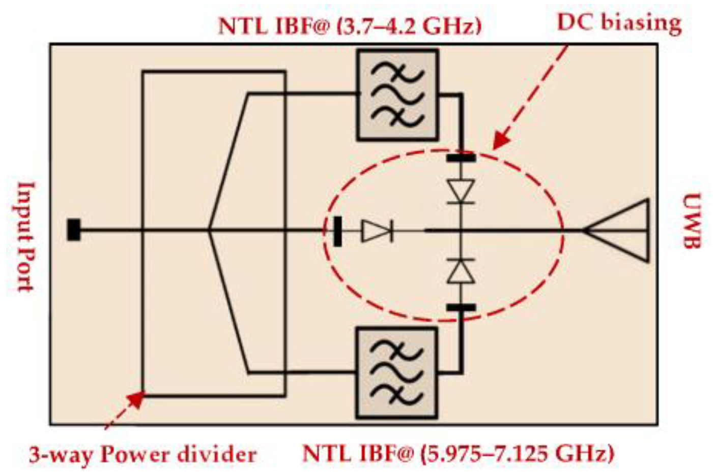
:1. Introduction
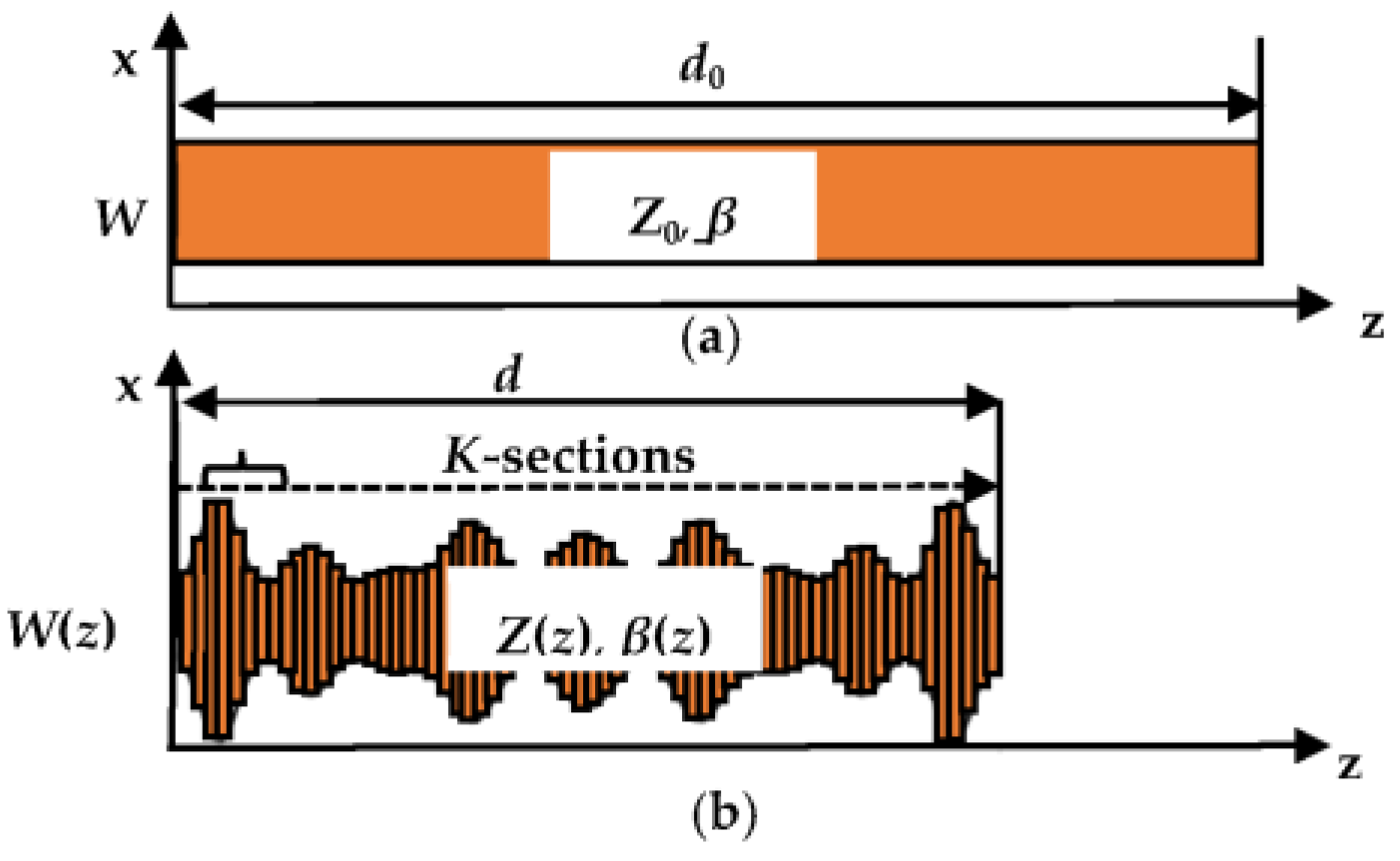
2. Nonuniform Transmission Lines (NTL) Theory
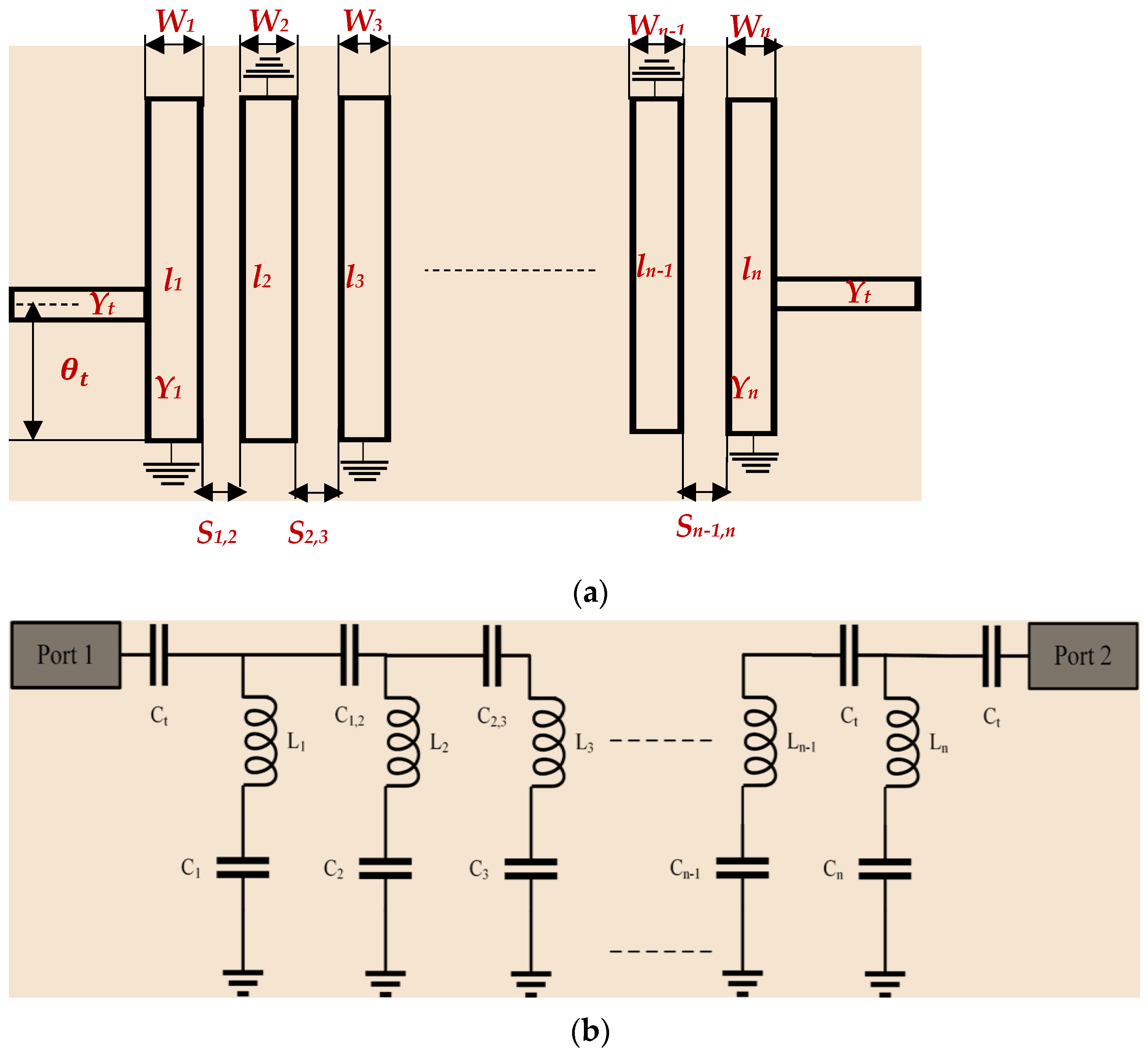
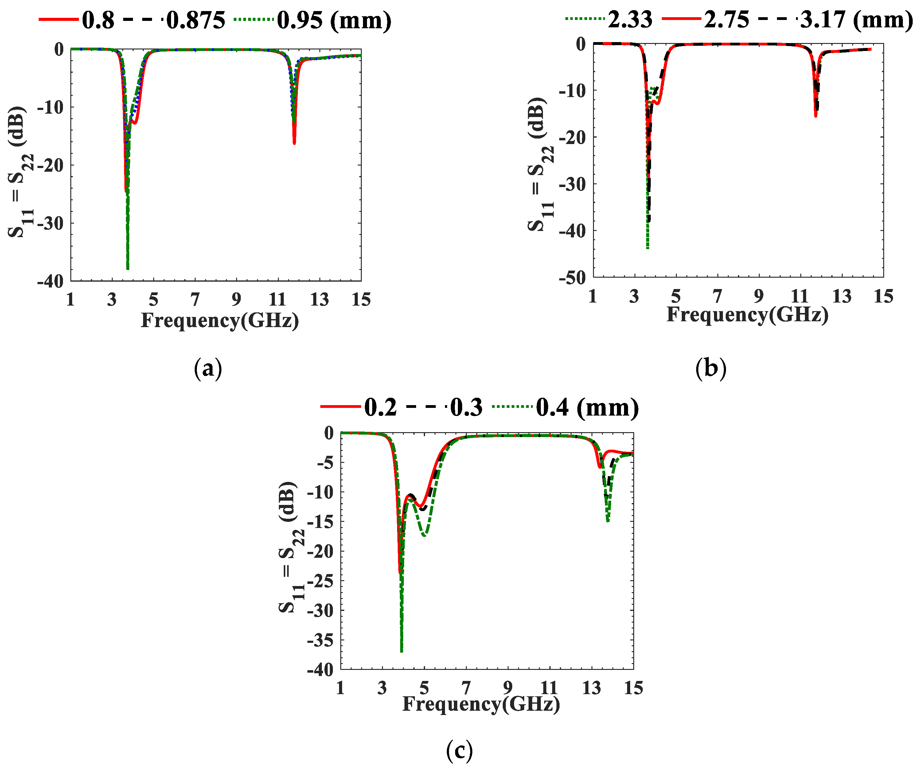
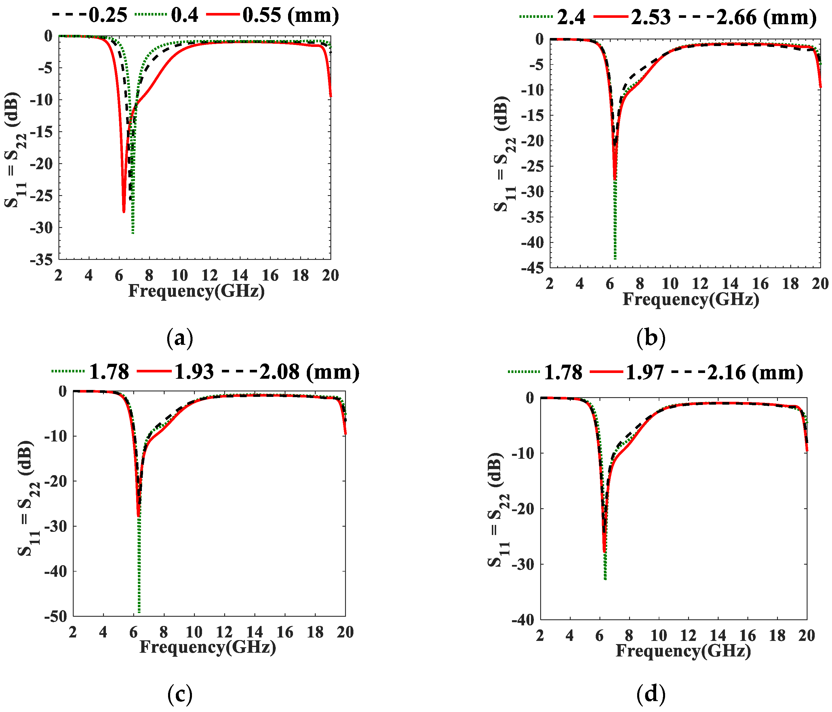
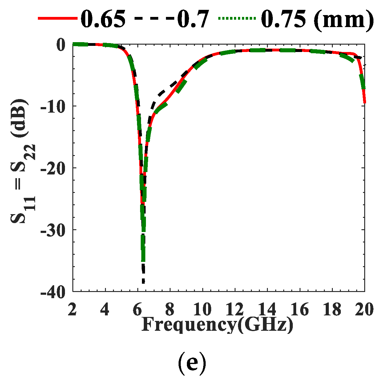
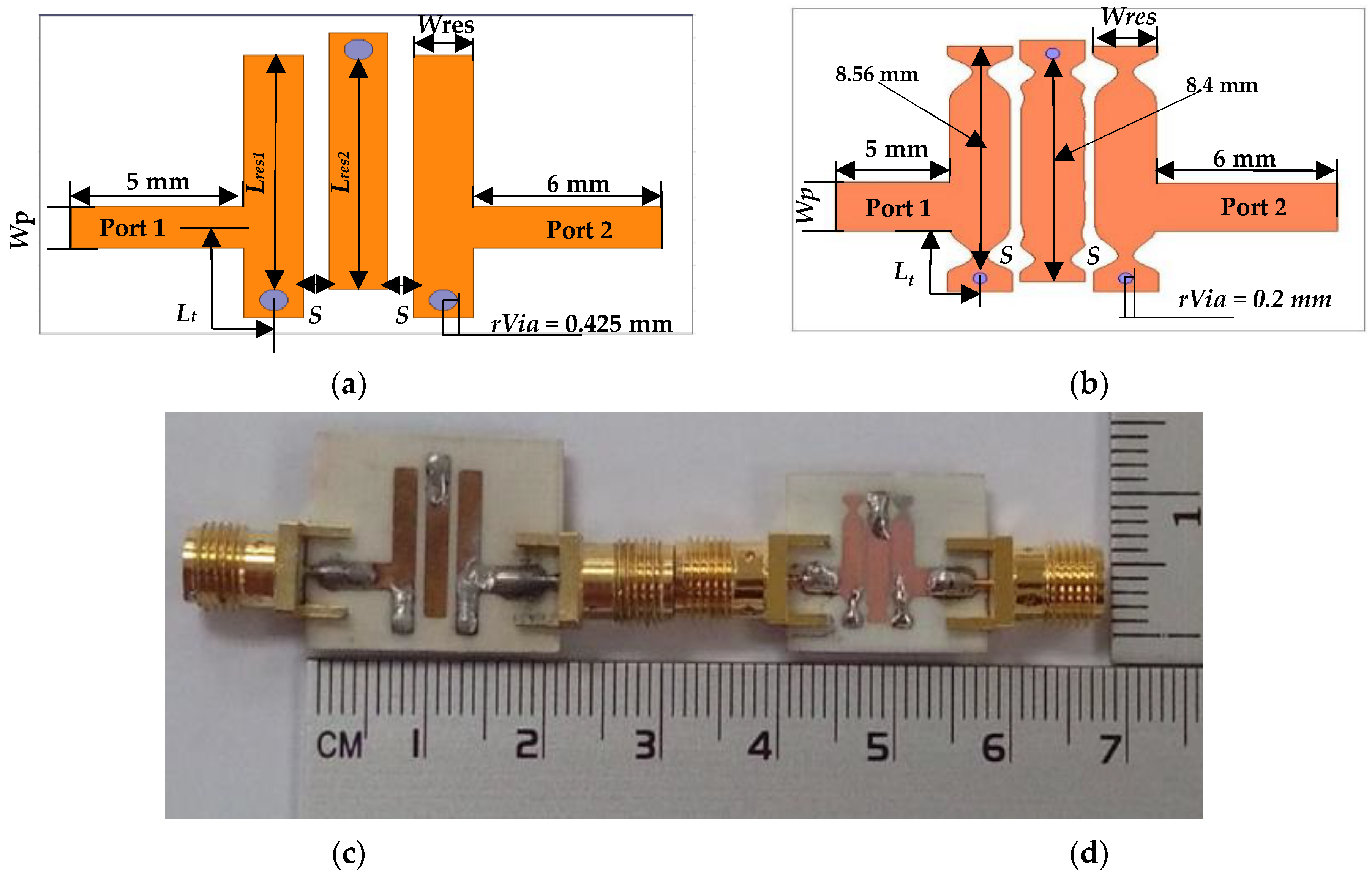
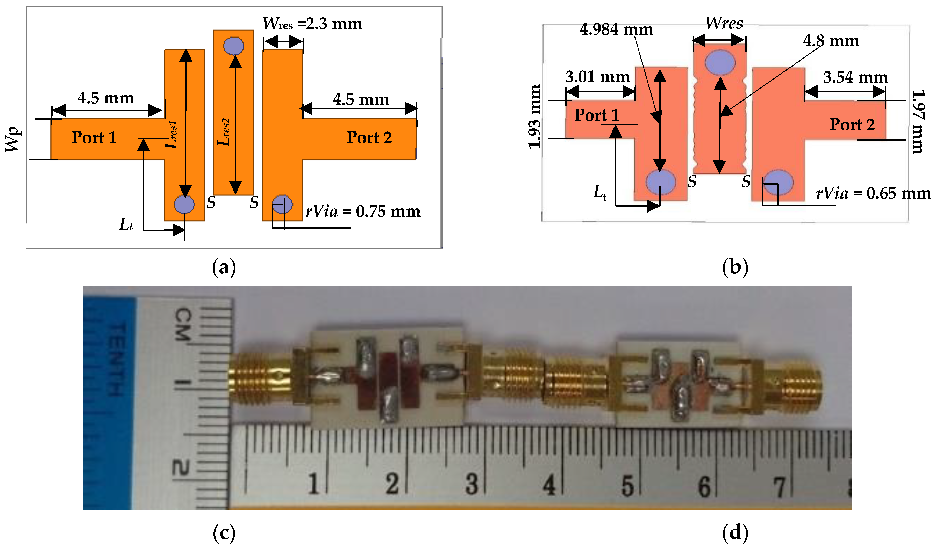
3. Design of The Proposed Compact NTL 3.95 and 6.55 GHz IBPFs
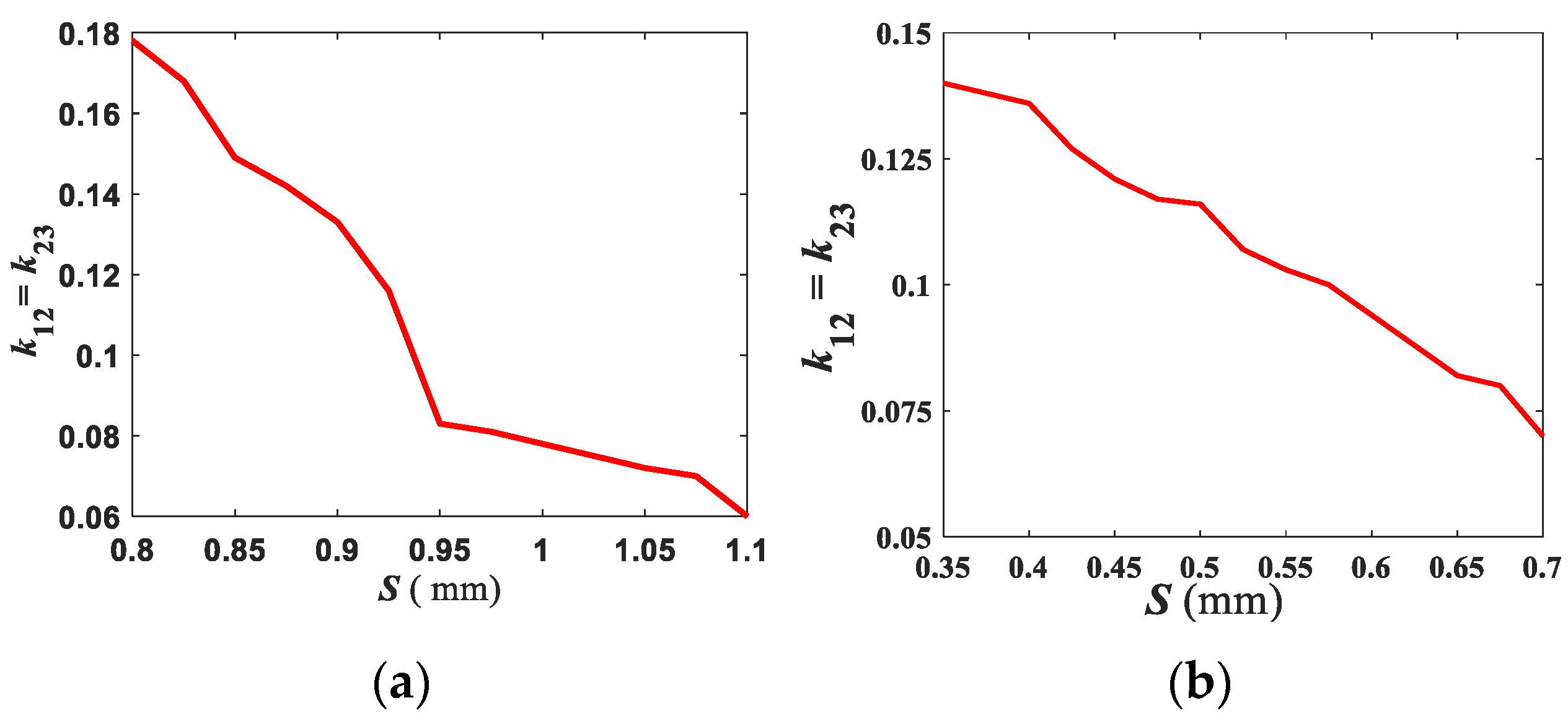
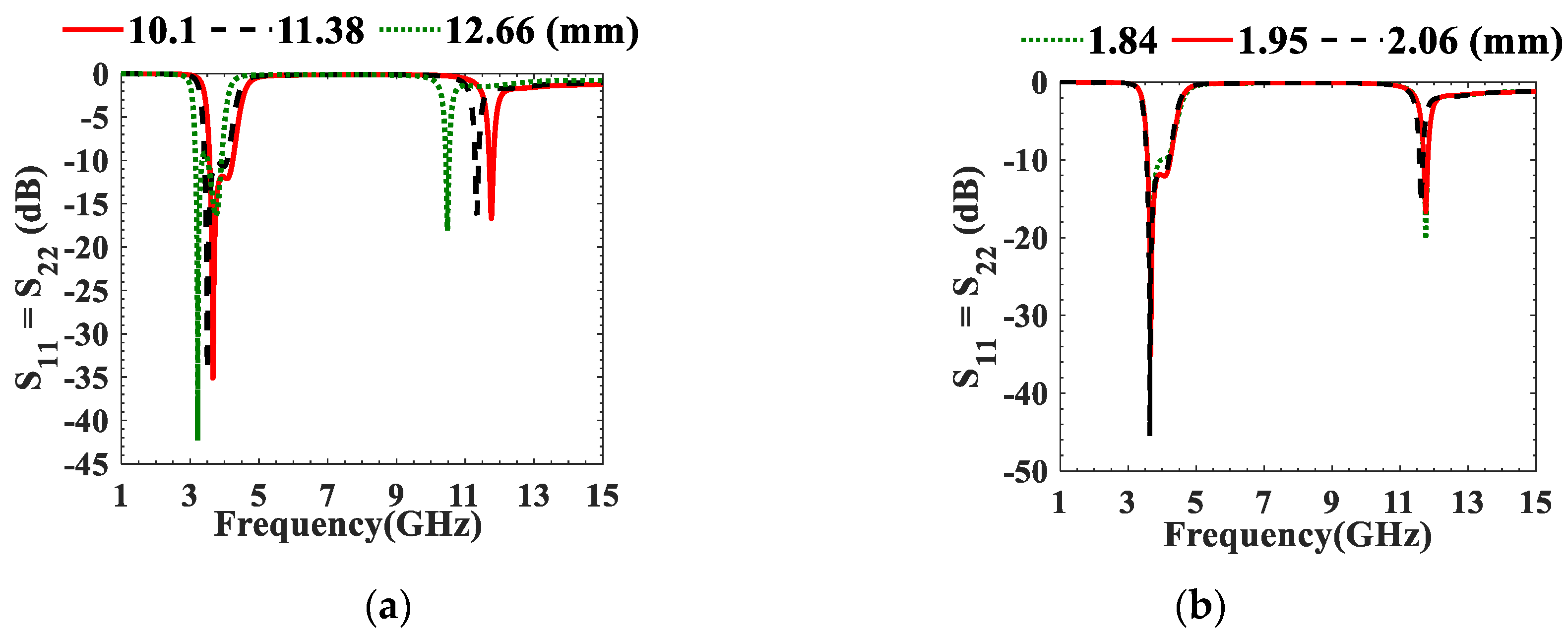
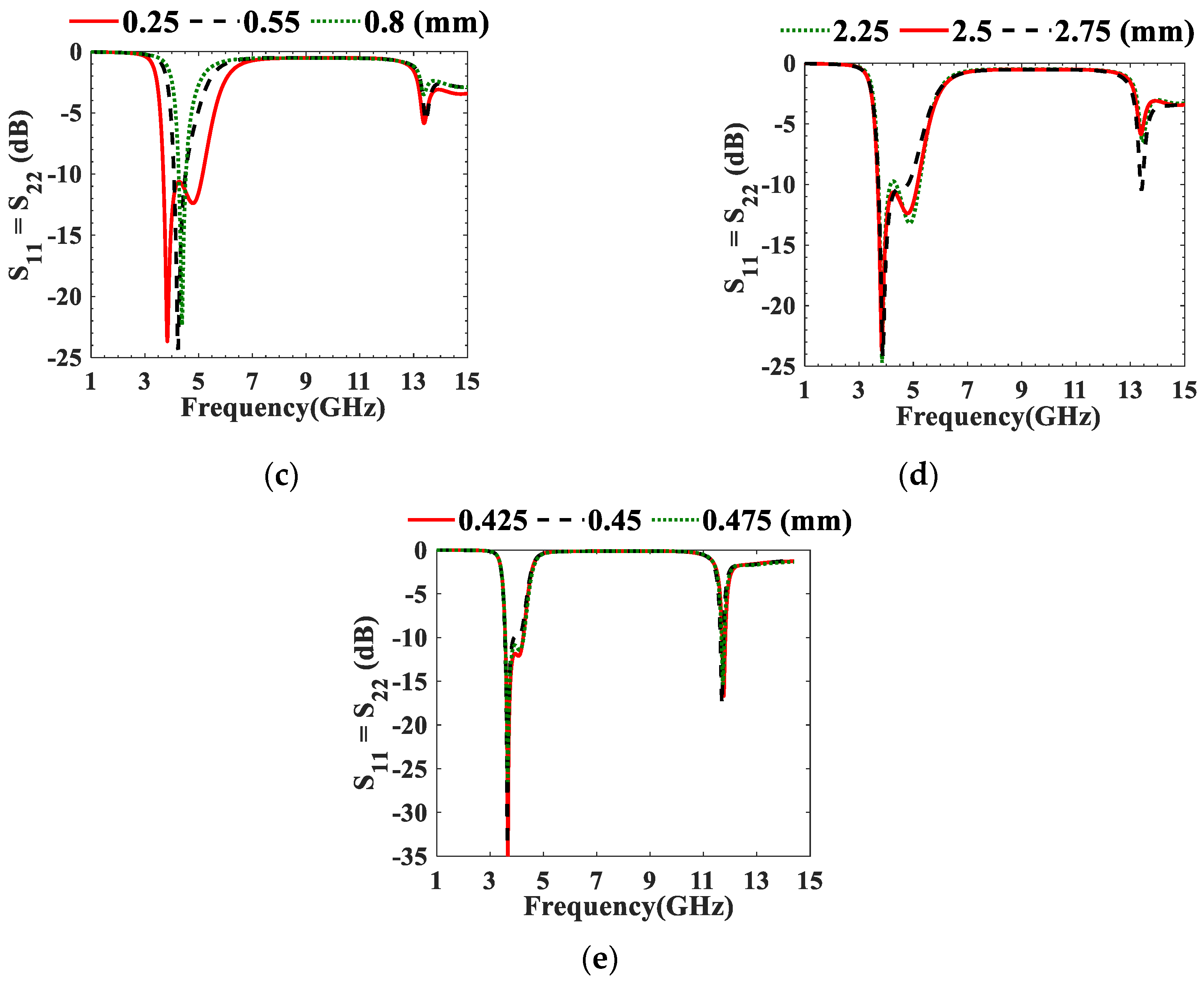
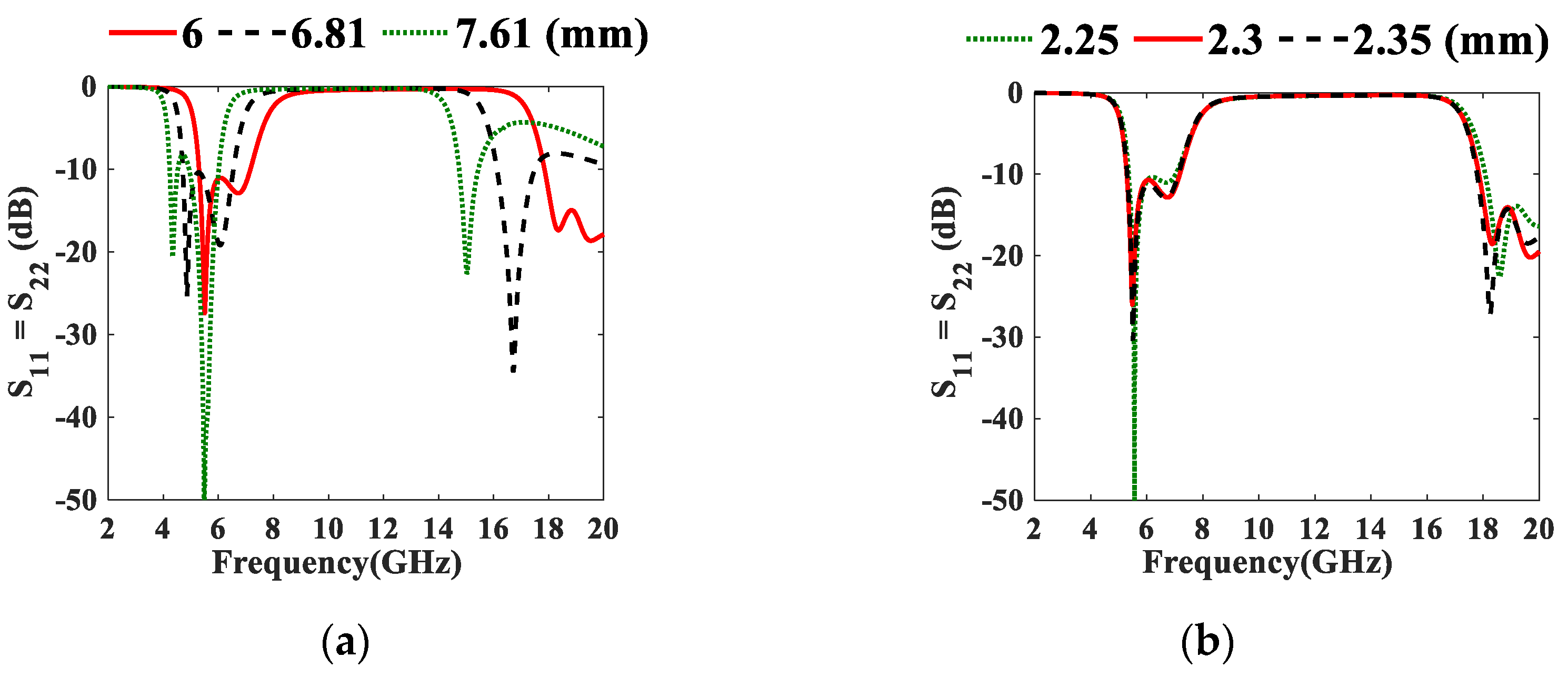
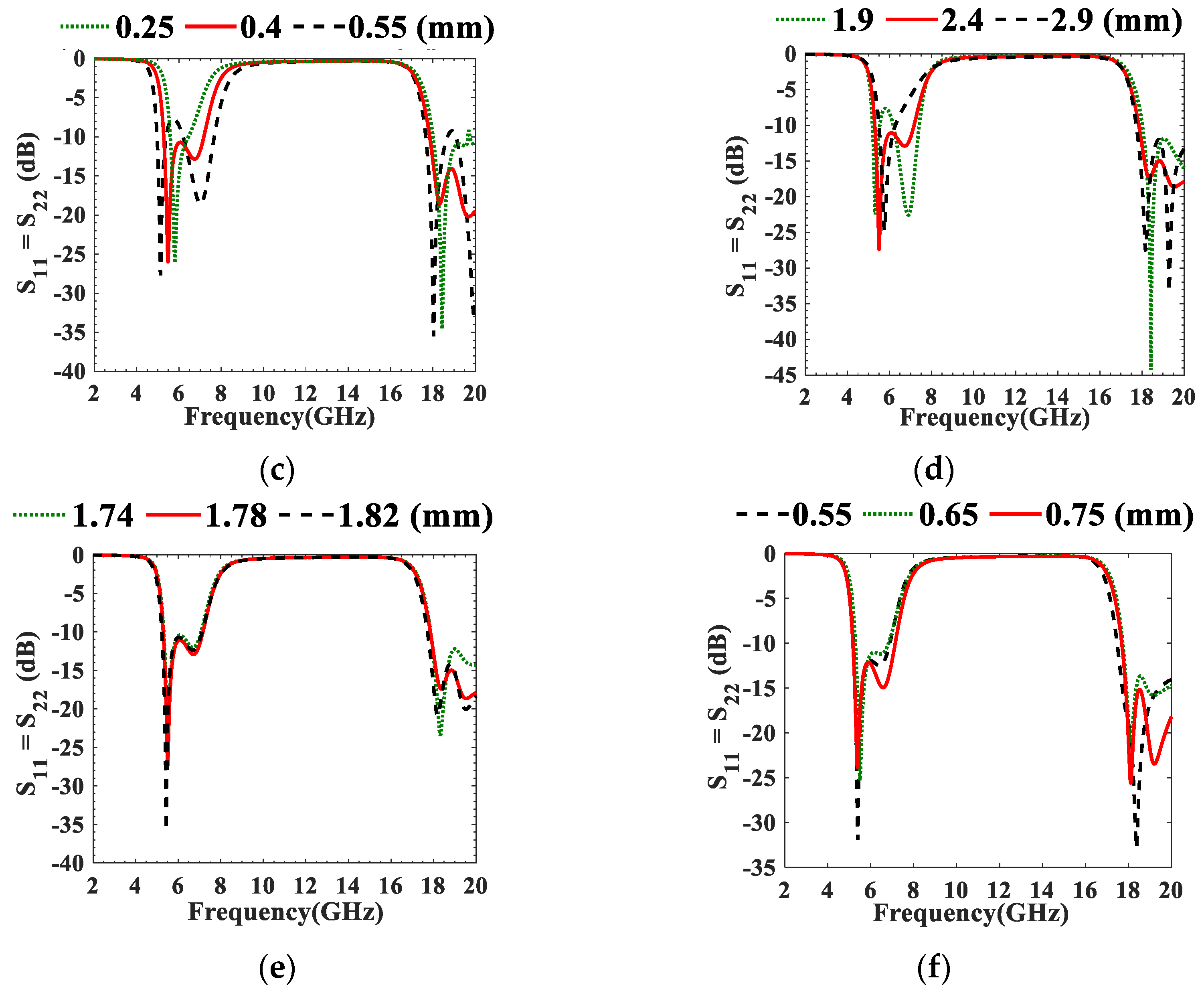
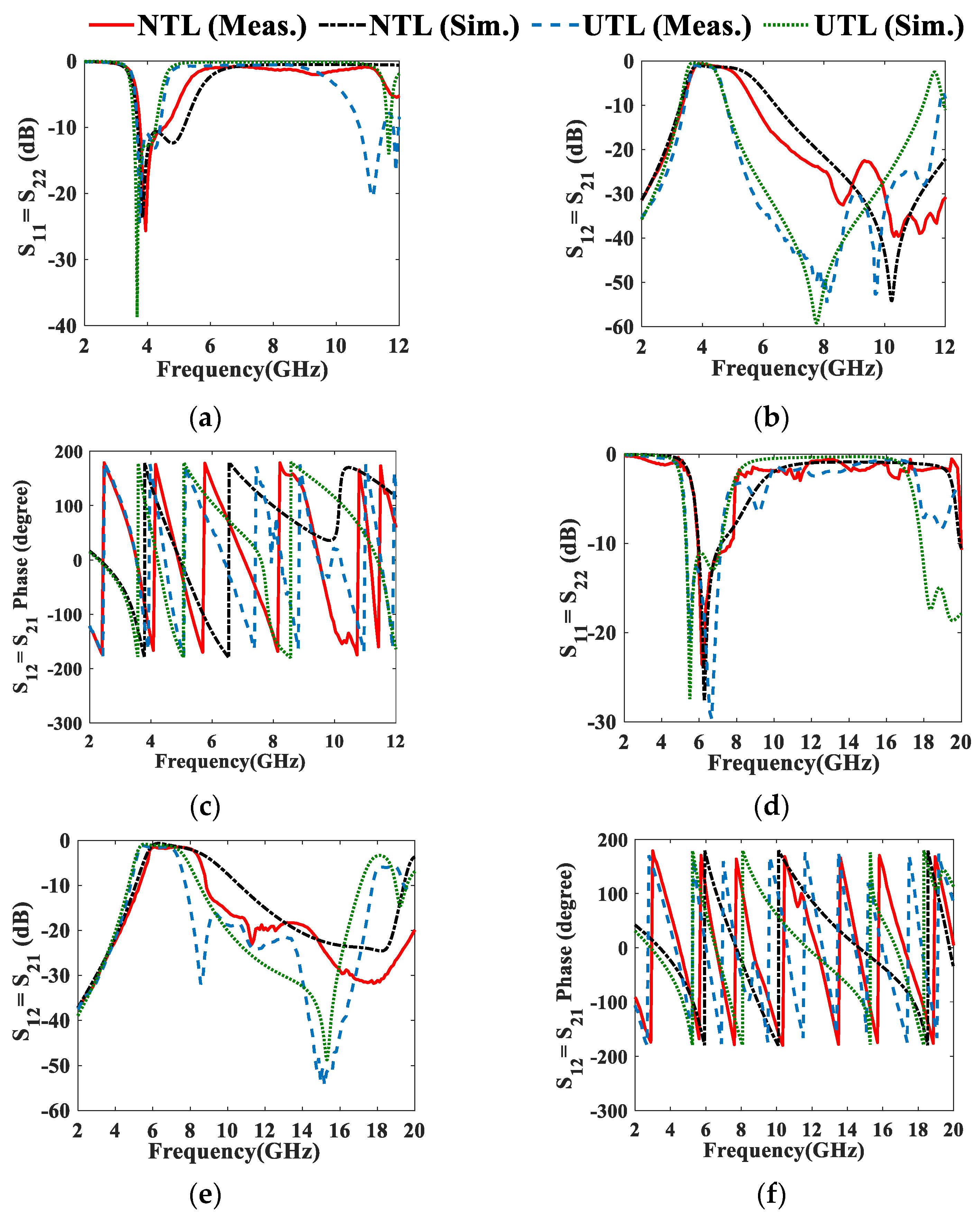
4. Result and Discussion
5. Conclusions
Author Contributions
Funding
Data Availability Statement
Conflicts of Interest
References
- Hong, J.-S.G.; Lancaster, M.J. Microstrip Filters for RF/Microwave Applications; John Wiley & Sons: Hoboken, NJ, USA, 2011; Volume 167, ISBN 0471464201. [Google Scholar]
- Saleh, S.; Ismail, W.; Zainal Abidin, I.S.; Jamaluddin, M.H. 5G Hairpin and Interdigital Bandpass Filters. Int. J. Integr. Eng. 2020, 12, 71–79. [Google Scholar] [CrossRef]
- Saleh, S.; Ismail, W.; Abidin, I.S.Z.; Jamaluddin, M.H.; Bataineh, M.H.; Alzoubi, A.S. 5G Hairpin Bandpass Filter. Jordanian J. Comput. Inf. Technol. 2021, 7, 1–12. [Google Scholar]
- Hariyadi, T.; Mulyasari, S.; Mukhidin. Design and Simulation of Microstrip Hairpin Bandpass Filter with Open Stub and Defected Ground Structure (DGS) at X-Band Frequency. IOP Conf. Ser. Mater. Sci. Eng. 2018, 306, 012124. [Google Scholar] [CrossRef]
- Naser-Moghadasi, M.; Alamolhoda, M.; Rahmati, B. Spurious Response Suppression in Hairpin Filter Using Dms Integrated in Filter Structure. Prog. Electromagn. Res. C 2011, 18, 221–229. [Google Scholar] [CrossRef] [Green Version]
- Ni, J. Development of Tunable and Miniature Microwave Filters for Modern Wireless Communications. Ph.D. Thesis, Heriot-Watt University, Edinburgh, Scotland, 2014. [Google Scholar]
- Abdullah, Q.; Mohd Shah, N.S.; Farah, N.; Jabbar, W.A.; Abdullah, N.; Salh, A.; Mukred, J.A.A. A Compact Size Microstrip Five Poles Hairpin Band-Pass Filter Using Three-Layers Structure for Ku-Band Satellites Application. Telkomnika 2020, 18, 80–89. [Google Scholar] [CrossRef]
- Tan, M.; Xuan, Y.; Ma, Y.; Li, L.; Zhuang, Y. Design of C-Band Interdigital Filter and Compact C-Band Hairpin Bandpass Film Filter on Thin Film Substrate. In RF and Microwave Microelectronics Packaging II; Springer: Cham, Switzerland, 2017; pp. 63–73. [Google Scholar]
- Saleh, S.; Ismail, W.; Zainal Abidin, I.S.; Jamaluddin, M.H.; Al-Gailani, S.A.; Bataineh, M.; Alzoubi, A. Size Reduction Percentage Study of 5 g Hairpin Bandpass Filter Nonuniform Transmission Line Resonator. In Proceedings of the 2019 IEEE Asia-Pacific Conference on Applied Electromagnetics (APACE), Malacca, Malaysia, 25–27 November 2019; pp. 1–5. [Google Scholar]
- Saleh, S.; Ismail, W.; Zainal Abidin, I.S.; Jamaluddin, M.H. Compact 5G Hairpin Bandpass Filter Using Non-Uniform Transmission Lines Theory. Appl. Comput. Electromagn. Soc. J. 2021, 36, 126–131. [Google Scholar] [CrossRef]
- Basavaraju, D.R.; Kumaraswamy, H.V.; Kothari, M.; Kamat, S. Interdigital Band Pass Filters for Duplexer Realization for LTE Band 28. In Proceedings of the 2017 International Conference on Intelligent Computing and Control (I2C2), Coimbatore, India, 23–24 June 2017; pp. 1–4. [Google Scholar]
- Divya Bharathi, R.; Evangeline Yamini, J.; Evangeline, A.; Badri Narayanan, D. Design and Analysis of Interdigital Microstrip Bandpass Filter for Centre Frequency 2.4 GHz. In Proceedings of the 3rd IEEE International Conference on Science Technology, Engineering and Management (ICONSTEM), Chennai, India, 23–24 March 2017; pp. 930–933. [Google Scholar]
- AtulMakrariya; Khare, P.K. Design and Analysis of a 5-Pole Interdigital BandPass Filter at 2.4 GHz. In Proceedings of the 2015 IEEE International Conference on Communication Networks (ICCN), Gwalior, India, 19–21 November 2015; pp. 93–96. [Google Scholar]
- Sharifi-tehrani, O. Design, Simulation and Fabrication of Microstrip Hairpin and Interdigital BPF for 2.25 GHz Unlicensed Band. Majlesi J. Telecommun. Devices 2017, 6, 115–118. [Google Scholar]
- Bo, Y.; Skafidas, E.; Evans, R. Design of Integrated Millimetre Wave Microstrip Interdigital Bandpass Filters on CMOS Technology. In Proceedings of the 37th European Microwave Conference (EUMC), Munich, Germany, 9–12 October 2007; pp. 680–683. [Google Scholar]
- Zhang, X.; Zhai, Q.; Li, Z.; Ou, W.; Ou, Y. Design of a K-Band Two-Layer Microstrip Interdigital Filter Exploiting Aggressive Space Mapping. J. Electromagn. Waves Appl. 2018, 32, 2281–2291. [Google Scholar] [CrossRef]
- Kurudere, S.; Ertürk, V.B. Novel SIW Based Interdigital Bandpass Filter with Harmonic Suppression. In Proceedings of the 44th European Microwave Conference (EUMC), Rome, Italy, 6–9 October 2014; pp. 845–848. [Google Scholar]
- Sahu, B.; Meshram, M.K.; Singh, S.P.; Tripathi, P. Design of Microstrip Interdigital Bandpass Filter with Suppression of Spurious Responses for L-Band Wireless Communication Applications. In Proceedings of the 2015 International Conference on Microwave and Photonics (ICMAP), Dhanbad, India, 11–13 December 2015; pp. 1–2. [Google Scholar]
- Ting, S.W.; Tam, K.W.; Martins, R.P. Novel Interdigital Microstrip Bandpass Filter with Improved Spurious Response. In Proceedings of the IEEE International Symposium on Circuits and Systems (IEEE CAT), Vancouver, BC, Canada, 23–26 May 2004; pp. 984–987. [Google Scholar]
- Ambak, Z.; Saad, M.R.; Alias, R.; Ibrahim, A.; Mohd Shapee, S.; Zulfadli, M.; Yusof, M.; Yahya, M.R. Design of Interdigital Band Pass Filter for WLAN Applications Using LTCC Technology. In Proceedings of the 2010 IEEE Asia-Pacific Conference on Applied Electromagnetics (APACE), Port Dickson, Malaysia, 9–11 November 2010; pp. 1–5. [Google Scholar]
- Cheng, J.; Alphones, A. Compact Interdigital Microstrip Band Pass Filter. Microw. Opt. Technol. Lett. 2010, 52, 2128–2132. [Google Scholar] [CrossRef]
- Hsieh, S.C.; Chang, C.C.; Chen, Y.M.; Lin, C.C.; Chang, S.F. Design of Ku-Band SIR Interdigital Bandpass Filter Using Silicon-Based Micromachining Technology. In Proceedings of the 10th Topical Meeting on Silicon Monolithic Integrated Circuits in RF Systems(SiRF), New Orleans, LA, USA, 11–13 January 2010; pp. 104–107. [Google Scholar]
- Hao, Z.; Hong, J.; Sciences, P.; Kingdom, U. Multilayer Interdigital Ultra-Wideband Filter. In Proceedings of the 2011 IEEE MTT-S International Microwave Symposium, Baltimore, MD, USA, 5–10 June 2011; pp. 4–7. [Google Scholar]
- Kao, H.L.; Cho, C.L.; Chang, L.C. Inkjet-Printed Interdigital Coupled Line Filter on Liquid Crystal Polymer Substrate. IEEE Electron Device Lett. 2013, 34, 1584–1586. [Google Scholar] [CrossRef]
- Chang, L.-C.; Cho, C.-L.; Bachani, S.K.; Kao, H.-L. Inkjet-Printed Interdigital Bandpass Filter with Wide Stopband Using Multilayer Liquid Crystal Polymer Technique. Int. J. Antennas Propag. 2018, 2018, 1–7. [Google Scholar] [CrossRef]
- Ge, J.J.; Jin, L. A Modified Interdigital Coupling Structure for Narrow Bandpass Filters Design. Electromagnetics 2015, 35, 550–556. [Google Scholar] [CrossRef]
- Lan, Y.; Xu, Y.; Wang, C.; Wen, Z.; Qiu, Y.; Mei, T.; Wu, Y.; Xu, R. X-Band Flexible Bandpass Filter Based on Ultra-Thin Liquid Crystal Polymer Substrate. Electron. Lett. 2015, 51, 345–347. [Google Scholar] [CrossRef]
- Yoon, K.; Kim, K. Compact Size of an Interdigital Band-Pass Filter with Flexible Bandwidth and Low Insertion-Loss Using a Folded Spiral and Stepped Impedance Resonant Structure. Electronics 2021, 10, 2003. [Google Scholar] [CrossRef]
- Ramanujam, P.; Ramanujam, K.; Ponnusamy, M. A Novel Asymmetrical Interdigital Coupled Line-based Penta-band Bandpass Filter Design with Enhanced Selectivity Employing Square Complementary Split Ring Resonator. Int. J. RF Microw. Comput.-Aided Eng. 2021, 31, e22888. [Google Scholar] [CrossRef]
- Wang, F.; Zhang, K.; Yin, X.; Yu, N.; Yang, Y. A Miniaturized Wideband Interdigital Bandpass Filter with High Out-Band Suppression Based on TSV Technology for W-Band Application. IEEE Trans. Very Large Scale Integr. VLSI Syst. 2022, 30, 989–992. [Google Scholar] [CrossRef]
- Liu, N.; Liu, X.; Liu, Y.; Yang, Y.; Zhu, Z. Compact Interdigital Bandpass Filter, Diplexer, and Triplexer Based on through Quartz Vias (TQVs). IEEE Trans. Compon Packag. Manuf. Technol. 2022, 12, 988–997. [Google Scholar] [CrossRef]
- Saleh, S.; Alzoubi, A.; Bataineh, M. Compact UWB Unequal Split Wilkinson Power Divider Using Nonuniform Transmission Lines. In Proceedings of the 2018 International Conference on Computer, Control, Electrical, and Electronics Engineering (ICCCEEE), Khartoum, Sudan, 12–14 August 2018; pp. 1–5. [Google Scholar]
- Saleh, S.; Ismail, W.; Zainal Abidin, I.S.; Jamaluddin, M.H.; Al-Gailani, S.A.; Alzoubi, A.S.; Bataineh, M.H. Nonuniform Compact Ultra-Wide Band Wilkinson Power Divider with Different Unequal Split Ratios. J. Electromagn. Waves Appl. 2020, 34, 154–167. [Google Scholar] [CrossRef]
- Saleh, S.; Ismail, W.; Zainal Abidin, I.S.; Jamaluddin, M.H.; Al-Gailani, S.A.; Alzoubi, A.S.; Bataineh, M.H. Compact UWB 1:2:1 Unequal-Split 3-Way Bagley Power Divider Using Non-Uniform Transmission Lines. J. Electromagn. Waves Appl. 2021, 35, 262–276. [Google Scholar] [CrossRef]
- 5G Spectrum Vision. White Paper; 5G Americas: Bellevue, WA, USA, 2019; pp. 1–50. [Google Scholar]
- Saleh, S.; Ismail, W.; Sorfina, I.; Abidin, Z.; Jamaluddin, H.; Bataineh, M.H.; Al-zoubi, A.S. Novel Compact UWB Vivaldi Nonuniform Slot Antenna with Enhanced Bandwidth. IEEE Trans. Antennas Propag. 2022, 70, 6592–6603. [Google Scholar] [CrossRef]
- Saleh, S.; Ismail, W.; Abidin, I.S.Z.; Jamaluddin, M.H.; Bataineh, M.H.; Alzoubi, A.S. Compact UWB Vivaldi Tapered Slot Antenna. Alex. Eng. J. 2022, 61, 4977–4994. [Google Scholar] [CrossRef]
- Abbas, A.; Hussain, N.; Sufian, M.A.; Jung, J.; Park, S.M.; Kim, N. Isolation and Gain Improvement of a Rectangular Notch Uwb-Mimo Antenna. Sensors 2022, 22, 1460. [Google Scholar] [CrossRef]
- Shabbir, T.; Saleem, R.; Al-Bawri, S.S.; Shafique, M.F.; Islam, M.T. Eight-Port Metamaterial Loaded UWB-MIMO Antenna System for 3D System-in-Package Applications. IEEE Access 2020, 8, 106982–106992. [Google Scholar] [CrossRef]
- Kissi, C.; Särestöniemi, M.; Kumpuniemi, T.; Myllymäki, S.; Sonkki, M.; Mäkelä, J.-P.; Srifi, M.N.; Jantunen, H.; Pomalaza-Raez, C. Receiving UWB Antenna for Wireless Capsule Endoscopy Communications. Prog. Electromagn. Res. C 2020, 101, 53–69. [Google Scholar] [CrossRef]
- Balderas, L.I.; Reyna, A.; Panduro, M.A.; del Rio, C.; Gutierrez, A.R. Low-Profile Conformal UWB Antenna for UAV Applications. IEEE Access 2019, 7, 127486–1274944. [Google Scholar] [CrossRef]
- Parameswari, S.; Chitra, C. Compact Textile UWB Antenna with Hexagonal for Biomedical Communication. J. Ambient Intell. Humaniz. Comput. 2021, 28, 1–8. [Google Scholar] [CrossRef]
- Kanagasabai, M.; Sambandam, P.; Alsath, M.G.N.; Palaniswamy, S.; Ravichandran, A.; Girinathan, C. Miniaturized Circularly Polarized UWB Antenna for Body Centric Communication. IEEE Trans. Antennas Propag. 2021, 70, 189–196. [Google Scholar] [CrossRef]
- Sufian, M.A.; Hussain, N.; Askari, H.; Park, S.G.; Shin, K.S.; Kim, N. Isolation Enhancement of a Metasurface-Based MIMO Antenna Using Slots and Shorting Pins. IEEE Access 2021, 9, 73533–73543. [Google Scholar] [CrossRef]
- Feng, Y.; Li, J.Y.; Zhang, L.K.; Yu, X.J.; Qi, Y.X.; Li, D.; Zhou, S.G. A Broadband Wide-Angle Scanning Linear Array Antenna With Suppressed Mutual Coupling for 5G Sub-6G Applications. IEEE Antennas Wirel. Propag. Lett. 2022, 21, 366–370. [Google Scholar] [CrossRef]
- Tang, X.; Chen, H.; Yu, B.; Che, W.; Xue, Q. Bandwidth Enhancement of a Compact Dual-Polarized Antenna for Sub-6G 5G CPE. IEEE Antennas Wirel. Propag. Lett. 2022, 21, 2015–2019. [Google Scholar] [CrossRef]
- Wang, S.; Hao, H.; Ma, X.; Cheng, H.; Huang, X. Wideband Circularly Polarized Array Antenna Based on Sequential Phase Feeding Metasurfaces for 5G (Sub-6G) Applications. J. Electromagn. Waves Appl. 2022. [Google Scholar] [CrossRef]
- Saleh, S.; Ismail, W.; Abidin, I.S.Z.; Jamaluddin, M.H.; Bataineh, M.; Alzoubi, A. Compact Reconfigurable Ultra Wide Band and 5G Narrow Band Vivaldi Tapered Slot Antenna. In Proceedings of the 2020 IEEE International RF and Microwave Conference (RFM), Kuala Lumpur, Malaysia, 14–16 December 2020; pp. 157–160. [Google Scholar]
- Potti, D.S.; Balaji, P.; Gulam Nabi Alsath, M.; Savarimuthu, K.; Selvam, U.; Valavan, N. Reconfigurable Bow Tie-Based Filtering Antenna for Cognitive Radio Applications. Int. J. RF Microw. Comput.-Aided Eng. 2020, 30, 1–10. [Google Scholar] [CrossRef]
- Niture, D.V.; Mahajan, S.P. A Compact Reconfigurable Antenna for UWB and Cognitive Radio Applications. Wirel. Pers. Commun. 2022, 125, 3661–3679. [Google Scholar] [CrossRef]
- Deng, J.; Hou, S.; Zhao, L.; Guo, L. A Reconfigurable Filtering Antenna with Integrated Bandpass Filters for UWB/WLAN Applications. IEEE Trans. Antennas Propag. 2017, 66, 401–404. [Google Scholar] [CrossRef]
- Kantemur, A.; Abdelrahman, A.H.; Xin, H. A Novel Compact Reconfigurable UWB Antenna for Cognitive Radio Applications. In Proceedings of the 2017 IEEE Antennas and Propagation Society International Symposium, San Diego, CA, USA, 9–14 July 2017; pp. 1369–1370. [Google Scholar]
- Khalaj-Amirhosseini, M. Wideband or Multiband Complex Impedance Matching Using Microstrip Nonuniform Transmission Lines. Prog. Electromagn. Res. 2006, 66, 15–25. [Google Scholar] [CrossRef]


| Parameters | 3.95 GHz UTLIBF | 6.55 GHz UTLIBF | ||
|---|---|---|---|---|
| Calculated | Optimized | Calculated | Optimized | |
| k12= k23 | 0.091 | - | 0.127 | - |
| Lres1 (mm) | 11.58 | 10.3 | 7.0382 | 6.23 |
| Lres2 (mm) | 11.38 | 10.1 | 6.81 | 6 |
| Wres (mm) | 1.843 | 1.95 | 2.245 | 2.3 |
| S (mm) | 0.95 | 0.8 | 0.55 | 0.4 |
| Lt (mm) | 2.332 | 2.75 | 1.9 | 2.4 |
| rVia (mm) | - | 0.425 | - | 0.75 |
| Lp1 (mm) | - | 3.5 | - | 3 |
| Lp2 (mm) | - | 5.5 | 3.5 | |
| Wp (mm) | 1.819 | 1.819 | 1.819 | 1.78 |
| at (3.7–4.2 GHz) | ||||||
|---|---|---|---|---|---|---|
| C0 | C1 | C2 | C3 | C4 | C5 | |
| 1st | 0.2896 | 0.3420 | −0.0105 | −0.1674 | −0.1339 | −0.0670 |
| 2nd | 0.0602 | 0.0825 | 0.0496 | 0.0130 | −0.0038 | −0.0188 |
| C6 | C7 | C8 | C9 | C10 | ||
| 1st | −0.0299 | −0.0282 | −0.0636 | −0.0848 | −0.0462 | |
| 2nd | −0.0335 | −0.0514 | −0.0493 | −0.0342 | −0.0143 | |
| at (5.975–7.125 GHz) | ||||||
| C0 | C1 | C2 | C3 | C4 | C5 | |
| 1st | 0.0043 | 0.0007 | −0.0002 | 0.0004 | 0.0004 | −0.0003 |
| 2nd | 0.0222 | 0.0180 | −0.0028 | 0.0026 | 0.0018 | −0.0188 |
| C6 | C7 | C8 | C9 | C10 | ||
| 1st | −0.0004 | −0.0001 | −0.0003 | −0.0009 | −0.0011 | |
| 2nd | −0.0054 | −0.0016 | −0.0056 | −0.0140 | −0.0095 | |
| Parameters | Sim. | Meas. | Sim. | Meas. |
|---|---|---|---|---|
| at (3.7–4.2 GHz) | at (5.975–7.125 GHz) | |||
| S11 = S22 (NTL) | <−10.63 dB.at 3.7–5.15 GHz, H.S up to 11.8 GHz | <−11.2 dB.at 3.7–4.25 GHz, H.S up to 11.25 GHz | <−10.45 dB.at 5.93–7.39 GHz H.S up to 18 GHz | <−11.27 dB at 5.94–7.67 GHz, H.S up to 20 GHz |
| S11 = S22 (UTL) | <−11.84 dB at 3.57–4.24 GHz, H.S up to 11.8 GHz | <−10.63 dB at 3.66–4.4 GHz, H.S up to 11.12 GHz | <−11.05dB at 5.3–7.164 GHz, H.S up to 18 GHz | <−13.91 dB at 5.34–7.163 GHz, H.S up to 20 GHz |
| S12 = S21 (NTL) | −1.34 dB at FC = 4.43 GHz | −0.86 dB at FC = 3.98 GHz | −0.8 dB at FC = 6.68 GHz | −1.7 dB at FC = 6.81 GHz |
| S12 = S21 (UTL) | −0.64 dB at FC = 3.91 GHz | −1.26 dB at FC = 4.03 GHz | −1.09 dB at FC = 6.25 GHz | −1.78 dB at FC = 6.25 GHz |
| Ref., Layers Order | h (mm)/εr | Technique | 3dB FBW, Frequency Band (GHz) | S11 (dB) | S12 (dB) | H.S Up to GHz | Area mm2, λg2 |
|---|---|---|---|---|---|---|---|
| This work 3rd | 0.813/3.55 | NTLs | 13.82%, 3.7–4.25 | −10.52 | −0.86 | 11.25 | 16.7 × 9.83, 0.32 × 0.21 |
| 25.40%, 5.94–7.67 | −11.27 | −1.7 | 18 | 13.9 × 7.02, 0.51 × 0.26 | |||
| [31], 1, 3rd | IPDs | TQVs | 9.42%, 27.2–29.89 | −15.17 | −1.66 | 74 | 1.715 × 7.6, 0.15 × 0.15 |
| [30], 1, 7th | IPDs | TSV | 58.89%, 61.97–113.7 | −20 | −1.3 | 87 | 0.5 × 0.34, 0.48 × 0.33 |
| [28], 1, 3rd | 0.54/2.54 | spiral and folded SIR | 180%, 0.2–1.42 | −17.1 | −0.043 | NA | 13.8 × 5.98, 0.05 × 0.02 |
| [16],2, 6th | 0.40/11.9 | MEMS technology | 7.8%, 19.6–21.2 | −15 | −1.98 | NA | 7 × 3, 1.34 × 0.57 |
| [25], 4, 2nd | 0.0034/2.9 | Inject printing on LCPT | 17%, 10.52–12.48 | −12 | −2.2 | NA | 5.28 × 3.32, 0.32 × 0.2 |
| [8], 1, 4th | 0.381/9.8 | High εr substrate | 15%, 7.4–8.6 | −20 | −1.5 | NA | 5 × 5, 0.34 × 0.34 |
| [26], 1, 5th | 0.508/3.66 | λ/4 and λ/2 resonators | 4.5%, 9.85–10.3 | −14.68 | −4.56 | NA | 28.30 × 10.63, 1.51 × 0.60 |
| [18],1, 5th | 1.27/10.2 | Spurlines | 64%, 0.99–1.96 | −10.93 | −0.83 | 8 | 15.5 × 22, 0.24 × 0.35 |
| [27], 1, 2nd | 0.05/3 | Ultra-thin LCP | 8.19%, 9–9.77 | −22 | −2.3 | NA | 5.4 × 3.2, 0.16 × 0.26 |
Publisher’s Note: MDPI stays neutral with regard to jurisdictional claims in published maps and institutional affiliations. |
© 2022 by the authors. Licensee MDPI, Basel, Switzerland. This article is an open access article distributed under the terms and conditions of the Creative Commons Attribution (CC BY) license (https://creativecommons.org/licenses/by/4.0/).
Share and Cite
Saleh, S.; Jamaluddin, M.H.; Razzaz, F.; Saeed, S.M. Compact 5G Nonuniform Transmission Line Interdigital Bandpass Filter for 5G/UWB Reconfigurable Antenna. Micromachines 2022, 13, 2013. https://doi.org/10.3390/mi13112013
Saleh S, Jamaluddin MH, Razzaz F, Saeed SM. Compact 5G Nonuniform Transmission Line Interdigital Bandpass Filter for 5G/UWB Reconfigurable Antenna. Micromachines. 2022; 13(11):2013. https://doi.org/10.3390/mi13112013
Chicago/Turabian StyleSaleh, Sahar, Mohd Haizal Jamaluddin, Faroq Razzaz, and Saud M. Saeed. 2022. "Compact 5G Nonuniform Transmission Line Interdigital Bandpass Filter for 5G/UWB Reconfigurable Antenna" Micromachines 13, no. 11: 2013. https://doi.org/10.3390/mi13112013