Article

Effects of Moisture Diffusion on a System-in-Package Module by Moisture–Thermal–Mechanical-Coupled Finite Element Modeling

1
The Institute of Technological Science, Wuhan University, Wuhan 430072, China
2
Tsinghua Innovation Center in Zhuhai, Zhuhai 519080, China
3
School of Materials Science and Engineering, Wuhan University of Technology, Wuhan 430070, China
*
Author to whom correspondence should be addressed.
Micromachines 2022, 13(10), 1704; https://doi.org/10.3390/mi13101704
Submission received: 28 July 2022 / Revised: 23 September 2022 / Accepted: 5 October 2022 / Published: 10 October 2022
(This article belongs to the Special Issue Advanced Packaging for Microsystem Applications)

Abstract

:
Epoxy molding compounds (EMCs) are commonly used in electronic products for chip encapsulation, but the moisture absorption of EMC can induce significant reliability challenges. In this study, the effects of hygrothermal conditions and structure parameters on moisture diffusion and the consequent influences (such as moisture content on die surfaces and stress distribution) on a system-in-package module have been systematically investigated by moisture–thermal–mechanical-coupled modeling. Hygroscopic tests were carried out on a new commercial EMC at 60 °C/60% RH and 85 °C/85% RH, followed by evaluations of diffusion coefficients by Fick’s law. It was found that the moisture diffusion coefficients and saturation concentrations at 85 °C/85% RH were higher than those at 60 °C/60% RH. From the modeling, it was found that the consequent maximum out-of-plane deformation and stress of the module at 85 °C/85% RH were both higher than those at 60 °C/60% RH. Influences of thicknesses of EMC and PCB on the moisture diffusion behavior have also been studied for design optimization. It was found that the maximum moisture concentration on die surfaces and resultant stress increased notably with thinner PCB, whereas the effects of EMC thickness were limited. This can be attributed to the comparison between the thicknesses of EMC and PCB and the shortest existing diffusion path within the module. These findings can provide helpful insights to the design optimization of electronic modules for hygrothermal conditions.

1. Introduction

Epoxy molding compounds (EMCs) are widely used in consumer products to protect encapsulated devices. However, a notable side effect of EMCs is the moisture absorption from the air until saturation. This can pose serious threats to the performance and reliability of a device due to potential “pop-corning” failure, swelling, electrochemical migration, and interfacial degradation [1,2,3].
In the literature, various methodologies were reported to characterize the effects of moisture absorption on the mechanical performance of bulk EMC and EMC/substrate interfaces, such as piezoresistive stress sensor chips for strain measurements [4], and micro-digital image speckle correlation (μ-DiSC) for interfacial fracture toughness [5]. Finite element modeling and molecular dynamics were also frequently used to study the influences of moisture absorption on the device reliability [6,7,8,9,10,11]. It was found that the interactions between water molecules and the chain structure of epoxy polymer during moisture diffusion can alter the mechanical and thermal performance of EMCs [7,12,13]. However, the majority of recent studies have focused on the diffusion behavior of moisture [12,13,14,15,16]. The interactions between electronic modules and moisture diffusion have seldom been studied, such as resultant stress distribution by moisture diffusion, and the effects of structure parameters of an electronic module on moisture diffusion.
In this study, a new commercial EMC was studied for hygroscopicity under different conditions: 85 °C/85% RH and 60 °C/60% RH. After hygroscopic tests, a moisture–thermal–mechanical-coupled model was built for a system-in-package module to investigate the effects of hygrothermal conditions on the moisture and stress distribution. Influences of major structure parameters of the module on the stress and moisture distribution were also studied, such as the thickness of the EMC and the printed circuit board (PCB).

2. Materials and Methods

EMC strips with of 30 mm × 8 mm × 0.8 mm (length × width × thickness) in size were prepared for hygroscopic tests. According to JEDEC J-STD-020E [17], the samples were baked in an oven at 125 °C for 24 h to minimize the effects of residual moisture and obtain the dry weights before tests. Subsequently, the samples were tested in a temperature and humidity chamber (CHTH4005, temperature range: −40 °C–150 °C, humidity range: 10–98% RH) at two different hygrothermal conditions: 85 °C/85% RH and 60 °C/60% RH for 50 h (Figure 1). Five samples were tested for each condition to obtain more reliable results. Samples were weighed with a high-precision electronic balance (accuracy 0.1 mg) before hygroscopic tests, and every 4 h after the tests started.
To further elucidate the effects of moisture absorption on the reliability of electronic modules, a finite element model for a system-in-package module was built, as shown in Figure 2. Diffusion coefficients and saturation concentrations of EMCs were obtained from hygroscopic tests. Other parameters were provided by the vendor or from the literature, as listed in Table 1.
Based on the model in Figure 2, the bottom center of PCB was fixed with no other mechanical constraints. The transport of diluted species module in Comsol was used to simulate the moisture diffusion behavior [22]. Moisture diffusion within both EMC and PCB was included in the model with compliance to Fick’s law. Two sets of hygrothermal loads were applied in modeling: 85 °C/85% RH and 60 °C/60% RH for 168 h (case 1 and case 2 in Table 2, respectively). To simulate the effects of moisture diffusion on an electronic module, two other physical modules (such as solid mechanics and heat transfer) and the corresponding coupling modules (such as thermal expansion and hygroscopic swelling) were utilized to investigate the coupling effects of temperature, moisture, and solid mechanics under hygrothermal conditions. The governing theories of these phenomena in modeling can be expressed as follows [22]:
(1)
Theory for heat transfer:
ρ C p ( T t + u trans · T ) + · ( q + q r ) = α T : dS dt + Q
where ρ is the density, Cp is the specific heat capacity at constant stress, T is the absolute temperature, utrans is the velocity vector of translational motion, q is the heat flux by conduction, qr is the heat flux by radiation, α is the coefficient of thermal expansion, S is the second Piola–Kirchhoff stress tensor, and Q contains additional heat sources.
(2)
Theory for the transport of diluted species by Fick’s law approximation:
j md , i = ρ i D i , kl F x i x i
where jmd,i is the diffusive flux, ρi is the density, xi is the mole fraction of species i, and D i , k l F represents a general diffusion matrix.
(3)
Theory for structural mechanics:
σ = C : ε
where σ is the stress tensor, ε is the strain tensor, and C is the constitutive tensor.
(4)
Theory for thermal expansion:
ε th = α ( T T ref )
where εth is the strain by thermal expansion, α is the coefficient of thermal expansion, and T and Tref are the current temperature and reference temperature, respectively.
(5)
Theory for hygroscopic swelling:
ε hs = β h M m ( c mo c mo , ref )
where βh is the coefficient of hygroscopic swelling, Mm is the molar mass, cmo is the moisture concentration, and cmo,ref is the strain-free reference concentration.
Some hypotheses were also included to simplify the modeling: (1) after baking at 125 °C for 24 h, the moisture in EMC was assumed to be ideally removed; and (2) both PCB and EMC were assumed to be isotropic and elastic in thermal expansion and hygroscopic swelling.
To elucidate the different effects of thermal expansion and hygroscopic swelling on the stress distribution in the module, the same model was then studied at 85 °C/85% RH with only thermal expansion or hygroscopic swelling for comparison (case 3 and case 4 in Table 2). To further study the influences of structure parameters, models with different EMC thicknesses (2.7~3.7 mm) and PCB thicknesses (0.7~1.7 mm) were then investigated for the comparisons of maximum moisture concentration and stress at IC chips (case 5 and case 6 in Table 2).

3. Results

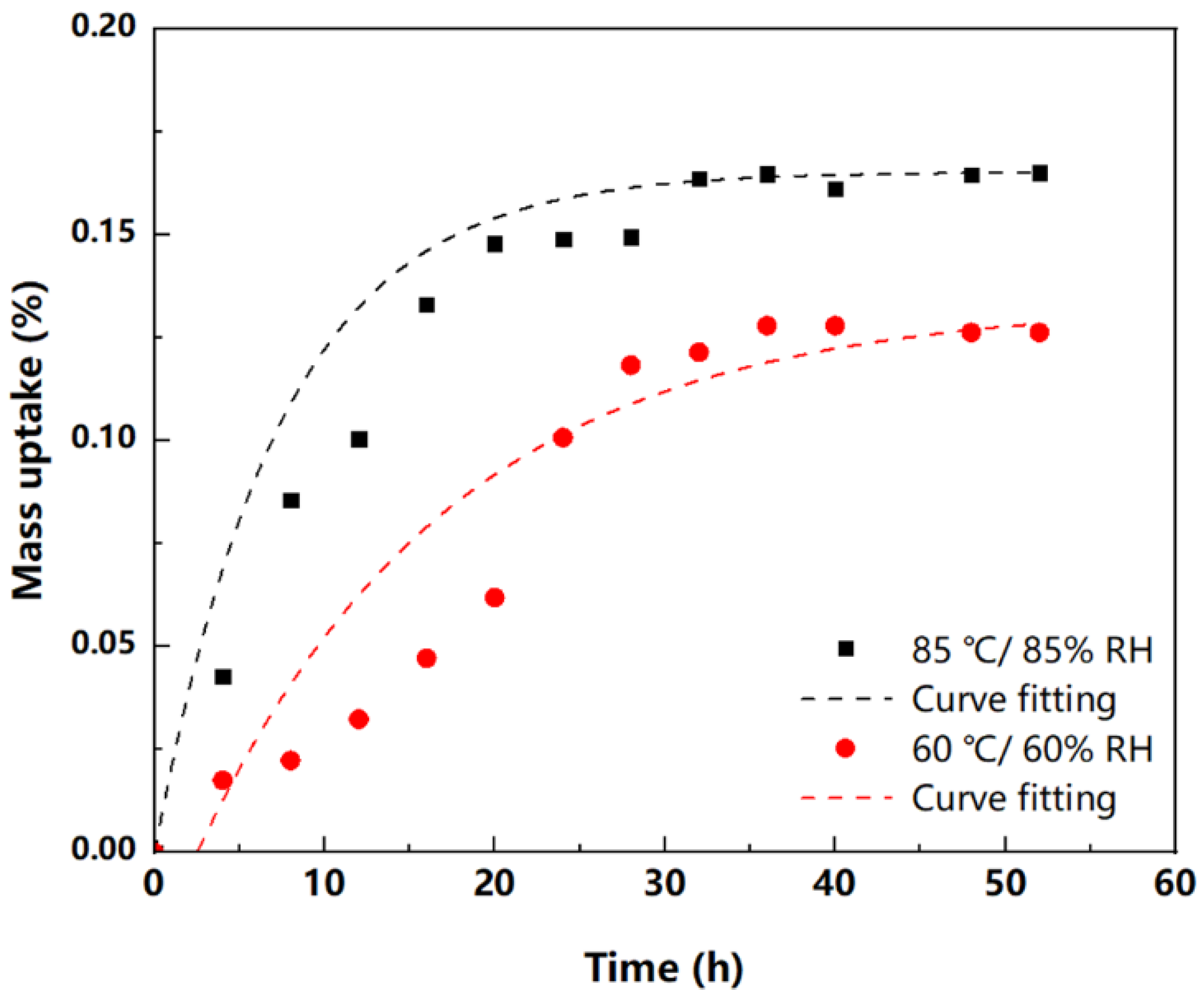
3.1. Hygroscopicity of EMC

Figure 3 shows the average mass increases in EMC at 85 °C/85% RH and 60 °C/60% RH. For both conditions, the weight increases were faster at the beginning of tests, but generally stabilized when the tests lasted for longer than 35 h. Although different diffusion models have been proposed for moisture diffusion [23,24,25,26], Fick’s law is still the most common theory used for data analysis [12,27], which was also employed in our study.
For homogeneous materials, Fick’s law can be expressed as:
C t = D ( 2 C x 2 + 2 C y 2 + 2 C z 2 )
where D (mm2/s) is the diffusion coefficient and C (g/mm3) is the moisture concentration. For one-dimensional cases, the sample weight can be expressed as a function of time:
M t M = 1 8 π 2 n = 0 1 ( 2 n + 1 ) 2 exp ( D ( 2 n + 1 ) 2 π 2 4 l 2 t )
where Mt is the sample weight at time t, M is the weight after saturation, and l is the thickness of the sample.
Based on curve fitting with Equation (7), the diffusion coefficients at 85 °C/85% RH and 60 °C/60% RH can be evaluated. The relatively higher deviation between 10 h and 20 h in Figure 3 can be attributed to the relatively lower absolute weight of absorbed moisture in the initial stage of tests. Moreover, the saturation concentration of moisture within EMCs can also be estimated by C s a t = M V . Therefore, major moisture diffusion parameters of this new commercial EMC are listed in Table 3. In the literature, it has been reported that the diffusion coefficients for most molding compounds at 85 °C ranged from 2 × 10⁻¹³ m2/s to 6 × 10⁻¹³ m2/s [28,29,30]. The moisture diffusion coefficient of this new EMC is close to the lower bounds of reported results.

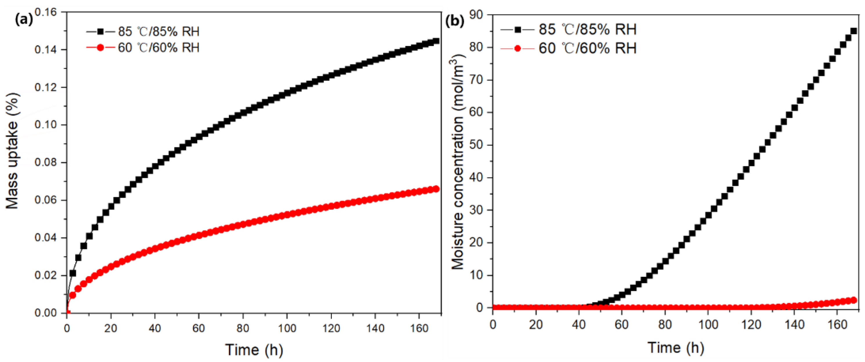
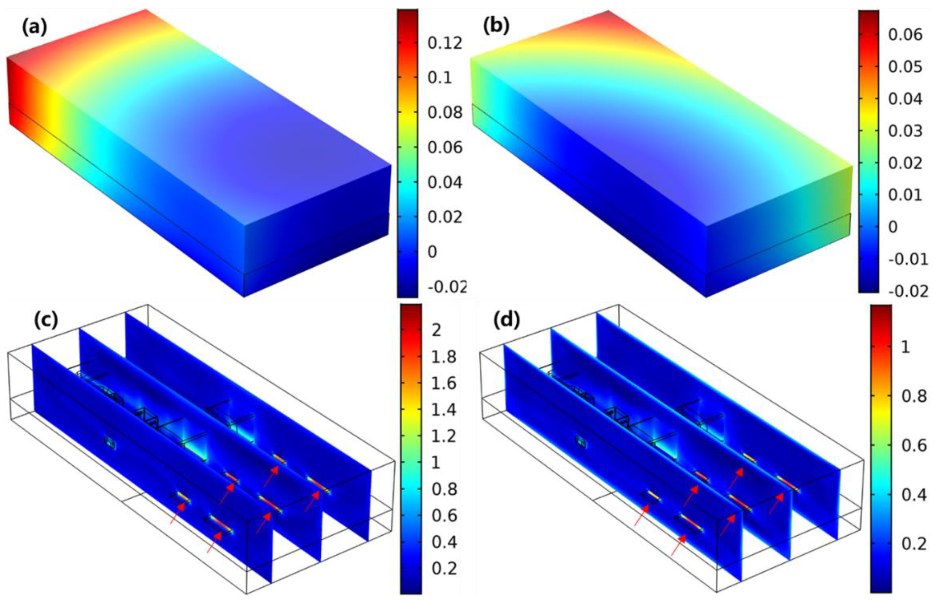
3.2. Influences of Hygrothermal Conditions

To elucidate the effects of moisture absorption on electronic modules, a moisture–thermal–mechanical-coupled model was built for a system-in-package module under different conditions: 60 °C/60% RH and 85 °C/ 85% RH. Figure 4a shows that the mass uptake within the module at 85 °C/85% RH and 60 °C/60% RH generally conformed with Fick’s law, but the rate at the former was evidently higher than that at the latter. This also shows that the moisture absorption did not even reach an equilibrium state after 168 h, which can be attributed to the high volume of EMC in this module. Figure 4b illustrates the comparison of maximum moisture concentrations on die surfaces under different conditions. This shows that moisture concentrations on die surfaces remained close to 0 mol/m3 in the initial 40 h of diffusion. Subsequently, the increase in moisture concentration at 85 °C/85% RH was much faster than that at 60 °C/60% RH. The final content at 85 °C/85% RH was also approximately 34.6 times higher than that at 60 °C/60% RH.
Figure 5a,b show the comparison of out-of-plane deformation within the module after subjected to 85 °C/85% RH and 60 °C/60% RH for 168 h. It can be found that the warpage at 85 °C/85% RH (0.14 mm) was more severe than that at 60 °C/60% RH (0.07 mm). In addition, the shape at 85 °C/85% RH was slightly different from that at 60 °C/60% RH with different locations of minimum deformation along the Z axis. Figure 5c,d illustrate the stress distribution within the module. It is shown that the stress was generally concentrated at the chips, and the maximum stress at 85 °C/85% RH (219 MPa) was much higher than that at 60 °C/60% RH (117 MPa).
To compare the contributions of temperature and moisture with stress distribution within the electronic module, the models were then built with only thermal expansion or hygroscopic swelling at 85 °C/85% RH (case 3 and case 4 in Table 2). Figure 6a,b show the comparison of influences of hygroscopic swelling and mismatch of CTE on stress distribution within the module. This shows that the stress by moisture absorption was generally concentrated at both the chips and the Al leads of the TO package (as illustrated in Figure 6a). However, the maximum stress induced by the mismatch of CTE was located at the chips (Figure 6b). Both EMC and PCB were capable of absorbing moisture under hygrothermal conditions, but the moisture diffusion within Si and Al was negligible, as detailed in Table 1. This led to the mismatch of hygroscopic swelling and consequent stress concentration within both Si chips and Al leads, as depicted in Figure 6a. The stress concentration at IC chips shown in Figure 6b can be attributed to its lower thermal expansion in comparison with EMC and PCB. From Table 1, the CTE of EMC is 5.6 times higher than that of IC chips, but those of EMC, PCB, and Al are much closer to each other. Therefore, the stress by CTE mismatch was generally concentrated at the chips (Figure 6b).

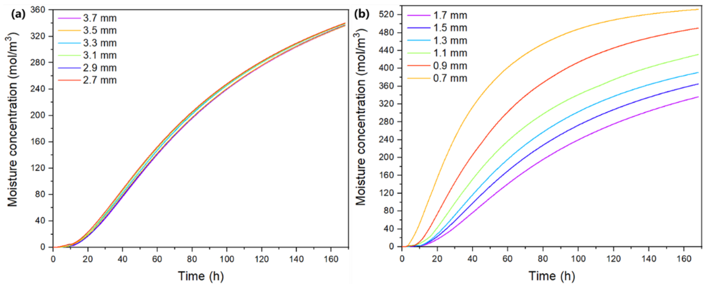
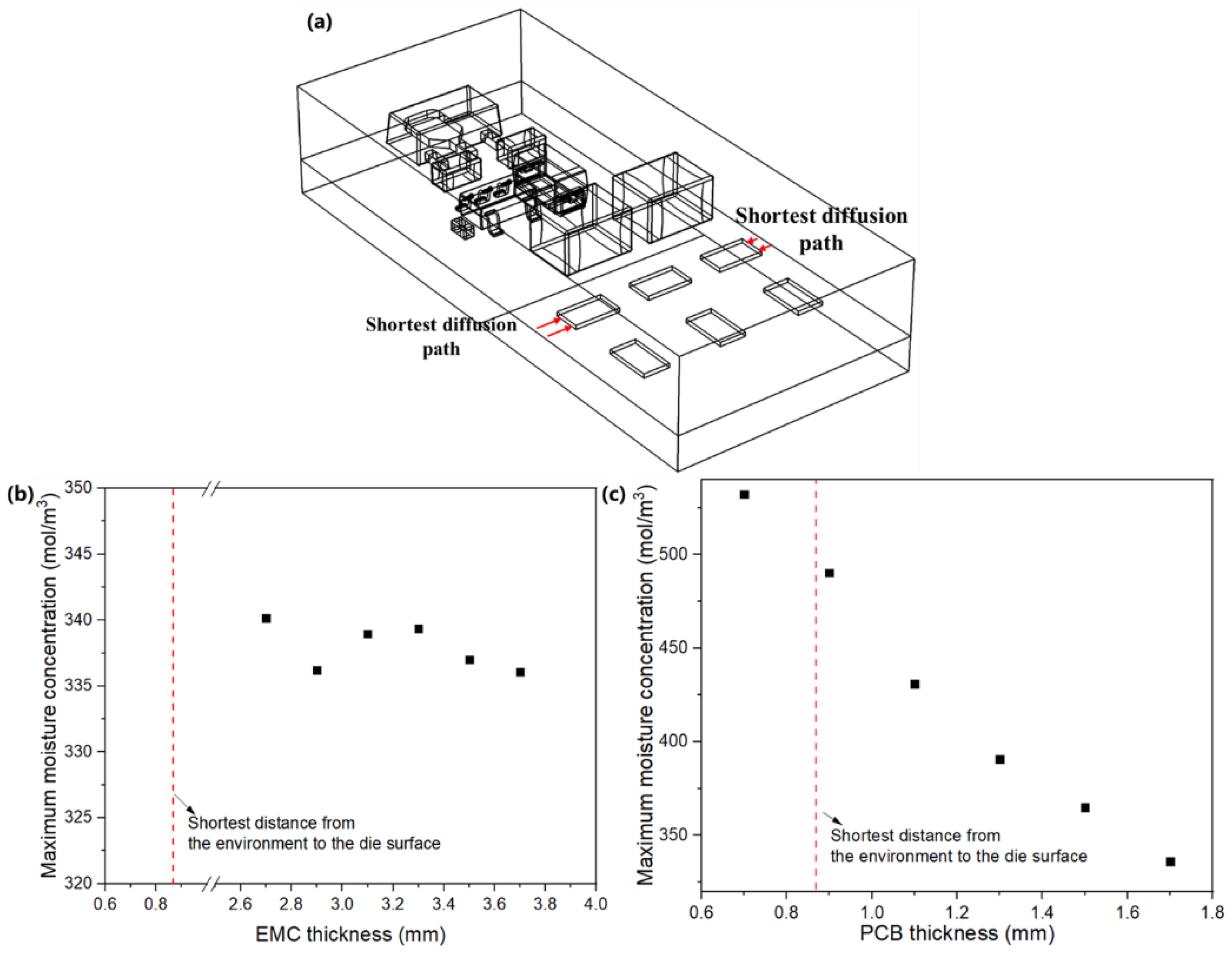
3.3. Effects of Structure Parameters

Figure 7 illustrates the effects of PCB thickness and EMC thickness on the maximum moisture concentration on the die surfaces in the module at 85 °C/85% RH. It shows that maximum moisture concentration on die surfaces generally increased with a thinner PCB or EMC. When the EMC thickness dropped from 3.7 mm to 2.7 mm, the maximum moisture concentration on die surfaces increased from 336.1 mol/m3 to 340.1 mol/m3. In contrast, the effects of PCB thickness are more significant. When the PCB thickness decreased by 1 mm, the highest moisture concentration on die surfaces reached about 1.6-fold higher than the initial value, from 336.1 mol/m3 to 532.3 mol/m3. This implies that the moisture concentration within this module is more sensitive to PCB thickness than EMC thickness.
These changes can be attributed to the comparison of EMC and PCB thicknesses with the shortest existing diffusion path (Figure 8). In the original model (case 1), the shortest diffusion path was from the side surfaces to chips, about 0.87 mm (Figure 8a). In modeling, the investigated EMC thicknesses were far greater than the shortest existing diffusion path due to the capacitors. Therefore, reducing EMC thickness can only pose a minimal effect on the maximum moisture content on die surfaces (Figure 8b). In contrast, the investigated PCB thicknesses are close to the shortest existing diffusion distance; thus, reducing the PCB thickness can significantly enhance the moisture diffusion into the module through PCB. Hence, the maximum moisture content on die surfaces increased significantly with the thinner PCB (Figure 8c).
Figure 9 demonstrates the comparison of influences of EMC thickness and PCB thickness on maximum stress within silicon chips under 85 °C/85% RH. This shows that the maximum stress generally decreased linearly with a thicker EMC or PCB. Curve fitting yielded σ = 403.1-21.4d for EMC thickness and σ = 457.6-64.5d for PCB thickness, where σ is the maximum stress in chips (MPa) and d is the thickness (mm). The negative correlation between maximum stress and thicknesses of EMC and PCB can be attributed to smaller amounts of absorbed moisture and less consequent swelling mismatch if the thickness increases. The maximum stress is more sensitive to PCB thickness (Figure 9b) because it is at a comparable level to the shortest existing diffusion path.
Consequently, in module design, optimizing structural parameters (such as EMC thickness and PCB thickness) can be used to improve the stress distribution and moisture concentration on die surfaces when subjected to hygrothermal conditions. It is also essential to take the influences of the shortest existing diffusion path into account.

4. Conclusions

In this study, the moisture absorption behavior of a new commercial EMC was evaluated by hygroscopic tests. The effects of hygrothermal conditions and structure parameters on the stress were studied, as was moisture distribution within a system-in-package module. Based on the presented results and discussions, the following conclusions can be drawn:
  • The moisture diffusion coefficient and saturation content of the new EMC at 85 °C/85% RH was higher than the values at 60 °C/60% RH;
  • For the studied module, both the maximum out-of-plane deformation and maximum stress at 85 °C/85% RH were higher than the values at 60 °C/60% RH;
  • When subjected to hygrothermal condition, the stress caused by hygroscopic swelling generally concentrated at the chips and Al leads, but the maximum stress by CTE mismatch was located at the chips;
  • Structure parameters can pose significant effect on the distribution of stress and moisture within electronic modules under hygrothermal conditions, which is particularly true when the structure parameters are close to the shortest existing diffusion path.
In future, we will further investigate the combined effects of hygrothermal conditions, moisture diffusivity, shortest diffusion path, and structure parameters on moisture diffusion behaviors. Therefore, more generalized guidelines can be derived for design optimization.

Author Contributions

Conceptualization, Z.C.; methodology, Z.C.; software, Z.C.; formal analysis, Z.F.; investigation, Z.F. and M.R.; resources, L.L.; data curation, G.X.; writing—original draft preparation, Z.C.; writing—review and editing, Z.C.; visualization, G.X.; supervision, L.L.; project administration, L.L.; funding acquisition, Z.C. and L.L. All authors have read and agreed to the published version of the manuscript.

Funding

This study was funded by the National Key R&D Program of China, grant number 2019YFB1704600; the National Natural Science Foundation of China, grant number 61904127 and 62004144; Guangdong Basic and Applied Basic Research Foundation, grant number 2021A1515010651; Fundamental Research Funds for the Central Universities, grant number 213201006 and 213134005; Hubei Provincial Natural Science Foundation of China, grant number 2020CFA032.

Data Availability Statement

Not applicable.

Conflicts of Interest

The authors declare no conflict of interest.

References

  1. Fan, X.J.; Lee, S.W.R.; Han, Q. Experimental investigations and model study of moisture behaviors in polymeric materials. Microelectron. Reliab. 2009, 49, 861–871. [Google Scholar] [CrossRef]
  2. Fu, S.-W.; Lee, C.C. A corrosion study of Ag–Al intermetallic compounds in chlorine-containing epoxy molding compounds. J. Mater. Sci. Mater. Electron. 2017, 28, 15739–15747. [Google Scholar] [CrossRef] [Green Version]
  3. Chen, Y.; Li, P. The “popcorn effect” of plastic encapsulated microelectronic devices and the typical cases study. In Proceedings of the 2011 International Conference on Quality, Reliability, Risk, Maintenance, and Safety Engineering, Xi’an, China, 17–19 June 2011; pp. 482–485. [Google Scholar]
  4. Xin, D. Mechanical properties and the interface failure mechanism of epoxy resin under hygrothermal condition. In School of Civil Engineering and Transportation; South China University of Technology: Guangzhou, China, 2013. [Google Scholar]
  5. Shi, X.Q.; Zhang, Y.L.; Zhou, W.; Fan, X.J. Effect of Hygrothermal Aging on Interfacial Reliability of Silicon/Underfill/FR-4 Assembly. IEEE Trans. Compon. Packag. Technol. 2008, 31, 94–103. [Google Scholar] [CrossRef]
  6. Liu, S.; Mei, Y. Behavior of delaminated plastic IC packages subjected to encapsulation cooling, moisture absorption, and wave soldering. IEEE Trans. Compon. Packag. Manuf. Technol. Part A 1995, 18, 634–645. [Google Scholar]
  7. Sheng, C.; Wu, G.; Sun, X.; Liu, S. Molecular Dynamics Investigation of the Thermo-Mechanical Properties of the Moisture Invaded and Cross-Linked Epoxy System. Polymers 2022, 14, 103. [Google Scholar] [CrossRef]
  8. Xin, D.; Han, Q. Investigation of moisture diffusion in cross-linked epoxy moulding compound by molecular dynamics simulation. Mol. Simul. 2013, 39, 322–329. [Google Scholar] [CrossRef]
  9. Fan, H.B.; Chan, E.K.L.; Wong, C.K.Y.; Yuen, M.M.F. Moisture diffusion study in electronic packaging using molecular dynamic simulation. In Proceedings of the 56th Electronic Components and Technology Conference 2006, San Diego, CA, USA, 30 May–2 June 2006; pp. 1425–1428. [Google Scholar]
  10. Sumiya, Y.; Tsuji, Y.; Yoshizawa, K. Peel Adhesion Strength between Epoxy Resin and Hydrated Silica Surfaces: A Density Functional Theory Study. ACS Omega 2022, 7, 17393–17400. [Google Scholar] [CrossRef]
  11. Tsurumi, N.; Tsuji, Y.; Masago, N.; Yoshizawa, K. Elucidation of Adhesive Interaction between the Epoxy Molding Compound and Cu Lead Frames. ACS Omega 2021, 6, 34173–34184. [Google Scholar] [CrossRef]
  12. Wang, J.; Liu, R.; Liu, D.; Park, S. Advancement in simulating moisture diffusion in electronic packages under dynamic thermal loading conditions. Microelectron. Reliab. 2017, 73, 42–53. [Google Scholar] [CrossRef]
  13. Diyaroglu, C.; Madenci, E.; Oterkus, S.; Oterkus, E. A Novel Moisture Diffusion Modeling Approach Using Finite Element Analysis. Electronics 2018, 7, 438. [Google Scholar] [CrossRef] [Green Version]
  14. Chen, L.; Zhou, J.; Chu, H.W.; Zhang, G.; Fan, X. Modeling nonlinear moisture diffusion in inhomogeneous media. Microelectron. Reliab. 2017, 75, 162–170. [Google Scholar] [CrossRef]
  15. Wong, E.H.; Park, S.B. Moisture diffusion modeling—A critical review. Microelectron. Reliab. 2016, 65, 318–326. [Google Scholar] [CrossRef]
  16. Yoon, S.; Han, B.; Wang, Z. On Moisture Diffusion Modeling Using Thermal-Moisture Analogy. J. Electron. Packag. 2007, 129, 421–426. [Google Scholar] [CrossRef]
  17. J-STD-020C; Moisture/Reflow Sensitivity Classification for Nonhermetic Surface-Mount Devices. JEDEC: Arlington, VA, USA, 2014.
  18. Lau, C.S.; Abdullah, M.Z.; Ani, F.C. Computational fluid dynamic and thermal analysis for BGA assembly during forced convection reflow soldering process. Solder. Surf. Mt. Technol. 2012, 24, 77–91. [Google Scholar] [CrossRef]
  19. Shinohara, K.; Yu, Q. Fatigue life evaluation accuracy of power devices using finite element method. Int. J. Fatigue 2011, 33, 1221–1234. [Google Scholar] [CrossRef]
  20. Tee, T.Y.; Kho, C.L.; Yap, D.; Toh, C.; Baraton, X.; Zhong, Z. Reliability assessment and hygroswelling modeling of FCBGA with no-flow underfill. Microelectron. Reliab. 2003, 43, 741–749. [Google Scholar] [CrossRef]
  21. Nguyen, Q.; Roberts, J.C.; Suhling, J.C.; Jaeger, R.C.; Lall, P. A Study on Die Stresses in Flip Chip Package Subjected to Various Hygrothermal Exposures. In Proceedings of the 2018 17th IEEE Intersociety Conference on Thermal and Thermomechanical Phenomena in Electronic Systems (ITherm), San Diego, CA, USA, 29 May–1 June 2018; pp. 1339–1350. [Google Scholar]
  22. COMSOL. Comsol Documentation; COMSOL: Burlington, MA, USA, 2019. [Google Scholar]
  23. Khalilullah, I.; Reza, T.; Chen, L.; Mazumder, A.M.H.; Fan, J.; Qian, C.; Zhang, G.; Fan, X. In-situ characterization of moisture absorption and hygroscopic swelling of silicone/phosphor composite film and epoxy mold compound in LED packaging. Microelectron. Reliab. 2018, 84, 208–214. [Google Scholar] [CrossRef]
  24. He, Y.; Kabiri, M. In-situ characterization of moisture absorption and hygroscopic swelling of an epoxy molding compound for electronic packaging. J. Therm. Anal. Calorim. 2021, 147, 5667–5675. [Google Scholar] [CrossRef]
  25. Barink, M.; Mavinkurve, A.; Janssen, J. Predicting non-Fickian moisture diffusion in EMCs for application in micro-electronic devices. Microelectron. Reliab. 2016, 62, 45–49. [Google Scholar] [CrossRef]
  26. Wong, K.J.; Low, K.O.; Israr, H.A.; Tamin, M.N. Thickness-dependent non-Fickian moisture absorption in epoxy molding compounds. Microelectron. Reliab. 2016, 65, 160–166. [Google Scholar] [CrossRef]
  27. Mavinkurve, A.; Martinez, J.L.; van Soestbergen, M.; Zaal, J.J. Moisture absorption by molding compounds under extreme conditions: Impact on accelerated reliability tests. Microelectron. Reliab. 2016, 64, 254–258. [Google Scholar] [CrossRef]
  28. Jansen, K.M.B.; Zhang, M.F.; Ernst, L.J.; Vu, D.K.; Weiss, L. Effect of temperature and humidity on moisture diffusion in an epoxy moulding compound material. Microelectron. Reliab. 2020, 107, 113596. [Google Scholar] [CrossRef]
  29. Wong, E.H.; Rajoo, R. Moisture absorption and diffusion characterisation of packaging materials––advanced treatment. Microelectron. Reliab. 2003, 43, 2087–2096. [Google Scholar] [CrossRef]
  30. Ardebili, H.; Wong, E.H.; Pecht, M. Hygroscopic swelling and sorption characteristics of epoxy molding compounds used in electronic packaging. IEEE Trans. Compon. Packag. Technol. 2003, 26, 206–214. [Google Scholar] [CrossRef]
Figure 1. Hygroscopic tests on EMC samples.
Micromachines 13 01704 g001
Figure 2. Geometry of the model: (a) schematic of the model with molding compound hidden; (b) mesh of the model (122,857 elements).
Micromachines 13 01704 g002
Figure 3. Correlation between mass uptake and time in hygroscopic test.
Micromachines 13 01704 g003
Figure 4. Effects of hygrothermal conditions on moisture diffusion: (a) mass uptake of the entire module; (b) evolution of the maximum moisture concentration on the chip surfaces.
Micromachines 13 01704 g004
Figure 5. Out-of-plane deformation at (a) 85 °C/85% RH and (b) 60 °C/60% RH (unit: mm); stress distribution at (c) 85 °C/85% RH and (d) 60 °C/60% RH (unit: ×108 Pa).
Micromachines 13 01704 g005
Figure 6. Distribution of von Mises stress by (a) hygroscopic swelling (unit: ×107 Pa) and (b) CTE mismatch (unit: ×108 Pa) at 85 °C/85% RH.
Micromachines 13 01704 g006
Figure 7. Effects of (a) EMC thickness and (b) PCB thickness on the evolution of maximum moisture concentrations on die surfaces at 85 °C/85% RH.
Micromachines 13 01704 g007
Figure 8. (a) Shortest diffusion path in the original model (case 1) and the effects of (b) EMC thickness and (c) PCB thickness on the maximum moisture concentration on die surfaces.
Micromachines 13 01704 g008
Figure 9. Effects of (a) EMC thickness and (b) PCB thickness on the maximum stress within IC chips under 85 °C/85% RH.
Micromachines 13 01704 g009
Table 1. Parameters for modeling on hygroscopic tests.
ParametersEMCPCBSiAl
Young’s modulus (MPa)16,520 [18]18,200 [18]131,000 [19]70,000 [19]
Poisson’s ratio0.25 [18]0.25 [18]0.28 [19]0.3 [19]
Coefficient of thermal expansion (CTE)
(10−6 K−1)
14.8 [18]15 [18]2.63 [19]21 [19]
Coefficient of hygroscopic expansion (CHE) (m3/kg)4 × 10−4 [20]3.5 × 10⁻⁴ [21]00
Specific heat (J/(kg·K))236 [18]920 [18]700 [19]900 [19]
Thermal Conductivity (W/(m·K))0.6 [18]0.2 [18]148.27 [19]237 [19]
Moisture diffusion coefficient (m2/s)2.5 × 10−13@85 °C/85% RH
7.2 × 10⁻¹⁴@60 °C/60% RH
(From this study)
1.65 × 10⁻¹²@85 °C/85% RH
6.375 × 10⁻¹³@60 °C/60% RH * [21]
00
Saturation
concentration (mol/m3)
220.2@85 °C/85% RH
212.9@60 °C/60% RH
(From this work)
574.4@85 °C/85% RH
368.5@60 °C/60%
RH * [21]
00
* Extrapolation from the results in this paper [21].
Table 2. Summary of FEM cases in this study.
EMC
Thickness
PCB
Thickness
85 °C/85% RH60 °C/60% RHThermal
Expansion
Hygroscopic Swelling
Case 13.7 mm1.7 mm-
Case 23.7 mm1.7 mm-
Case 33.7 mm1.7 mm--
Case 43.7 mm1.7 mm--
Case 52.7~3.7 mm1.7 mm-
Case 63.7 mm0.7~1.7 mm-
Table 3. Moisture diffusion coefficients and saturation concentrations of the new commercial EMC at different conditions.
Test ConditionsD (m2/s)C (mol/m3)
85 °C/85% RH2.5 × 10−13220.2
60 °C/60% RH7.2 × 10−14212.9
Publisher’s Note: MDPI stays neutral with regard to jurisdictional claims in published maps and institutional affiliations.

