
Engineering Biological Tissues from the Bottom-Up: Recent Advances and Future Prospects


Abstract
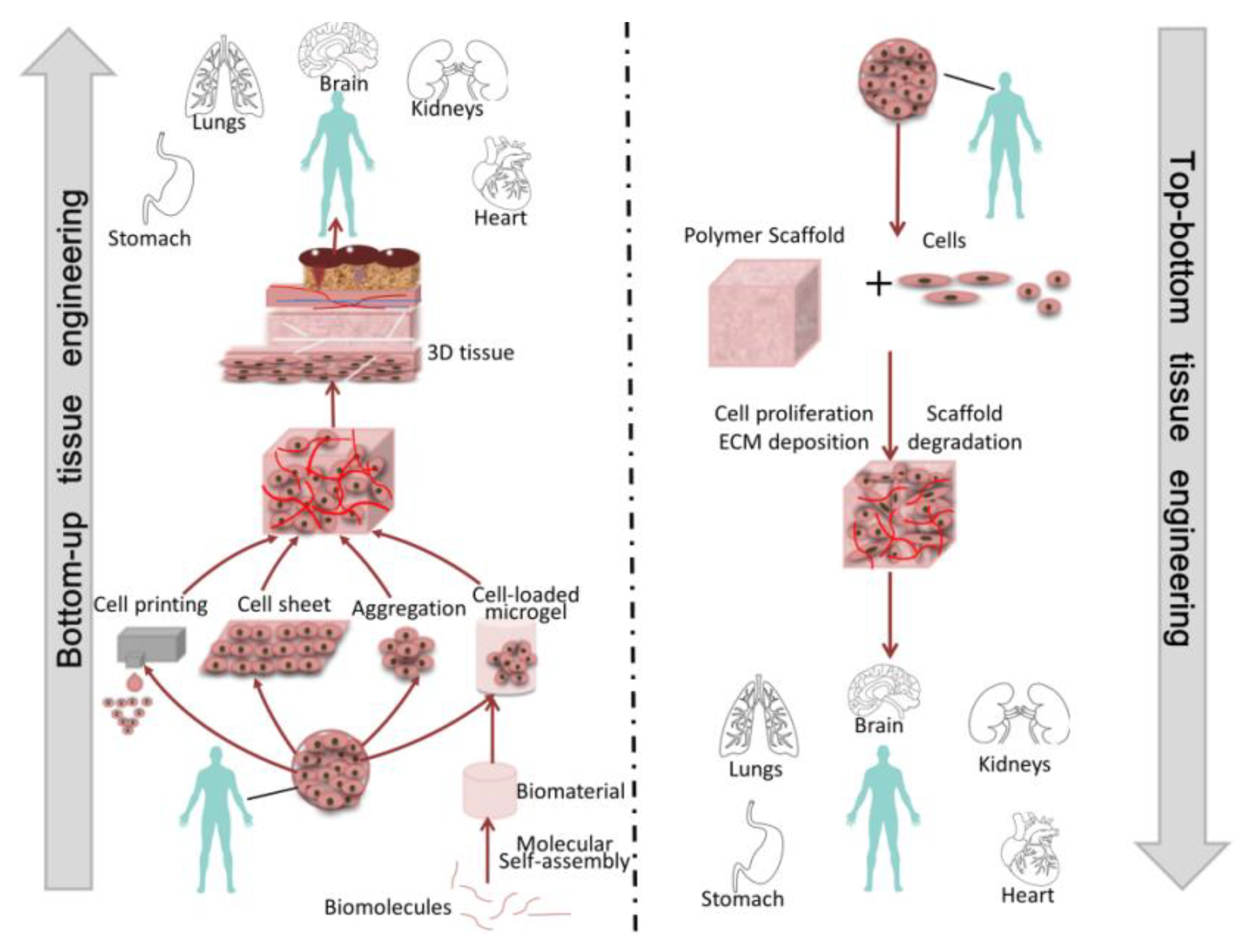
:1. Introduction
2. Module Manufacturing
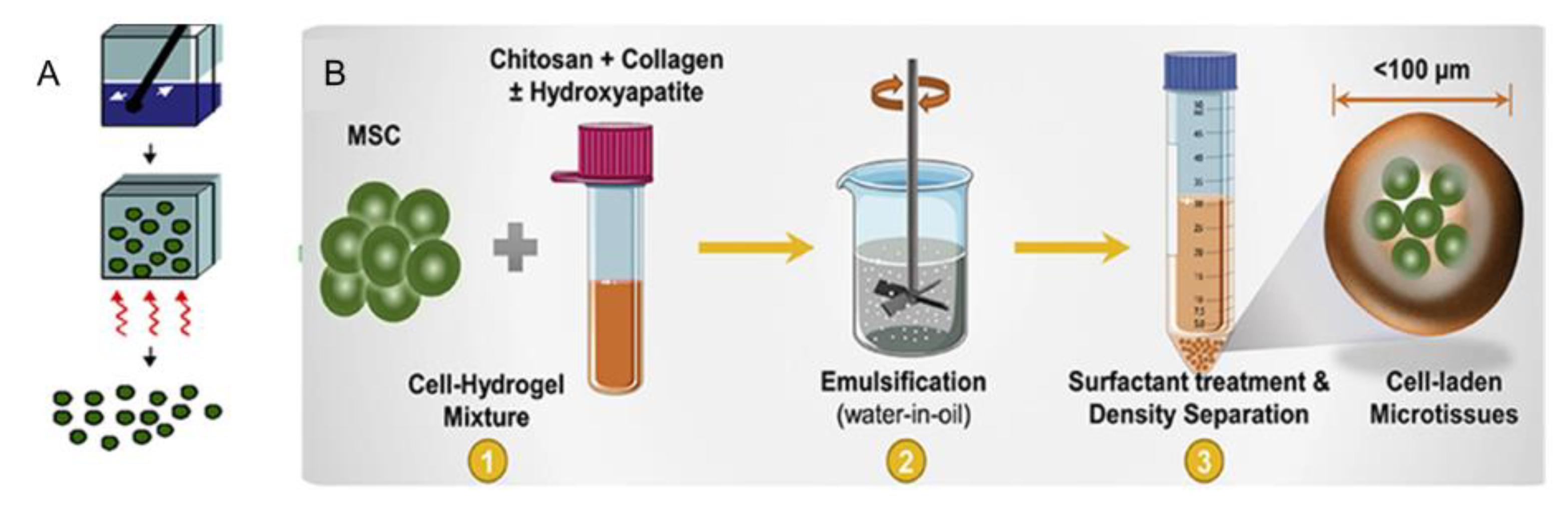
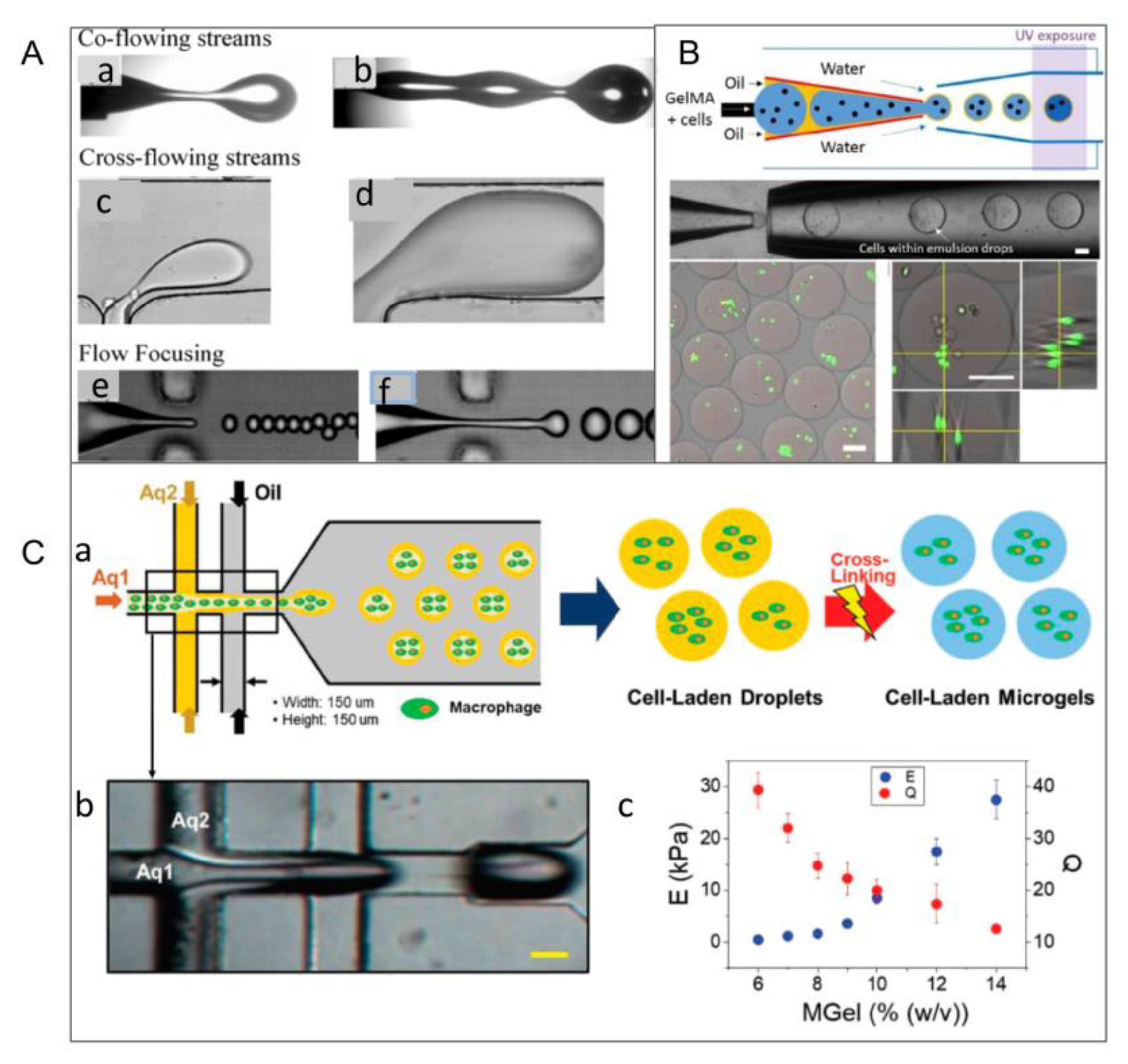
2.1. Emulsification Method
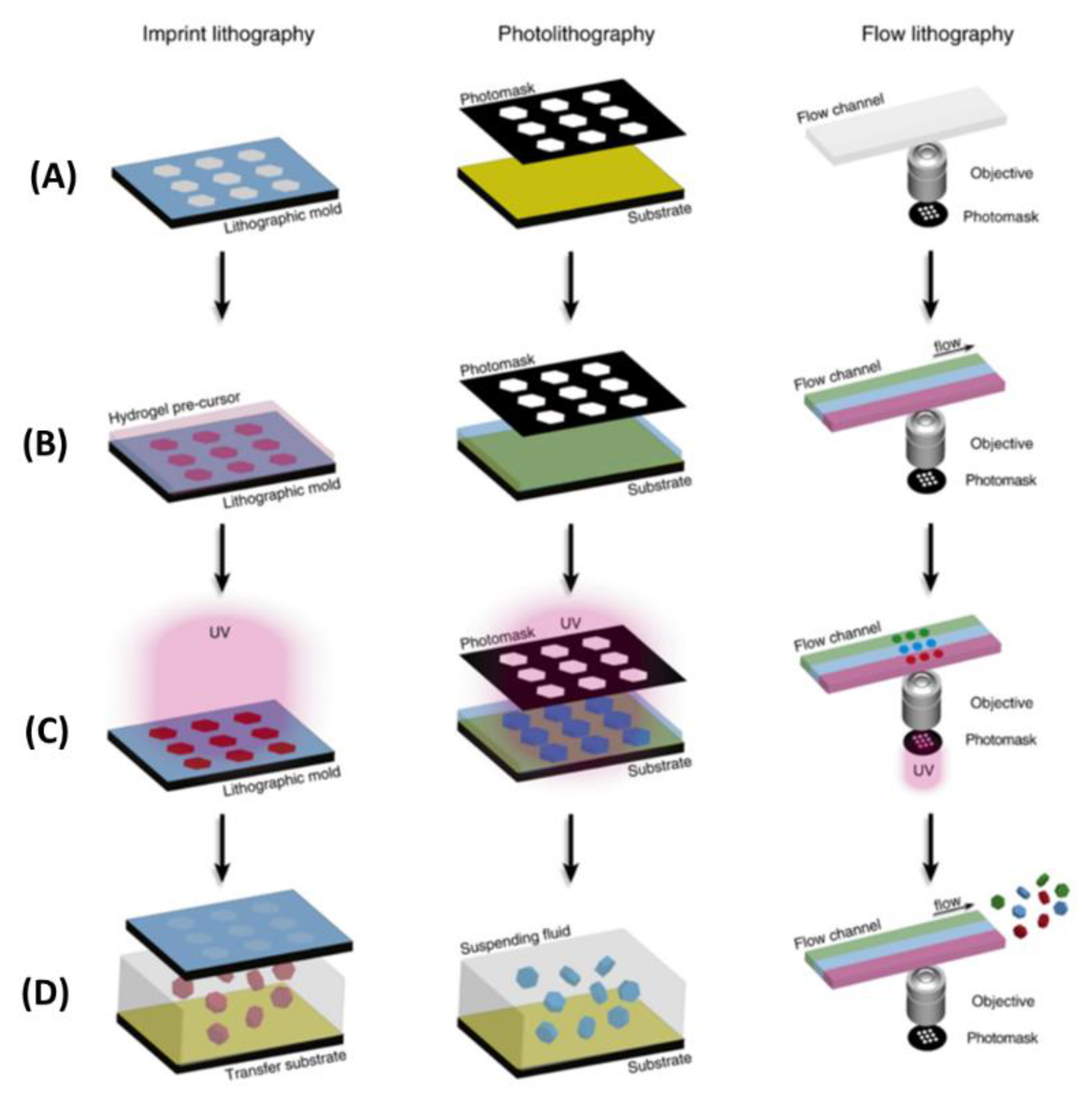
2.2. Optical-Based Fabricating Method
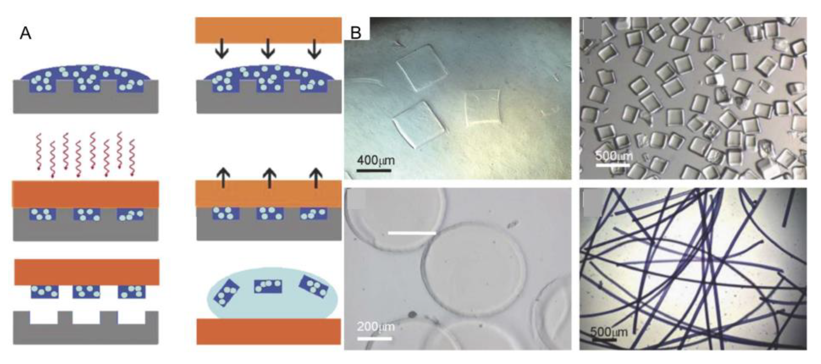
2.3. Micromolding Method
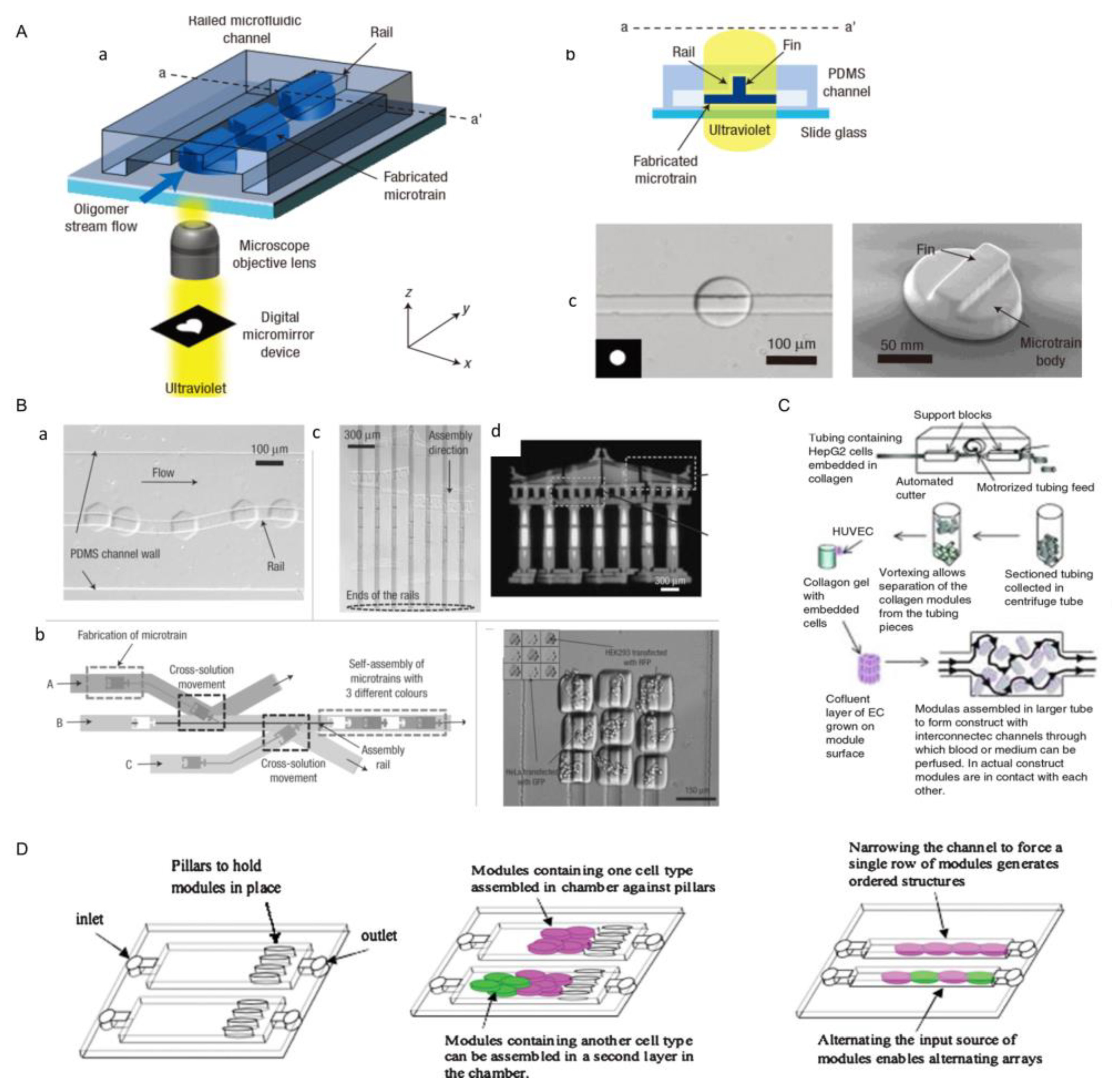
2.4. Microchannel Method
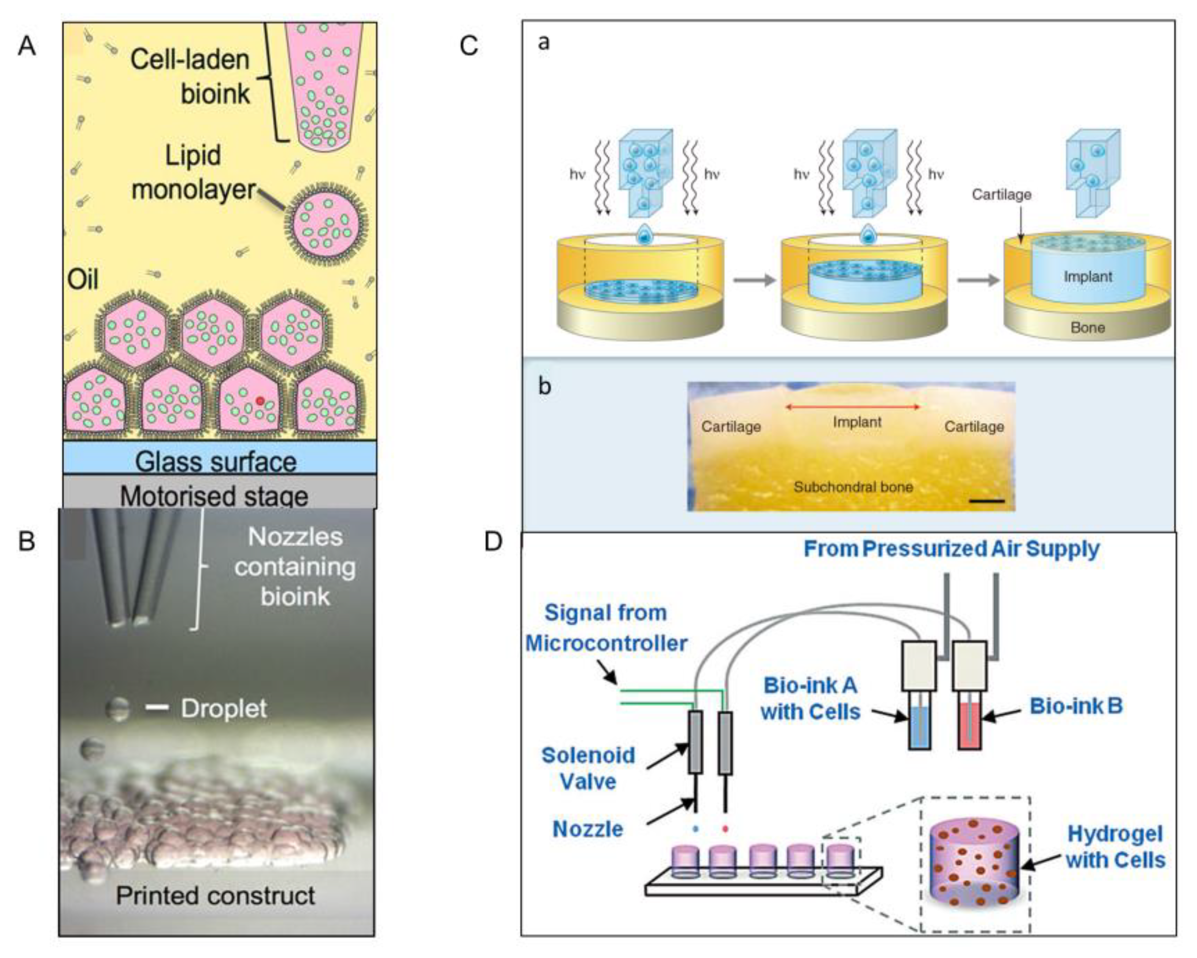
2.5. Bioprinting Technology
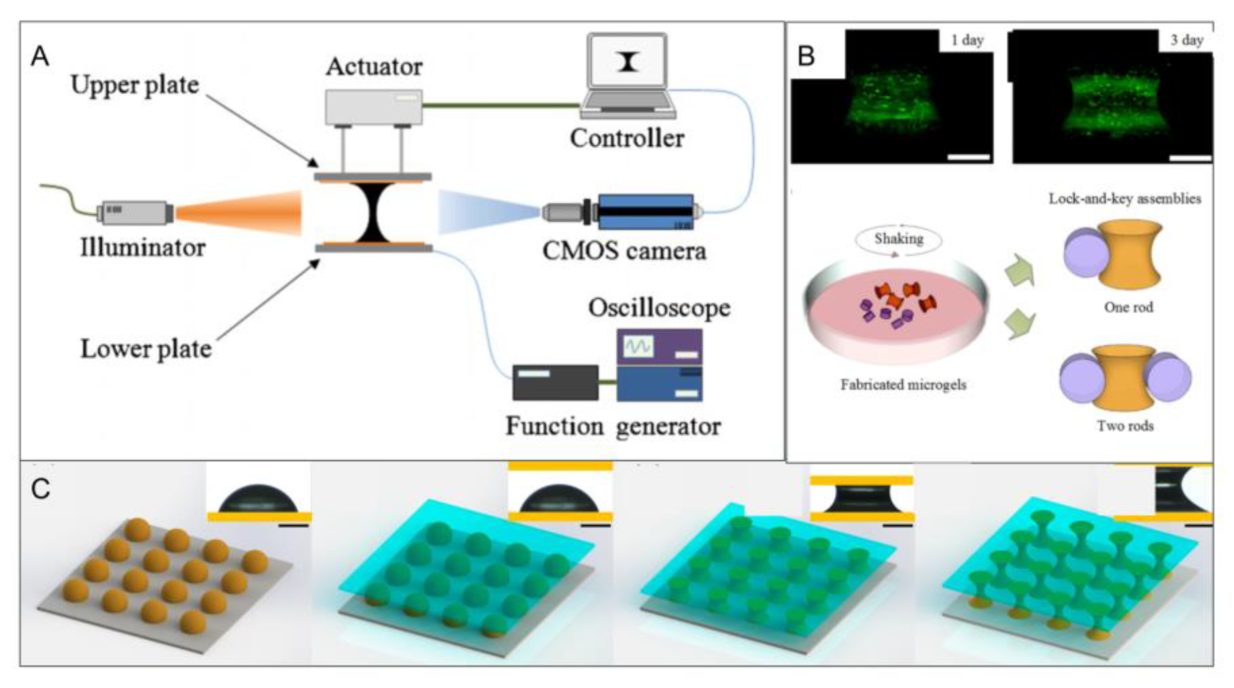
2.6. Liquid Bridge Method
3. Module Assembly
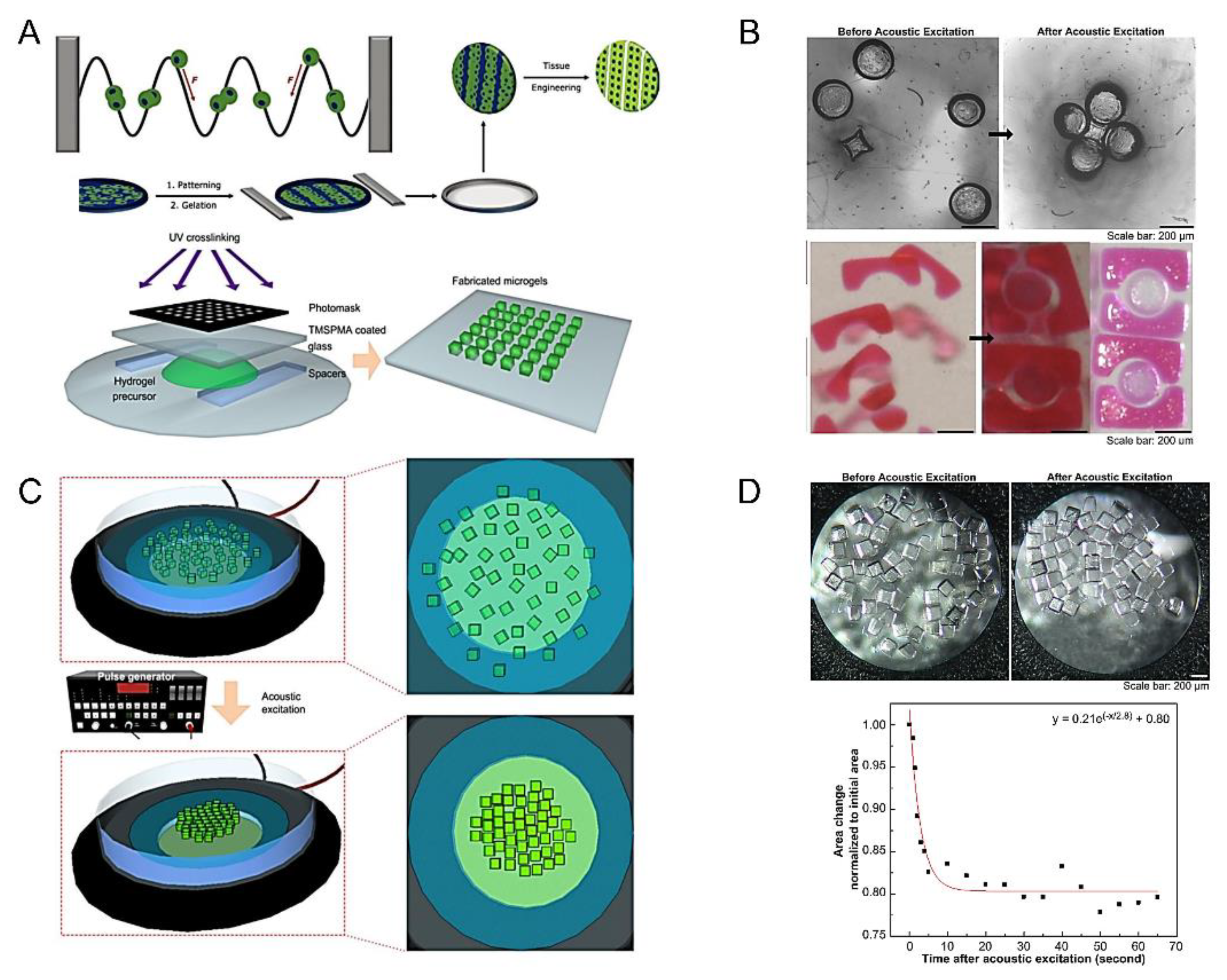
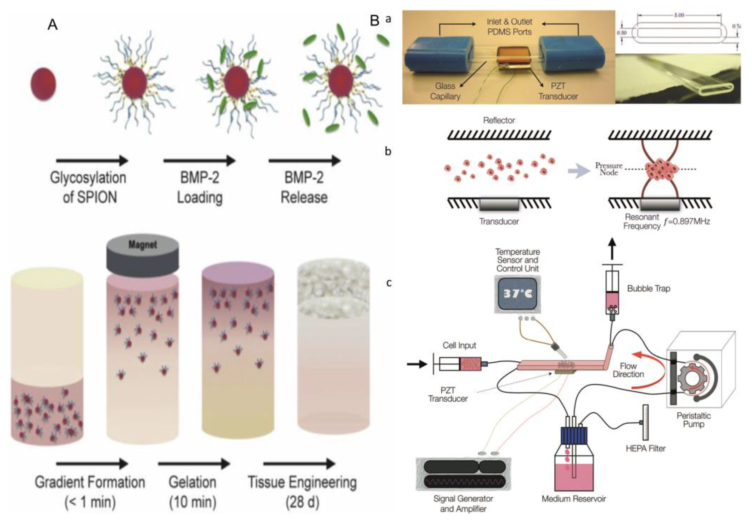
3.1. Acoustic Assembly
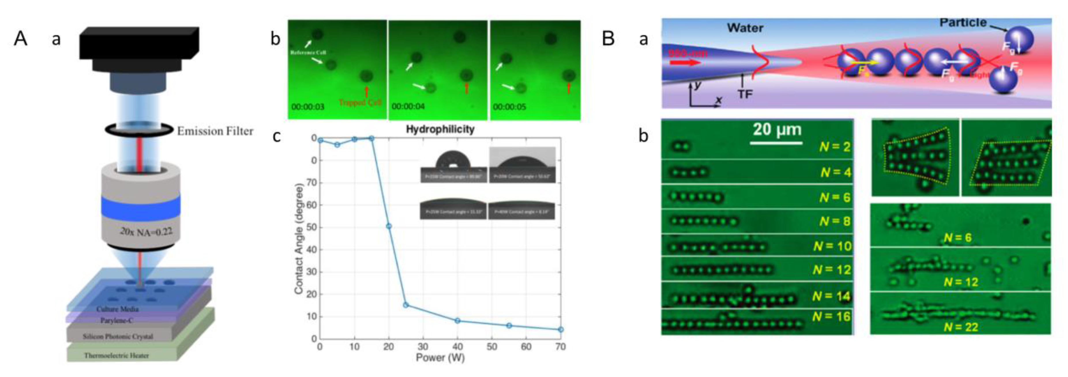
3.2. Optical Tweezers
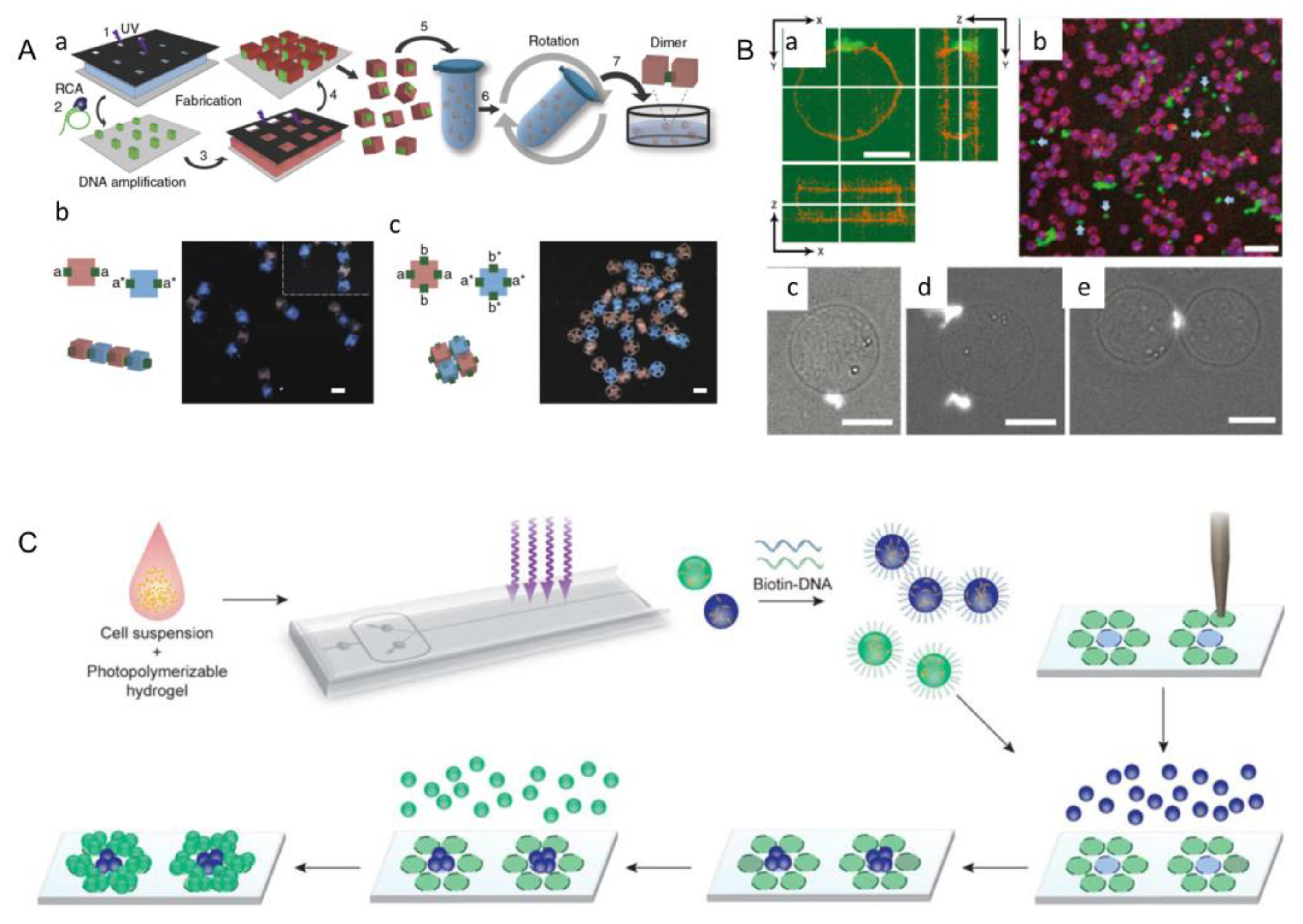
3.3. DNA-Assisted Assembly
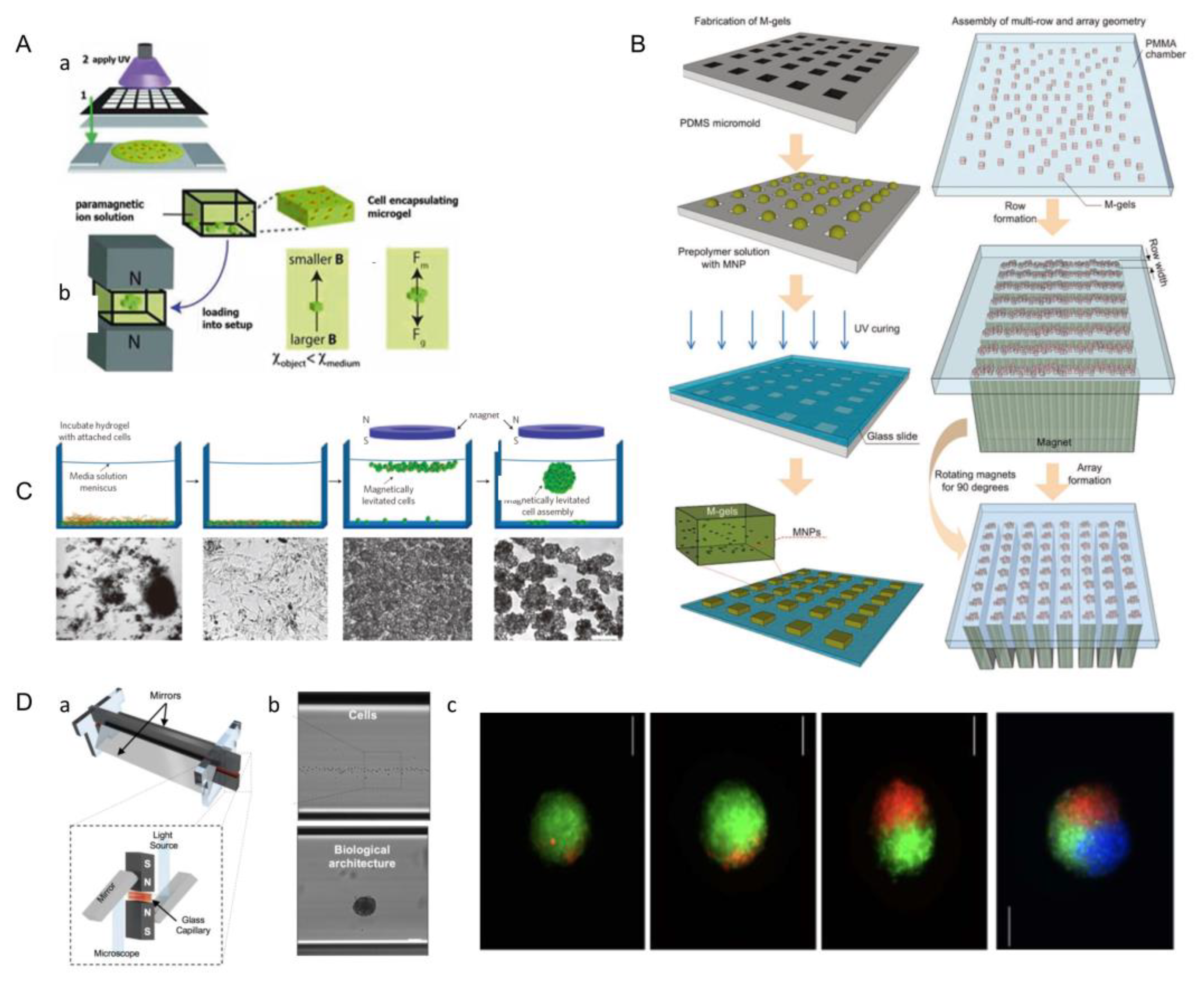
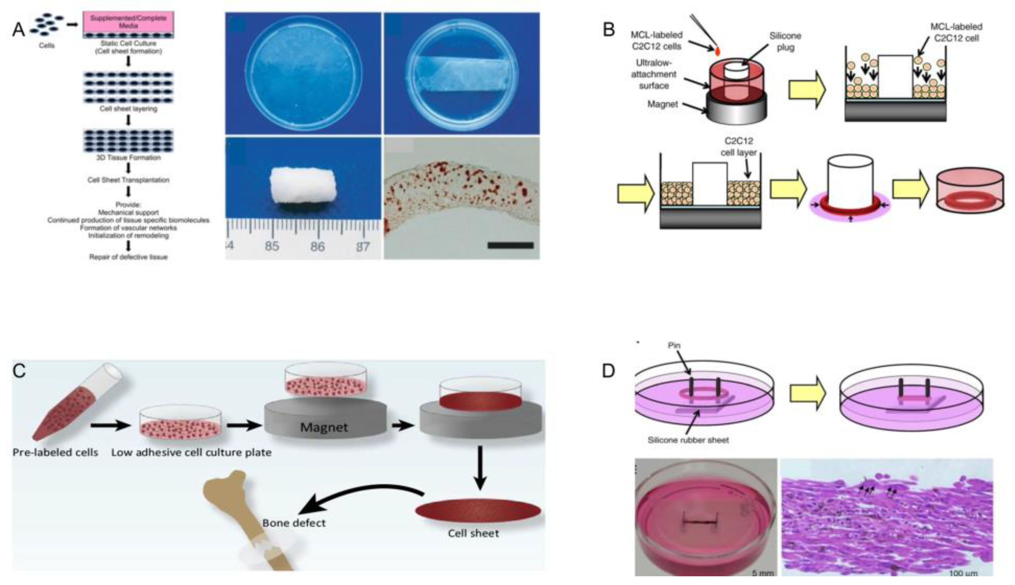
3.4. Magnetic-Assisted Assembly
3.5. Surface Modification
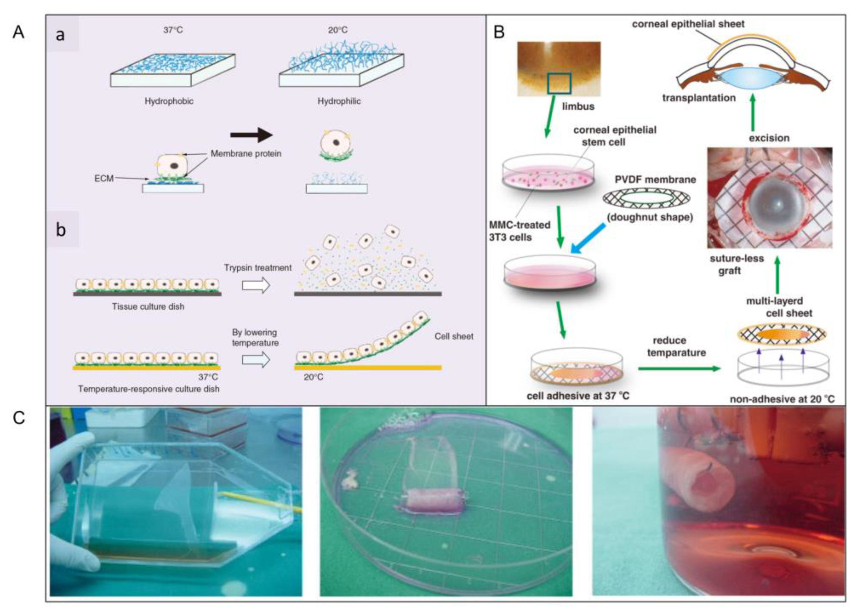
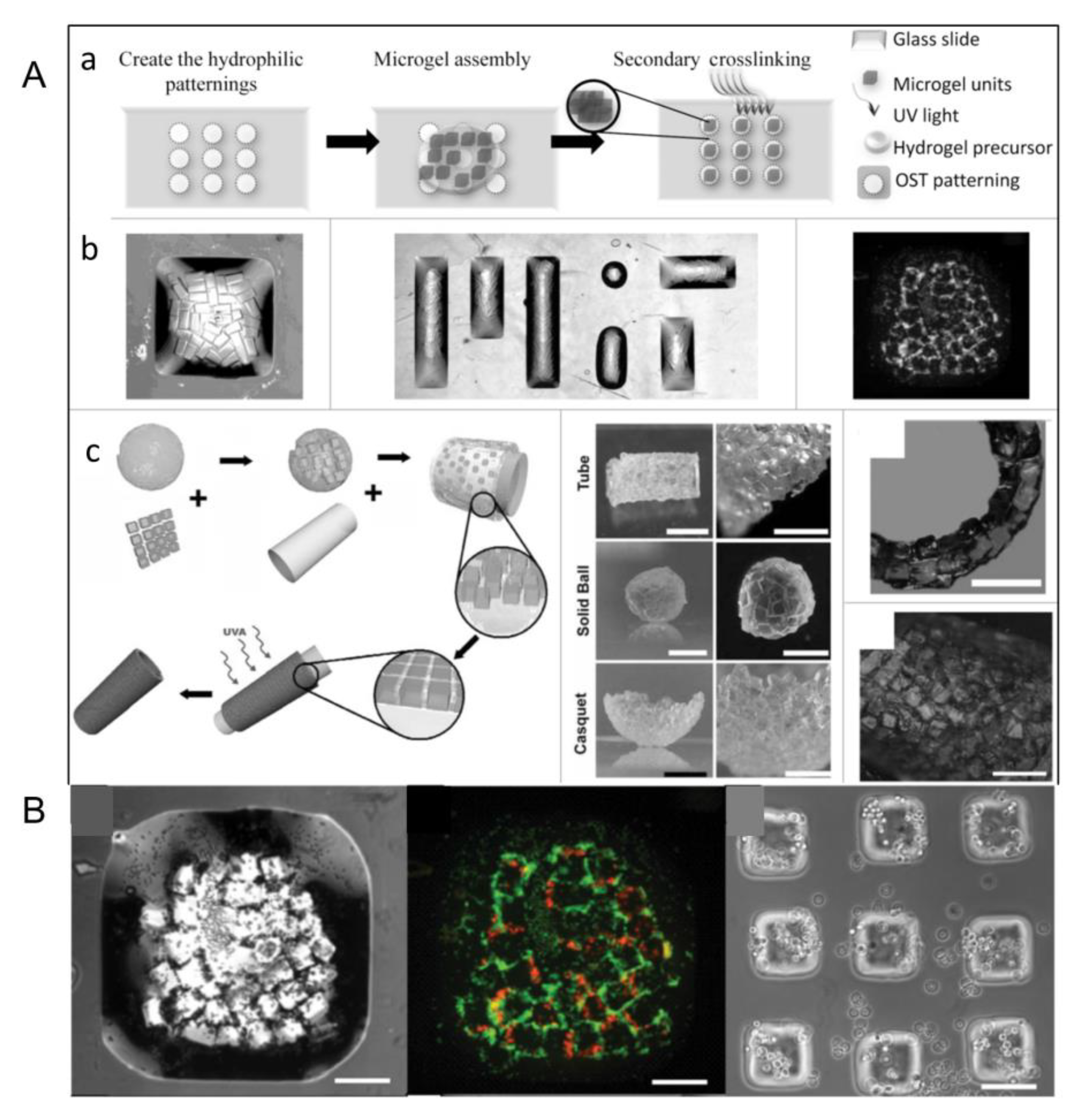
3.5.1. Thermosensitive Surface Hydrophobicity
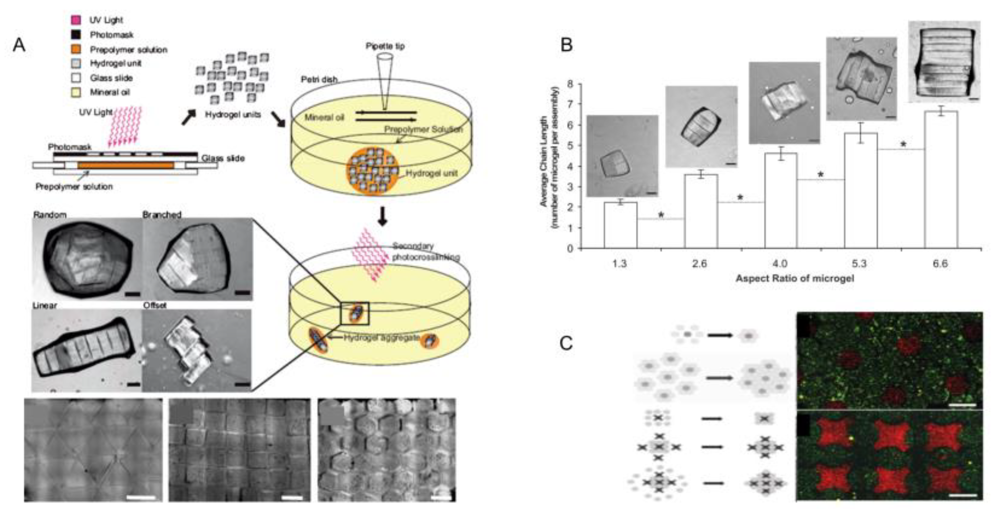
3.5.2. Directional Assembly on Hydrophilic and Hydrophobic Surfaces
3.5.3. Interface Self-Assembly
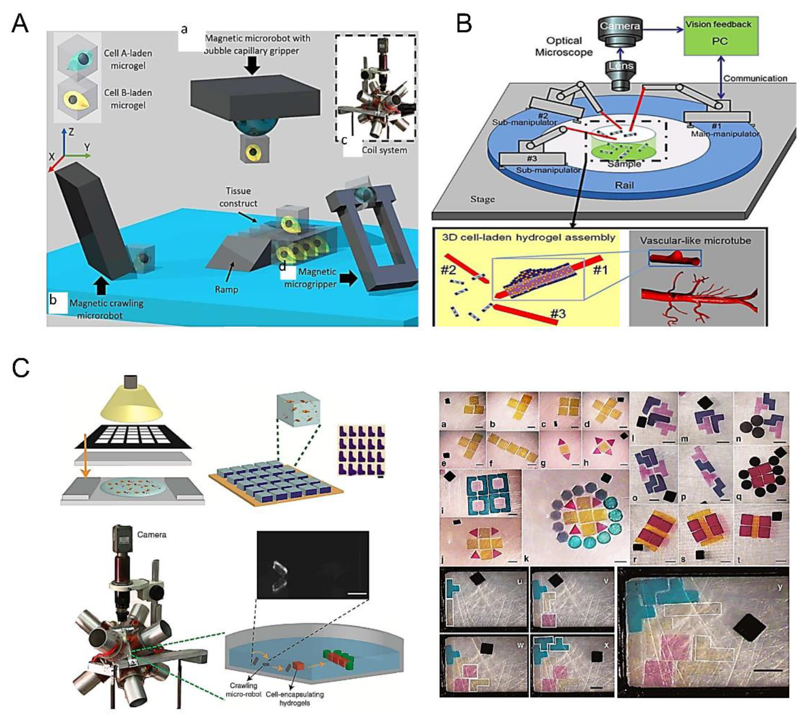
3.6. Robots-Assistant Assembly
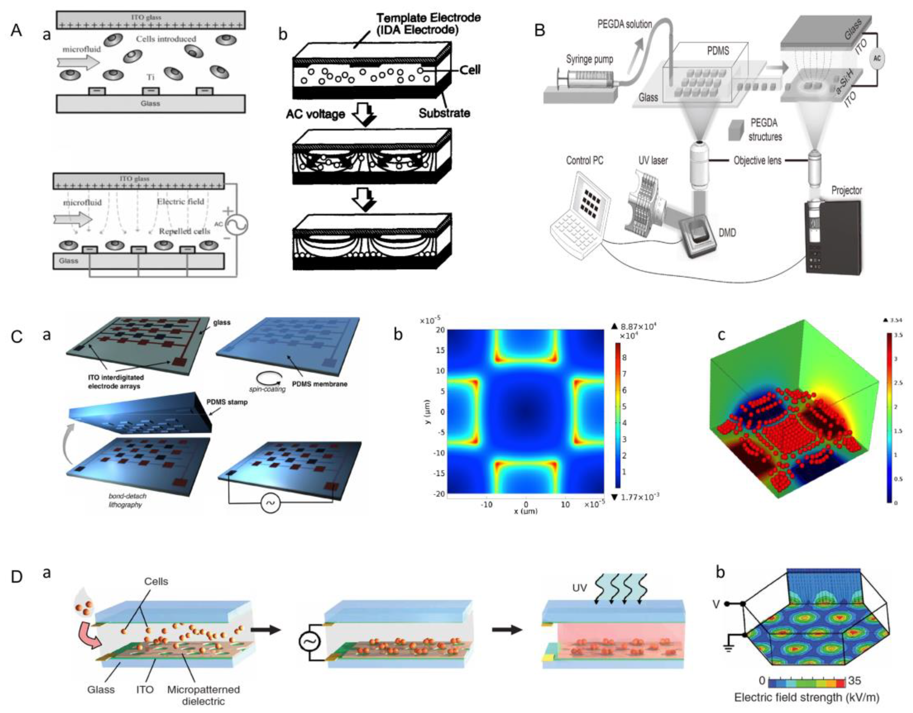
3.7. Dielectrophoresis Method
3.8. Microfluidic-Based Assembly
4. Application
4.1. Tissue Engineering
4.1.1. Bone Tissue
4.1.2. Cartilage Tissue
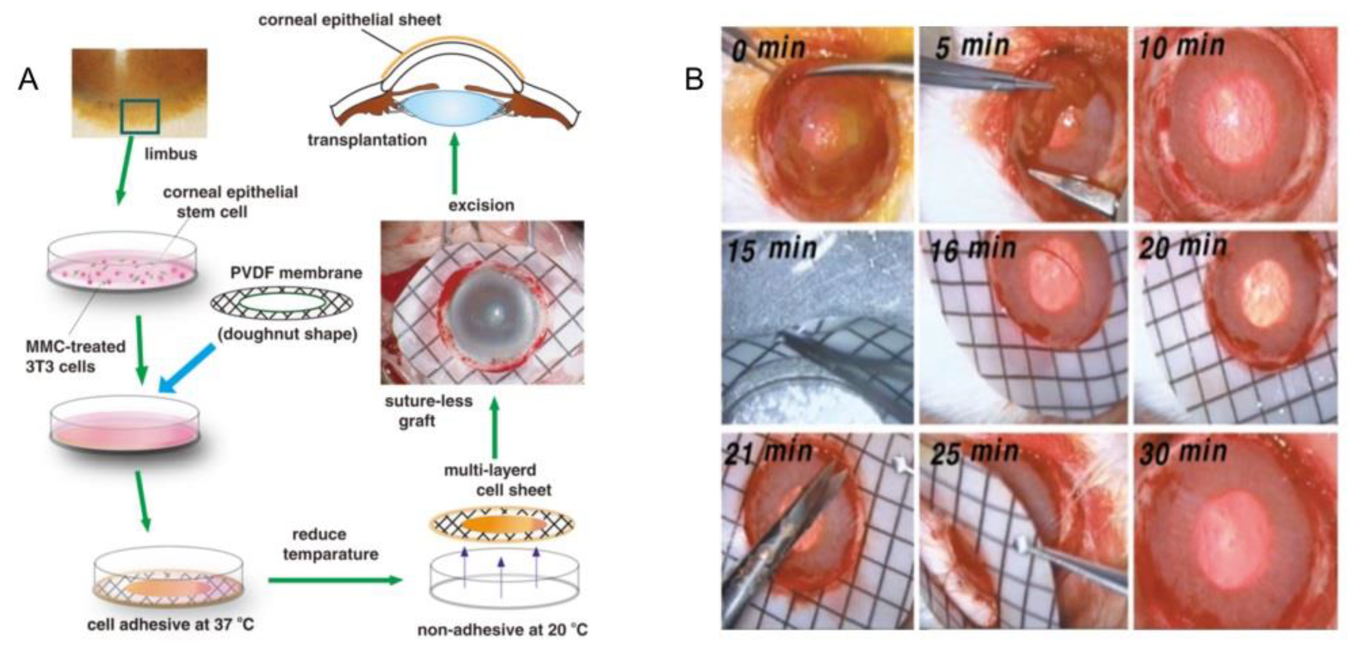
4.1.3. Corneal Epithelial Tissue
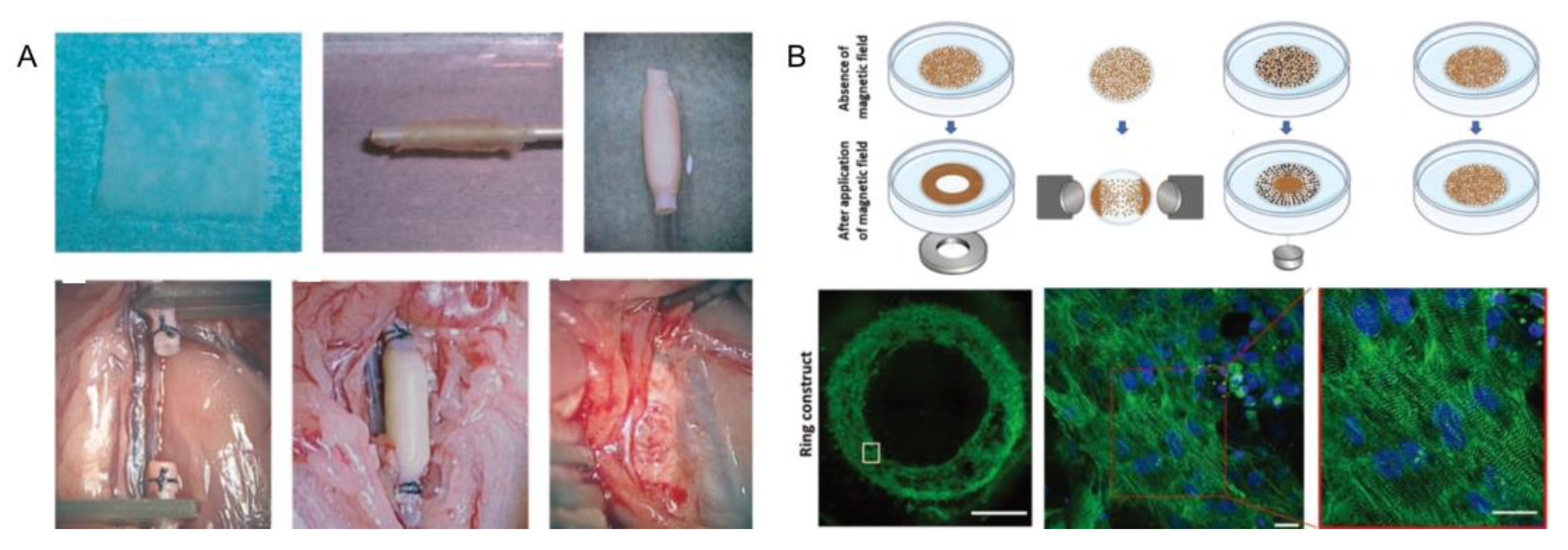
4.1.4. Myocardial Tube
4.1.5. Epicardium
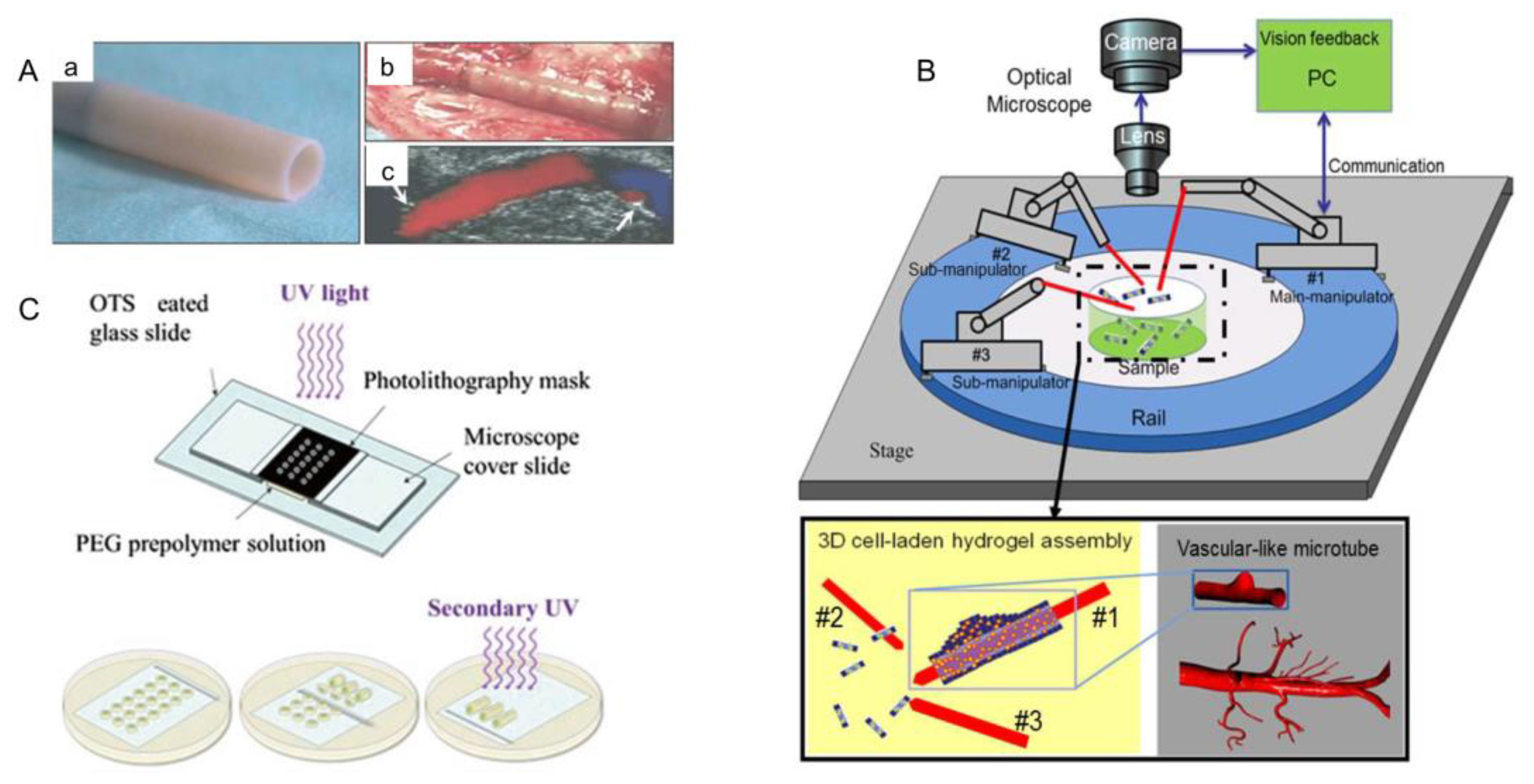
4.1.6. Blood Vessel
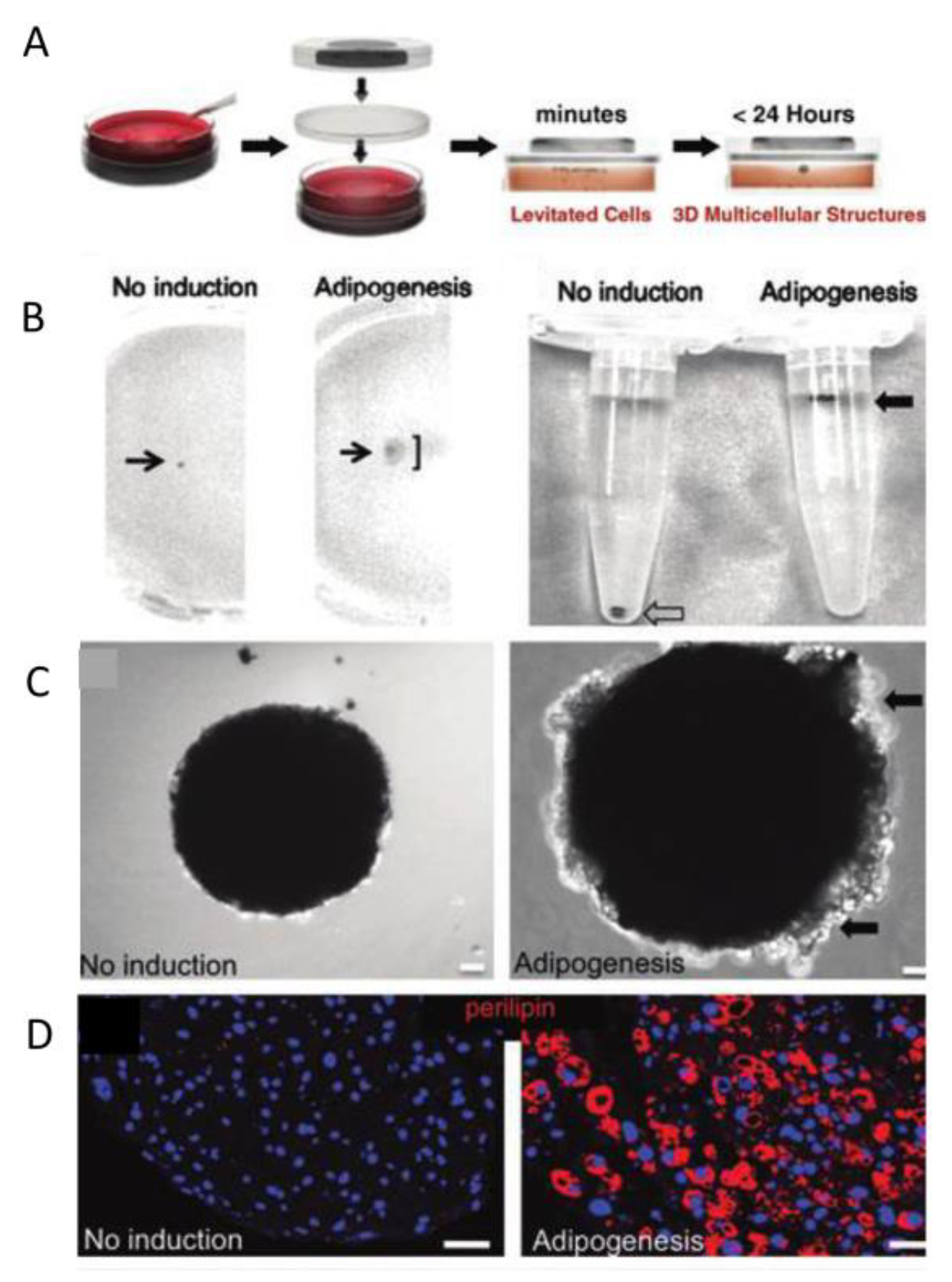
4.1.7. Adipose Tissue
4.2. Drug Screening
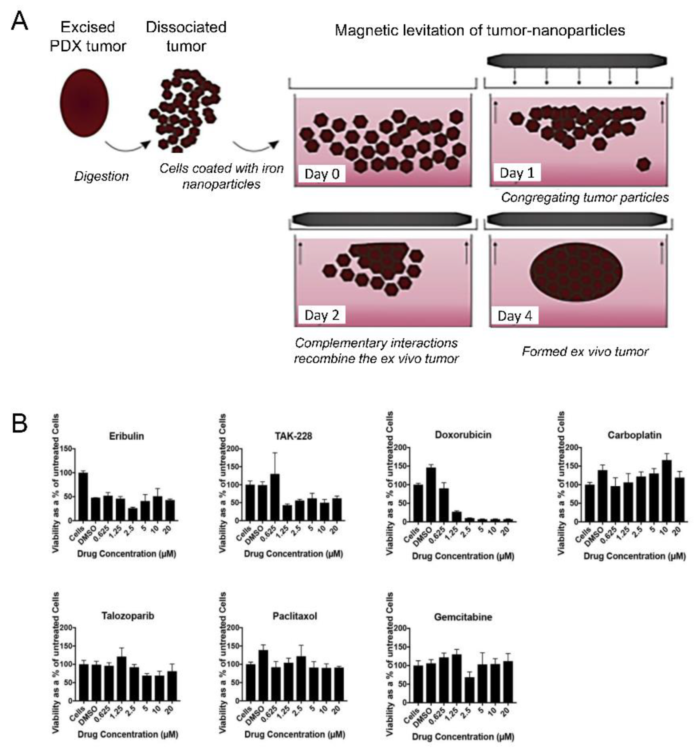
4.3. Cancer Treatment
5. Conclusions
Author Contributions
Funding
Data Availability Statement
Acknowledgments
Conflicts of Interest
References
- Nichol, J.W.; Khademhosseini, A. Modular tissue engineering: Engineering biological tissues from the bottom up. Soft Matter 2009, 5, 1312–1319. [Google Scholar] [CrossRef] [Green Version]
- Caddeo, S.; Boffito, M.; Sartori, S. Tissue Engineering Approaches in the Design of Healthy and Pathological In Vitro Tissue Models. Front. Bioeng. Biotechnol. 2017, 5, 40. [Google Scholar] [CrossRef] [Green Version]
- Bhatia, S.N.; Balis, U.J.; Yarmush, M.L.; Toner, M. Effect of cell–cell interactions in preservation of cellular phenotype: Cocultivation of hepatocytes and nonparenchymal cells. FASEB J. 1999, 13, 1883–1900. [Google Scholar] [CrossRef] [PubMed] [Green Version]
- Griffith, L.G.; Naughton, G. Tissue Engineering—Current Challenges and Expanding Opportunities. Science 2002, 295, 1009–1014. [Google Scholar] [CrossRef]
- Ikada, Y. Challenges in tissue engineering. J. R. Soc. Interface 2006, 3, 589–601. [Google Scholar] [CrossRef] [PubMed]
- Salerno, A.; Cesarelli, G.; Pedram, P.; Netti, P.A. Modular Strategies to Build Cell-Free and Cell-Laden Scaffolds towards Bioengineered Tissues and Organs. J. Clin. Med. 2019, 8, 1816. [Google Scholar] [CrossRef] [Green Version]
- Lanza, R.; Langer, R.; Vacanti, J. Principles of Tissue Engineering; Academic Press: London, UK, 2020. [Google Scholar]
- Feng, Q.; Li, D.; Li, Q.; Cao, X.; Dong, H. Microgel assembly: Fabrication, characteristics and application in tissue engineering and regenerative medicine. Bioact. Mater. 2021, 9, 105–119. [Google Scholar] [CrossRef] [PubMed]
- Yang, W.; Cai, S.; Chen, Y.; Liang, W.; Lai, Y.; Yu, H.; Wang, Y.; Liu, L. 3D Functional Microgels: Modular and Customized Fabrication of 3D Functional Microgels for Bottom-Up Tissue Engineering and Drug Screening. Adv. Mater. Technol. 2020, 5, 2070024. [Google Scholar] [CrossRef]
- Chen, G.; Qi, Y.; Niu, L.; Di, T.; Zhong, J.; Fang, T.; Yan, W. Application of the cell sheet technique in tissue engineering. Biomed. Rep. 2015, 3, 749–757. [Google Scholar] [CrossRef] [Green Version]
- Chu, H.; Yang, W.; Sun, L.; Cai, S.; Yang, R.; Liang, W.; Yu, H.; Liu, L. 4D Printing: A Review on Recent Progresses. Micromachines 2020, 11, 796. [Google Scholar] [CrossRef]
- Lee, J.K.; Link, J.M.; Hu, J.C.Y.; Athanasiou, K.A. The Self-Assembling Process and Applications in Tissue Engineering. Cold Spring Harb. Perspect. Med. 2017, 7, a025668. [Google Scholar] [CrossRef]
- Rijal, G.; Li, W. Native-mimicking in vitro microenvironment: An elusive and seductive future for tumor modeling and tissue engineering. J. Biol. Eng. 2018, 12, 20. [Google Scholar] [CrossRef] [Green Version]
- Hedegaard, C.L.; Mata, A. Integrating self-assembly and biofabrication for the development of structures with enhanced complexity and hierarchical control. Biofabrication 2020, 12, 032002. [Google Scholar] [CrossRef] [PubMed]
- Allen, J.W.; Hassanein, T.; Bhatia, S.N. Advances in bioartificial liver devices. Hepatology 2001, 34, 447–455. [Google Scholar] [CrossRef] [PubMed] [Green Version]
- Elbert, D.L. Bottom-up tissue engineering. Curr. Opin. Biotechnol. 2011, 22, 674–680. [Google Scholar] [CrossRef] [Green Version]
- De Pieri, A.; Rochev, Y.; Zeugolis, D.I. Scaffold-free cell-based tissue engineering therapies: Advances, shortfalls and forecast. NPJ Regen. Med. 2021, 6, 18. [Google Scholar] [CrossRef]
- Schmidt, T.; Xiang, Y.; Bao, X.; Sun, T. A Paradigm Shift in Tissue Engineering: From a Top–Down to a Bottom–Up Strategy. Processes 2021, 9, 935. [Google Scholar] [CrossRef]
- Liu, J.S.; Gartner, Z.J. Directing the assembly of spatially organized multicomponent tissues from the bottom up. Trends Cell Biol. 2012, 22, 683–691. [Google Scholar] [CrossRef] [Green Version]
- Khademhosseini, A.; Langer, R. Microengineered hydrogels for tissue engineering. Biomaterials 2007, 28, 5087–5092. [Google Scholar] [CrossRef]
- Ahmed, E.M. Hydrogel: Preparation, characterization, and applications: A review. J. Adv. Res. 2015, 6, 105–121. [Google Scholar] [CrossRef] [Green Version]
- Kopeček, J. Hydrogel biomaterials: A smart future? Biomaterials 2007, 28, 5185–5192. [Google Scholar] [CrossRef] [Green Version]
- Alzanbaki, H.; Moretti, M.; Hauser, C.A.E. Engineered Microgels—Their Manufacturing and Biomedical Applications. Micromachines 2021, 12, 45. [Google Scholar] [CrossRef]
- McGuigan, A.P.; Leung, B.; Sefton, M.V. Fabrication of cells containing gel modules to assemble modular tissue-engineered constructs. Nat. Protoc. 2006, 1, 2963–2969. [Google Scholar] [CrossRef] [PubMed]
- Kachouie, N.N.; Du, Y.; Bae, H.; Khabiry, M.; Ahari, A.F.; Zamanian, B.; Fukuda, J.; Khademhosseini, A. Directed assembly of cell-laden hydrogels for engineering functional tissues. Organogenesis 2010, 6, 234–244. [Google Scholar] [CrossRef] [PubMed] [Green Version]
- Howard, J.M. Optical design using computer graphics. Appl. Opt. 2001, 40, 3225–3231. [Google Scholar] [CrossRef]
- Helgeson, M.E.; Chapin, S.C.; Doyle, P.S. Hydrogel microparticles from lithographic processes: Novel materials for fundamental and applied colloid science. Curr. Opin. Colloid Interface Sci. 2011, 16, 106–117. [Google Scholar] [CrossRef] [PubMed] [Green Version]
- Chung, B.G.; Lee, K.-H.; Khademhosseini, A.; Lee, S.-H. Microfluidic fabrication of microengineered hydrogels and their application in tissue engineering. Lab Chip 2012, 12, 45–59. [Google Scholar] [CrossRef] [PubMed]
- Utada, A.S.; Lorenceau, E.; Link, D.R.; Kaplan, P.D.; Stone, H.A.; Weitz, D.A. Monodisperse Double Emulsions Generated from a Microcapillary Device. Science 2005, 308, 537–541. [Google Scholar] [CrossRef] [PubMed] [Green Version]
- Christopher, G.; Anna, S. Topical Review: Microfluidic methods for generating continuous droplet streams. J. Phys. D Appl. Phys. 2007, 40, R319. [Google Scholar] [CrossRef]
- Du, Y.; Ghodousi, M.; Qi, H.; Haas, N.; Xiao, W.; Khademhosseini, A. Sequential assembly of cell-laden hydrogel constructs to engineer vascular-like microchannels. Biotechnol. Bioeng. 2011, 108, 1693–1703. [Google Scholar] [CrossRef] [PubMed] [Green Version]
- Ma, S.; Thiele, J.; Liu, X.; Bai, Y.; Abell, C.; Huck, W.T.S. Fabrication of Microgel Particles with Complex Shape via Selective Polymerization of Aqueous Two-Phase Systems. Small 2012, 8, 2356–2360. [Google Scholar] [CrossRef] [PubMed]
- Choi, C.-H.; Wang, H.; Lee, H.; Kim, J.H.; Zhang, L.; Mao, A.; Mooney, D.; Weitz, D.A. One-step generation of cell-laden microgels using double emulsion drops with a sacrificial ultra-thin oil shell. Lab Chip 2016, 16, 1549–1555. [Google Scholar] [CrossRef] [PubMed] [Green Version]
- Huang, L.; Abdalla, A.M.; Xiao, L.; Yang, G. Biopolymer-Based Microcarriers for Three-Dimensional Cell Culture and Engineered Tissue Formation. Int. J. Mol. Sci. 2020, 21, 1895. [Google Scholar] [CrossRef] [PubMed] [Green Version]
- Shao, F.; Yu, L.; Zhang, Y.; An, C.; Zhang, H.; Zhang, Y.; Xiong, Y.; Wang, H. Microfluidic Encapsulation of Single Cells by Alginate Microgels Using a Trigger-Gellified Strategy. Front. Bioeng. Biotechnol. 2020, 8, 583065. [Google Scholar] [CrossRef] [PubMed]
- Kang, H.W.; Sung, H.J.; Lee, T.-M.; Kim, D.-S.; Kim, C.-J. “cj” Liquid transfer between two separating plates for micro-gravure-offset printing. J. Micromech. Microeng. 2008, 19, 015025. [Google Scholar] [CrossRef] [Green Version]
- Chen, H.; Amirfazli, A.; Tang, T. Modeling Liquid Bridge between Surfaces with Contact Angle Hysteresis. Langmuir 2013, 29, 3310–3319. [Google Scholar] [CrossRef] [PubMed]
- Wang, L.; Qiu, M.; Yang, Q.; Li, Y.; Huang, G.; Lin, M.; Lu, T.J.; Xu, F. Fabrication of Microscale Hydrogels with Tailored Microstructures based on Liquid Bridge Phenomenon. ACS Appl. Mater. Interfaces 2015, 7, 11134–11140. [Google Scholar] [CrossRef]
- Yeh, J.; Ling, Y.; Karp, J.M.; Gantz, J.; Chandawarkar, A.; Eng, G.; Iii, J.B.; Langer, R.; Khademhosseini, A. Micromolding of shape-controlled, harvestable cell-laden hydrogels. Biomaterials 2006, 27, 5391–5398. [Google Scholar] [CrossRef]
- Charnley, M.; Textor, M.; Khademhosseini, A.; Lutolf, M.P. Integration column: Microwell arrays for mammalian cell culture. Integr. Biol. 2009, 1, 625–634. [Google Scholar] [CrossRef]
- Derby, B. Printing and Prototyping of Tissues and Scaffolds. Sciience 2012, 338, 921–926. [Google Scholar] [CrossRef] [Green Version]
- Li, C.; Faulkner-Jones, A.; Dun, A.R.; Jin, J.; Chen, P.; Xing, Y.; Yang, Z.; Li, Z.; Shu, W.; Liu, D.; et al. Rapid Formation of a Supramolecular Polypeptide-DNA Hydrogel for In Situ Three-Dimensional Multilayer Bioprinting. Angew. Chem. Int. Ed. 2015, 54, 3957–3961. [Google Scholar] [CrossRef] [PubMed]
- Graham, A.D.; Olof, S.N.; Burke, M.J.; Armstrong, J.P.; Mikhailova, E.A.; Nicholson, J.; Box, S.; Szele, F.G.; Perriman, A.; Bayley, H. High-Resolution Patterned Cellular Constructs by Droplet-Based 3D Printing. Sci. Rep. 2017, 7, 7004. [Google Scholar] [CrossRef]
- Liu, T.-K.; Pang, Y.; Zhou, Z.-Z.; Yao, R.; Sun, W. An integrated cell printing system for the construction of heterogeneous tissue models. Acta Biomater. 2019, 95, 245–257. [Google Scholar] [CrossRef] [PubMed]
- Yang, W.; Yu, H.; Li, G.; Wang, Y.; Liu, L. High-Throughput Fabrication and Modular Assembly of 3D Heterogeneous Microscale Tissues. Small 2017, 13, 1602769. [Google Scholar] [CrossRef] [PubMed]
- Armada-Moreira, A.; Taipaleenmäki, E.; Itel, F.; Zhang, Y.; Städler, B. Droplet-microfluidics towards the assembly of advanced building blocks in cell mimicry. Nanoscale 2016, 8, 19510–19522. [Google Scholar] [CrossRef] [PubMed]
- Yamada, M.; Seki, M. High-Throughput Cell Assembly Featuring Heterogeneous Hydrogels Produced by Using Microfluidic Devices, in Hyper Bio Assembler for 3D Cellular Systems; Arai, T., Arai, F., Yamato, M., Eds.; Springer: Tokyo, Japan, 2015; pp. 129–150. [Google Scholar]
- Du, Y.; Lo, E.; Vidula, M.K.; Khabiry, M.; Khademhosseini, A. Method of Bottom-Up Directed Assembly of Cell-Laden Microgels. Cell. Mol. Bioeng. 2008, 1, 157–162. [Google Scholar] [CrossRef] [PubMed] [Green Version]
- Fernandez, J.G.; Khademhosseini, A. Micro-Masonry: Construction of 3D Structures by Microscale Self-Assembly. Adv. Mater. 2010, 22, 2538–2541. [Google Scholar] [CrossRef] [Green Version]
- Guo, Y.; Bae, J.; Fang, Z.; Li, P.; Zhao, F.; Yu, G. Hydrogels and Hydrogel-Derived Materials for Energy and Water Sustainability. Chem. Rev. 2020, 120, 7642–7707. [Google Scholar] [CrossRef]
- Farjami, T.; Madadlou, A. Fabrication methods of biopolymeric microgels and microgel-based hydrogels. Food Hydrocoll. 2017, 62, 262–272. [Google Scholar] [CrossRef]
- Yamada, N.; Okano, T.; Sakai, H.; Karikusa, F.; Sawasaki, Y.; Sakurai, Y. Thermo-responsive polymeric surfaces; control of attachment and detachment of cultured cells. Die Makromol. Chem. Rapid Commun. 1990, 11, 571–576. [Google Scholar] [CrossRef]
- Okano, T.; Yamada, N.; Okuhara, M.; Sakai, H.; Sakurai, Y. Mechanism of cell detachment from temperature-modulated, hydrophilic-hydrophobic polymer surfaces. Biomaterials 1995, 16, 297–303. [Google Scholar] [CrossRef]
- Ito, Y.; Chen, G.; Guan, A.Y.; Imanishi, Y. Patterned Immobilization of Thermoresponsive Polymer. Langmuir 1997, 13, 2756–2759. [Google Scholar] [CrossRef]
- Shiroyanagi, Y.; Yamato, M.; Yamazaki, Y.; Toma, H.; Okano, T. Transplantable Urothelial Cell Sheets Harvested Noninvasively from Temperature-Responsive Culture Surfaces by Reducing Temperature. Tissue Eng. 2003, 9, 1005–1012. [Google Scholar] [CrossRef] [PubMed]
- Nishida, K.; Yamato, M.; Hayashida, Y.; Watanabe, K.; Maeda, N.; Watanabe, H.; Yamamoto, K.; Nagai, S.; Kikuchi, A.; Tano, Y.; et al. Functional bioengineered corneal epithelial sheet grafts from corneal stem cells expanded ex vivo on a temperature-responsive cell culture surface. Transplantation 2004, 77, 379–385. [Google Scholar] [CrossRef] [PubMed]
- Wang, S.; Liu, H.; Liu, D.; Ma, X.; Fang, X.; Jiang, L. Enthalpy-Driven Three-State Switching of a Superhydrophilic/Superhydrophobic Surface. Angew. Chem. Int. Ed. 2007, 46, 3915–3917. [Google Scholar] [CrossRef]
- Du, Y.; Lo, E.; Ali, S.; Khademhosseini, A. Directed assembly of cell-laden microgels for fabrication of 3D tissue constructs. Proc. Natl. Acad. Sci. USA 2008, 105, 9522–9527. [Google Scholar] [CrossRef] [Green Version]
- Du, Y.; Ghodousi, M.; Lo, E.; Vidula, M.K.; Emiroglu, O.; Khademhosseini, A. Surface-directed assembly of cell-laden microgels. Biotechnol. Bioeng. 2010, 105, 655–662. [Google Scholar] [CrossRef] [Green Version]
- Zamanian, B.; Masaeli, M.; Nichol, J.W.; Khabiry, M.; Hancock, M.; Bae, H.; Khademhosseini, A. Interface-Directed Self-Assembly of Cell-Laden Microgels. Small 2010, 6, 937–944. [Google Scholar] [CrossRef] [PubMed] [Green Version]
- Ward, M.A.; Georgiou, T.K. Thermoresponsive Polymers for Biomedical Applications. Polymers 2011, 3, 1215. [Google Scholar] [CrossRef] [Green Version]
- Yang, W.; Yu, H.; Liang, W.; Wang, Y.; Liu, L. Rapid Fabrication of Hydrogel Microstructures Using UV-Induced Projection Printing. Micromachines 2015, 6, 1903–1913. [Google Scholar] [CrossRef] [Green Version]
- Yang, W.; Yu, H.; Wei, F.; Li, G.; Wang, Y.; Liu, L. Selective pattern of cancer cell accumulation and growth using UV modulating printing of hydrogels. Biomed. Microdevices 2015, 17, 104. [Google Scholar] [CrossRef] [PubMed]
- Moschouris, K.; Firoozi, N.; Kang, Y. The application of cell sheet engineering in the vascularization of tissue regeneration. Regen. Med. 2016, 11, 559–570. [Google Scholar] [CrossRef] [Green Version]
- Arrebola, I.N.; Billon, L.; Aguirre, G. Microgels self-assembly at liquid/liquid interface as stabilizers of emulsion: Past, present & future. Adv. Colloid Interface Sci. 2020, 287, 102333. [Google Scholar] [CrossRef]
- Akiyama, H.; Ito, A.; Kawabe, Y.; Kamihira, M. Fabrication of complex three-dimensional tissue architectures using a magnetic force-based cell patterning technique. Biomed. Microdevices 2009, 11, 713–721. [Google Scholar] [CrossRef] [PubMed]
- Souza, G.R.; Molina, J.R.; Raphael, R.M.; Ozawa, M.G.; Stark, D.J.; Levin, C.S.; Bronk, L.; Ananta, J.S.; Mandelin, J.; Georgescu, M.-M.; et al. Three-dimensional tissue culture based on magnetic cell levitation. Nat. Nanotechnol. 2010, 5, 291–296. [Google Scholar] [CrossRef] [PubMed] [Green Version]
- Xu, F.; Wu, C.-A.M.; Rengarajan, V.; Finley, T.D.; Keles, H.O.; Sung, Y.; Li, B.; Gurkan, U.; Demirci, U. Three-Dimensional Magnetic Assembly of Microscale Hydrogels. Adv. Mater. 2011, 23, 4254–4260. [Google Scholar] [CrossRef] [Green Version]
- Santos, L.; Reis, R.L.; Gomes, M.E. Harnessing magnetic-mechano actuation in regenerative medicine and tissue engineering. Trends Biotechnol. 2015, 33, 471–479. [Google Scholar] [CrossRef] [Green Version]
- Knowlton, S.; Li, D.; Ersoy, F.; Cho, Y.K.; Tasoglu, S. Building Blocks for Bottom-Up Neural Tissue Engineering: Tools for In Vitro Assembly and Interrogation of Neural Circuits. In Neural Engineering; Springer: Singapore, 2016; pp. 123–144. [Google Scholar]
- Zwi-Dantsis, L.; Wang, B.; Marijon, C.; Zonetti, S.; Ferrini, A.; Massi, L.; Stuckey, D.; Terracciano, C.M.; Stevens, M.M. Remote Magnetic Nanoparticle Manipulation Enables the Dynamic Patterning of Cardiac Tissues. Adv. Mater. 2020, 32, e1904598. [Google Scholar] [CrossRef] [Green Version]
- Shi, J.; Ahmed, D.; Mao, X.; Lin, S.-C.S.; Lawit, A.; Huang, T.J. Acoustic tweezers: Patterning cells and microparticles using standing surface acoustic waves (SSAW). Lab Chip 2009, 9, 2890–2895. [Google Scholar] [CrossRef] [PubMed]
- Xu, F.; Finley, T.D.; Turkaydin, M.; Sung, Y.; Gurkan, U.; Yavuz, A.S.; Guldiken, R.O.; Demirci, U. The assembly of cell-encapsulating microscale hydrogels using acoustic waves. Biomaterials 2011, 32, 7847–7855. [Google Scholar] [CrossRef] [Green Version]
- Li, S.; Guo, F.; Chen, Y.; Ding, X.; Li, P.; Wang, L.; Cameron, C.E.; Huang, T.J. Standing Surface Acoustic Wave Based Cell Coculture. Anal. Chem. 2014, 86, 9853–9859. [Google Scholar] [CrossRef] [Green Version]
- Chen, P.; Guven, S.; Usta, O.B.; Yarmush, M.L.; Demirci, U. Biotunable Acoustic Node Assembly of Organoids. Adv. Heal. Mater. 2015, 4, 1937–1943. [Google Scholar] [CrossRef] [Green Version]
- Marx, V. Biophysics: Using sound to move cells. Nat. Chem. Biol. 2014, 12, 41–44. [Google Scholar] [CrossRef] [PubMed]
- Chen, K.; Wu, M.; Guo, F.; Li, P.; Chan, C.Y.; Mao, Z.; Li, S.; Ren, L.; Zhang, R.; Huang, T.J. Rapid formation of size-controllable multicellular spheroids via 3D acoustic tweezers. Lab Chip 2016, 16, 2636–2643. [Google Scholar] [CrossRef] [PubMed] [Green Version]
- Serpooshan, V.; Chen, P.; Wu, H.; Lee, S.; Sharma, A.; Hu, D.A.; Venkatraman, S.; Ganesan, A.V.; Usta, O.B.; Yarmush, M.; et al. Bioacoustic-enabled patterning of human iPSC-derived cardiomyocytes into 3D cardiac tissue. Biomaterials 2017, 131, 47–57. [Google Scholar] [CrossRef] [PubMed] [Green Version]
- Armstrong, J.P.K.; Puetzer, J.L.; Serio, A.; Guex, A.G.; Kapnisi, M.; Breant, A.; Zong, Y.; Assal, V.; Skaalure, S.C.; King, O.; et al. Engineering Anisotropic Muscle Tissue using Acoustic Cell Patterning. Adv. Mater. 2018, 30, e1802649. [Google Scholar] [CrossRef] [Green Version]
- Jing, P.; Liu, Y.; Keeler, E.G.; Cruz, N.; Freedman, B.S.; Lin, L.Y. Optical tweezers system for live stem cell organization at the single-cell level. Biomed. Opt. Express 2018, 9, 771–779. [Google Scholar] [CrossRef]
- Ozcelik, A.; Rufo, J.; Guo, F.; Gu, Y.; Li, P.; Lata, J.; Huang, T.J. Acoustic tweezers for the life sciences. Nat. Methods 2018, 15, 1021–1028. [Google Scholar] [CrossRef] [Green Version]
- Wu, Y.; Ao, Z.; Chen, B.; Muhsen, M.; Bondesson, M.; Lu, X.; Guo, F. Acoustic assembly of cell spheroids in disposable capillaries. Nanotechnology 2018, 29, 504006. [Google Scholar] [CrossRef] [Green Version]
- Pethig, R. Review Article—Dielectrophoresis: Status of the theory, technology, and applications. Biomicrofluidics 2010, 4, 022811. [Google Scholar] [CrossRef] [Green Version]
- Puttaswamy, S.V.; Sivashankar, S.; Chen, R.-J.; Chin, C.-K.; Chang, H.-Y.; Liu, C.H. Enhanced cell viability and cell adhesion using low conductivity medium for negative dielectrophoretic cell patterning. Biotechnol. J. 2010, 5, 1005–1015. [Google Scholar] [CrossRef]
- Zhu, K.; Kaprelyants, A.S.; Salina, E.G.; Schuler, M.; Markx, G.H. Construction by dielectrophoresis of microbial aggregates for the study of bacterial cell dormancy. Biomicrofluidics 2010, 4, 022810. [Google Scholar] [CrossRef] [PubMed] [Green Version]
- Hiltl, S.; Schürings, M.-P.; Balaceanu, A.; Mayorga, V.; Liedel, C.; Pich, A.; Böker, A. Guided self-assembly of microgels: From particle arrays to anisotropic nanostructures. Soft Matter 2011, 7, 8231–8238. [Google Scholar] [CrossRef]
- Nikolic-Jaric, M.; Romanuik, S.F.; Ferrier, G.A.; Cabel, T.; Salimi, E.; Levin, D.B.; Bridges, G.E.; Thomson, D. Electronic detection of dielectrophoretic forces exerted on particles flowing over interdigitated electrodes. Biomicrofluidics 2012, 6, 024117–2411715. [Google Scholar] [CrossRef] [Green Version]
- Smith, B.D.; Mayer, T.S.; Keating, C.D. Deterministic Assembly of Functional Nanostructures Using Nonuniform Electric Fields. Annu. Rev. Phys. Chem. 2012, 63, 241–263. [Google Scholar] [CrossRef] [PubMed]
- Abdallat, R.G.; Tajuddin, A.S.A.; Gould, D.H.; Hughes, M.P.; Fatoyinbo, H.O.; Labeed, F.H. Process development for cell aggregate arrays encapsulated in a synthetic hydrogel using negative dielectrophoresis. Electrophoresis 2013, 34, 1059–1067. [Google Scholar] [CrossRef] [PubMed]
- Han, Y.L.; Yang, Y.; Liu, S.; Wu, J.; Chen, Y.; Lu, T.J.; Xu, F. Directed self-assembly of microscale hydrogels by electrostatic interaction. Biofabrication 2013, 5, 035004. [Google Scholar] [CrossRef] [PubMed]
- Menad, S.; Franqueville, L.; Haddour, N.; Buret, F.; Frenea-Robin, M. nDEP-driven cell patterning and bottom-up construction of cell aggregates using a new bioelectronic chip. Acta Biomater. 2015, 17, 107–114. [Google Scholar] [CrossRef] [PubMed]
- Cruz, A. 3D self-assembly of microgel dispersion coordinated by an electric field. MRS Bull. 2017, 42, 178. [Google Scholar] [CrossRef] [Green Version]
- Tan, W.K.; Araki, Y.; Yokoi, A.; Kawamura, G.; Matsuda, A.; Muto, H. Micro- and Nano-assembly of Composite Particles by Electrostatic Adsorption. Nanoscale Res. Lett. 2019, 14, 297. [Google Scholar] [CrossRef] [PubMed] [Green Version]
- Li, C.Y.; Wood, D.K.; Hsu, C.M.; Bhatia, S.N. DNA-templated assembly of droplet-derived PEG microtissues. Lab Chip 2011, 11, 2967–2975. [Google Scholar] [CrossRef] [PubMed] [Green Version]
- Qi, H.; Ghodousi, M.; Du, Y.; Grun, C.; Bae, H.; Yin, P.; Khademhosseini, A. DNA-directed self-assembly of shape-controlled hydrogels. Nat. Commun. 2013, 4, 2275. [Google Scholar] [CrossRef] [PubMed]
- Xiao, M.; Lai, W.; Wang, X.; Qu, X.; Li, L.; Pei, H. DNA mediated self-assembly of multicellular microtissues. Microphysiol. Syst. 2018, 1, 1. [Google Scholar] [CrossRef]
- Shani, L.; Michelson, A.N.; Minevich, B.; Fleger, Y.; Stern, M.; Shaulov, A.; Yeshurun, Y.; Gang, O. DNA-assembled superconducting 3D nanoscale architectures. Nat. Commun. 2020, 11, 5697. [Google Scholar] [CrossRef] [PubMed]
- Shen, H.; Cai, S.; Wu, C.; Yang, W.; Yu, H.; Liu, L. Recent Advances in Three-Dimensional Multicellular Spheroid Culture and Future Development. Micromachines 2021, 12, 96. [Google Scholar] [CrossRef]
- Tasoglu, S.; Diller, E.; Guven, S.; Sitti, M.; Demirci, U. Untethered micro-robotic coding of three-dimensional material composition. Nat. Commun. 2014, 5, 3124. [Google Scholar] [CrossRef]
- Wang, H.; Shi, Q.; Yue, T.; Nakajima, M.; Takeuchi, M.; Huang, Q.; Fukuda, T. Micro-Assembly of a Vascular-Like Micro-Channel with Railed Micro-Robot Team-Coordinated Manipulation. Int. J. Adv. Robot. Syst. 2014, 11, 115. [Google Scholar] [CrossRef]
- Sitti, M.; Ceylan, H.; Hu, W.; Giltinan, J.; Turan, M.; Yim, S.; Diller, E. Biomedical Applications of Untethered Mobile Milli/Microrobots. Proc. IEEE 2015, 103, 205–224. [Google Scholar] [CrossRef]
- Yin, C.; Wei, F.; Zhan, Z.; Zheng, J.; Yao, L.; Yang, W.; Li, M. Untethered microgripper-the dexterous hand at microscale. Biomed. Microdevices 2019, 21, 82. [Google Scholar] [CrossRef] [PubMed]
- Neuman, K.C.; Block, S.M. Optical trapping. Rev. Sci. Instrum. 2004, 75, 2787–2809. [Google Scholar] [CrossRef]
- Kirkham, G.R.; Britchford, E.; Upton, T.; Ware, J.; Gibson, G.; Devaud, Y.; Ehrbar, M.; Padgett, M.; Allen, S.; Buttery, L.D.; et al. Precision Assembly of Complex Cellular Microenvironments using Holographic Optical Tweezers. Sci. Rep. 2015, 5, 8577. [Google Scholar] [CrossRef] [PubMed] [Green Version]
- Zhao, X.; Zhao, N.; Shi, Y.; Xin, H.; Li, B. Optical Fiber Tweezers: A Versatile Tool for Optical Trapping and Manipulation. Micromachines 2020, 11, 114. [Google Scholar] [CrossRef] [Green Version]
- Psaltis, D.; Quake, S.R.; Yang, C. Developing optofluidic technology through the fusion of microfluidics and optics. Nature 2006, 442, 381–386. [Google Scholar] [CrossRef]
- Whitesides, G.M. The origins and the future of microfluidics. Nat. Cell Biol. 2006, 442, 368–373. [Google Scholar] [CrossRef] [PubMed]
- Yang, W.; Chu, H.; Cai, S.; Liang, W.; Yu, H.; Wang, Y.; Liu, L. Micropatterned Cell-Repellent Interface Using Femtosecond Laser Direct Writing to Engineer Controlled Cell Organization. Adv. Mater. Technol. 2021, 6, 2100178. [Google Scholar] [CrossRef]
- Bruzewicz, D.A.; McGuigan, A.P.; Whitesides, G.M. Fabrication of a modular tissue construct in a microfluidic chip. Lab Chip 2008, 8, 663–671. [Google Scholar] [CrossRef]
- Wu, L.Y.; Di Carlo, D.; Lee, L.P. Microfluidic self-assembly of tumor spheroids for anticancer drug discovery. Biomed. Microdevices 2008, 10, 197–202. [Google Scholar] [CrossRef] [PubMed]
- Morimoto, Y.; Takeuchi, S. Three-dimensional cell culture based on microfluidic techniques to mimic living tissues. Biomater. Sci. 2013, 1, 257–264. [Google Scholar] [CrossRef]
- Deng, N.-N.; Yelleswarapu, M.; Zheng, L.; Huck, W.T.S. Microfluidic Assembly of Monodisperse Vesosomes as Artificial Cell Models. J. Am. Chem. Soc. 2017, 139, 587–590. [Google Scholar] [CrossRef] [Green Version]
- Dou, Y.; Wang, B.; Jin, M.; Yu, Y.; Zhou, G.; Shui, L. A review on self-assembly in microfluidic devices. J. Micromech. Microeng. 2017, 27, 113002. [Google Scholar] [CrossRef]
- Zhang, J.; Wei, X.; Zeng, R.; Xu, F.; Li, X. Stem cell culture and differentiation in microfluidic devices toward organ-on-a-chip. Futur. Sci. OA 2017, 3, FSO187. [Google Scholar] [CrossRef] [Green Version]
- Nie, M.; Takeuchi, S. Bottom-up biofabrication using microfluidic techniques. Biofabrication 2018, 10, 044103. [Google Scholar] [CrossRef] [PubMed]
- Pimentel, C.R.; Ko, S.K.; Caviglia, C.; Wolff, A.; Emnéus, J.; Keller, S.S.; Dufva, M. Three-dimensional fabrication of thick and densely populated soft constructs with complex and actively perfused channel network. Acta Biomater. 2018, 65, 174–184. [Google Scholar] [CrossRef] [PubMed]
- Ge, Z.; Yu, H.; Yang, W.; Yang, J.; Liu, B.; Wang, X.; Liu, Z.; Liu, L. Development of Multi-Dimensional Cell Co-Culture via a Novel Microfluidic Chip Fabricated by DMD-Based Optical Projection Lithography. IEEE Trans. NanoBiosci. 2019, 18, 679–686. [Google Scholar] [CrossRef] [PubMed]
- Luo, T.; Fan, L.; Zhu, R.; Sun, D. Microfluidic Single-Cell Manipulation and Analysis: Methods and Applications. Micromachines 2019, 10, 104. [Google Scholar] [CrossRef] [PubMed] [Green Version]
- Wu, H.; Ge, Z.; Yang, W.; Wang, X.; Wang, X.; Yu, H. Facile Method for Fabricating Microfluidic Chip Integrated with Microwell Arrays for Cell Trapping. Micromachines 2019, 10, 719. [Google Scholar] [CrossRef] [Green Version]
- Yamato, M.; Utsumi, M.; Kushida, A.; Konno, C.; Kikuchi, A.; Okano, T. Thermo-Responsive Culture Dishes Allow the Intact Harvest of Multilayered Keratinocyte Sheets without Dispase by Reducing Temperature. Tissue Eng. 2001, 7, 473–480. [Google Scholar] [CrossRef] [PubMed]
- Hu, W.; Ishii, K.S.; Fan, Q.; Ohta, A.T. Hydrogel microrobots actuated by optically generated vapour bubbles. Lab Chip 2012, 12, 3821–3826. [Google Scholar] [CrossRef]
- Liu, B.; Tian, B.; Yang, X.; Li, M.; Yang, J.; Li, D.; Oh, K.W. Manipulation of micro-objects using acoustically oscillating bubbles based on the gas permeability of PDMS. Biomicrofluidics 2018, 12, 034111. [Google Scholar] [CrossRef]
- Steager, E.B.; Sakar, M.S.; Magee, C.; Kennedy, M.; Cowley, A.; Kumar, V. Automated biomanipulation of single cells using magnetic microrobots. Int. J. Robot. Res. 2013, 32, 346–359. [Google Scholar] [CrossRef]
- Matsue, T.; Matsumoto, N.; Uchida, I. Rapid micropatterning of living cells by repulsive dielectrophoretic force. Electrochim. Acta 1997, 42, 3251–3256. [Google Scholar] [CrossRef]
- Liang, W.; Liu, J.; Yang, X.; Zhang, Q.; Yang, W.; Zhang, H.; Liu, L. Microfluidic-based cancer cell separation using active and passive mechanisms. Microfluid. Nanofluidics 2020, 24, 26. [Google Scholar] [CrossRef]
- Albrecht, D.R.; Underhill, G.H.; Wassermann, T.B.; Sah, R.L.; Bhatia, S.N. Probing the role of multicellular organization in three-dimensional microenvironments. Nat. Methods 2006, 3, 369–375. [Google Scholar] [CrossRef]
- McGuigan, A.P.; Sefton, M.V. Vascularized organoid engineered by modular assembly enables blood perfusion. Proc. Natl. Acad. Sci. USA 2006, 103, 11461–11466. [Google Scholar] [CrossRef] [PubMed] [Green Version]
- Khademhosseini, A.; Eng, G.; Yeh, J.; Kucharczyk, P.A.; Langer, R.; Vunjak-Novakovic, G.; Radisic, M. Microfluidic patterning for fabrication of contractile cardiac organoids. Biomed. Microdevices 2006, 9, 149–157. [Google Scholar] [CrossRef]
- Mondal, K.; Tripathy, P.K. Preparation of Smart Materials by Additive Manufacturing Technologies: A Review. Materials 2021, 14, 6442. [Google Scholar] [CrossRef] [PubMed]
- Chung, S.E.; Park, W.; Shin, S.; Lee, S.A.; Kwon, S. Guided and fluidic self-assembly of microstructures using railed microfluidic channels. Nat. Mater. 2008, 7, 581–587. [Google Scholar] [CrossRef]
- Castro, N.; Hacking, S.A.; Zhang, L.G. Recent Progress in Interfacial Tissue Engineering Approaches for Osteochondral Defects. Ann. Biomed. Eng. 2012, 40, 1628–1640. [Google Scholar] [CrossRef]
- Yamamoto, Y.; Ito, A.; Kato, M.; Kawabe, Y.; Shimizu, K.; Fujita, H.; Nagamori, E.; Kamihira, M. Preparation of artificial skeletal muscle tissues by a magnetic force-based tissue engineering technique. J. Biosci. Bioeng. 2009, 108, 538–543. [Google Scholar] [CrossRef]
- Li, C.; Armstrong, J.P.; Pence, I.; Kit-Anan, W.; Puetzer, J.L.; Carreira, S.C.; Moore, A.; Stevens, M.M. Glycosylated superparamagnetic nanoparticle gradients for osteochondral tissue engineering. Biomaterials 2018, 176, 24–33. [Google Scholar] [CrossRef]
- Li, S.; Glynne-Jones, P.; Andriotis, O.G.; Ching, K.Y.; Jonnalagadda, U.S.; Oreffo, R.O.C.; Hill, M.; Tare, R.S. Application of an acoustofluidic perfusion bioreactor for cartilage tissue engineering. Lab Chip 2014, 14, 4475–4485. [Google Scholar] [CrossRef] [PubMed] [Green Version]
- Seta, H.; Matsuura, K.; Sekine, H.; Yamazaki, K.; Shimizu, T. Tubular Cardiac Tissues Derived from Human Induced Pluripotent Stem Cells Generate Pulse Pressure In Vivo. Sci. Rep. 2017, 7, 45499. [Google Scholar] [CrossRef] [Green Version]
- Sekine, H.; Shimizu, T.; Yang, J.; Kobayashi, E.; Okano, T. Pulsatile Myocardial Tubes Fabricated With Cell Sheet Engineering. Circulation 2006, 114, I-87–I-93. [Google Scholar] [CrossRef] [Green Version]
- Ming, L.; Zhipeng, Y.; Fei, Y.; Feng, R.; Jian, W.; Baoguo, J.; Yongqiang, W.; Peixun, Z. Microfluidic-based screening of resveratrol and drug-loading PLA/Gelatine nano-scaffold for the repair of cartilage defect. Artif. Cells Nanomed. Biotechnol. 2018, 46, 336–346. [Google Scholar] [CrossRef] [PubMed] [Green Version]
- Shimizu, T.; Yamato, M.; Kikuchi, A.; Okano, T. Cell sheet engineering for myocardial tissue reconstruction. Biomaterials 2003, 24, 2309–2316. [Google Scholar] [CrossRef]
- Huang, G.; Li, F.; Zhao, X.; Ma, Y.; Li, Y.; Lin, M.; Jin, G.; Lu, T.J.; Genin, G.M.; Xu, F. Functional and Biomimetic Materials for Engineering of the Three-Dimensional Cell Microenvironment. Chem. Rev. 2017, 117, 12764–12850. [Google Scholar] [CrossRef]
- Itoh, M.; Nakayama, K.; Noguchi, R.; Kamohara, K.; Furukawa, K.; Uchihashi, K.; Toda, S.; Oyama, J.; Node, K.; Morita, S.; et al. Scaffold-Free Tubular Tissues Created by a Bio-3D Printer Undergo Remodeling and Endothelialization when Implanted in Rat Aortae. PLoS ONE 2015, 10, e0136681. [Google Scholar]
- Ohki, T.; Yamato, M.; Ota, M.; Takagi, R.; Kondo, M.; Kanai, N.; Okano, T.; Yamamoto, M. Application of regenerative medical technology using tissue-engineered cell sheets for endoscopic submucosal dissection of esophageal neoplasms. Dig. Endosc. 2014, 27, 182–188. [Google Scholar] [CrossRef] [PubMed]
- McGuigan, A.P.; Sefton, M.V. Modular tissue engineering: Fabrication of a gelatin-based construct. J. Tissue Eng. Regen. Med. 2007, 1, 136–145. [Google Scholar] [CrossRef]
- Peak, C.W.; Cross, L.; Singh, A.; Gaharwar, A.K. Microscale Technologies for Engineering Complex Tissue Structures. In Microscale Technologies for Cell Engineering; Springer: Cham, Switzerland, 2016; pp. 3–25. [Google Scholar]
- Daquinag, A.C.; Souza, G.R.; Kolonin, M.G. Adipose Tissue Engineering in Three-Dimensional Levitation Tissue Culture System Based on Magnetic Nanoparticles. Tissue Eng. Part C Methods 2013, 19, 336–344. [Google Scholar] [CrossRef] [PubMed] [Green Version]
- Choe, S.S.; Huh, J.Y.; Hwang, I.J.; Kim, J.I.; Kim, J.B. Adipose Tissue Remodeling: Its Role in Energy Metabolism and Metabolic Disorders. Front. Endocrinol. 2016, 7, 30. [Google Scholar] [CrossRef] [Green Version]
- Nam, K.-H.; Smith, A.S.T.; Lone, S.; Kwon, S.; Kim, D.-H. Biomimetic 3D Tissue Models for Advanced High-Throughput Drug Screening. J. Lab. Autom. 2015, 20, 201–215. [Google Scholar] [CrossRef] [PubMed] [Green Version]
- Brown, G.E.; Khetani, S.R. Microfabrication of liver and heart tissues for drug development. Philos. Trans. R. Soc. B Biol. Sci. 2018, 373, 20170225. [Google Scholar] [CrossRef] [PubMed]
- Dubiak-Szepietowska, M.; Karczmarczyk, A.; Jönsson-Niedziółka, M.; Winckler, T.; Feller, K.-H. Development of complex-shaped liver multicellular spheroids as a human-based model for nanoparticle toxicity assessment in vitro. Toxicol. Appl. Pharmacol. 2016, 294, 78–85. [Google Scholar] [CrossRef]
- VanDenburgh, H. High-Content Drug Screening with Engineered Musculoskeletal Tissues. Tissue Eng. Part B Rev. 2010, 16, 55–64. [Google Scholar] [CrossRef] [PubMed] [Green Version]
- Eder, A.; Vollert, I.; Hansen, A.; Eschenhagen, T. Human engineered heart tissue as a model system for drug testing. Adv. Drug Deliv. Rev. 2016, 96, 214–224. [Google Scholar] [CrossRef]
- Langdon, S.P. Basic Principles of Cancer Cell Culture. Methods Mol. Med. 2004, 88, 3–16. [Google Scholar] [CrossRef] [PubMed]
- Burdett, E.; Kasper, F.; Mikos, A.G.; Ludwig, J.A. Engineering Tumors: A Tissue Engineering Perspective in Cancer Biology. Tissue Eng. Part B Rev. 2010, 16, 351–359. [Google Scholar] [CrossRef] [PubMed]
- Horch, R.E.; Boos, A.M.; Quan, Y.; Bleiziffer, O.; Detsch, R.; Boccaccini, A.R.; Alexiou, C.; Sun, J.; Beier, J.P.; Arkudas, A. Cancer research by means of tissue engineering—Is there a rationale? J. Cell. Mol. Med. 2013, 17, 1197–1206. [Google Scholar] [CrossRef]
- Eckhardt, B.L.; Gagliardi, M.; Iles, L.; Evans, K.; Ivan, C.; Liu, X.; Liu, C.-G.; Souza, G.; Rao, A.; Meric-Bernstam, F.; et al. Clinically relevant inflammatory breast cancer patient-derived xenograft–derived ex vivo model for evaluation of tumor-specific therapies. PLoS ONE 2018, 13, e0195932. [Google Scholar] [CrossRef] [Green Version]
- Kapałczyńska, M.; Kolenda, T.; Przybyła, W.; Zajączkowska, M.; Teresiak, A.; Filas, V.; Ibbs, M.; Bliźniak, R.; Łuczewski, Ł.; Lamperska, K. 2D and 3D cell cultures—A comparison of different types of cancer cell cultures. Arch. Med. Sci. AMS 2018, 14, 910–919. [Google Scholar] [CrossRef] [PubMed]
- Murayama, T.; Gotoh, N. Patient-Derived Xenograft Models of Breast Cancer and Their Application. Cells 2019, 8, 621. [Google Scholar] [CrossRef] [PubMed] [Green Version]


| Module Manufacturing Method | Advantages | Disadvantages | Reference |
|---|---|---|---|
| Emulsion method |
|
| [23,25] |
| Optical graphicsmethod |
|
| [26,27] |
| Microchannelmethod |
|
| [28,29,30,31,32,33,34,35] |
| Liquid bridgemethod |
|
| [36,37,38] |
| Microporous platemethod |
|
| [39,40] |
| Bioprintingtechnology |
|
| [41,42,43,44] |
| Assembly Method | Advantages | Disadvantages | Reference |
|---|---|---|---|
| Surface modification |
|
| [1,25,49,52,53,54,55,56,57,58,59,60,61,62,63,64,65] |
| Magnetic assembly |
|
| [66,67,68,69,70,71] |
| Acoustic assembly |
|
| [72,73,74,75,76,77,78,79,80,81,82] |
| Dielectrophoresisassembly |
|
| [45,83,84,85,86,87,88,89,90,91,92,93] |
| DNA assistedassembly |
|
| [42,94,95,96,97] |
| Robot assembly |
|
| [31,98,99,100,101,102] |
| Optical assembly |
|
| [80,103,104,105] |
| Microfluidic method |
|
| [11,25,28,47,98,106,107,108,109,110,111,112,113,114,115,116,117,118,119] |
Publisher’s Note: MDPI stays neutral with regard to jurisdictional claims in published maps and institutional affiliations. |
© 2021 by the authors. Licensee MDPI, Basel, Switzerland. This article is an open access article distributed under the terms and conditions of the Creative Commons Attribution (CC BY) license (https://creativecommons.org/licenses/by/4.0/).
Share and Cite
Wang, X.; Wang, Z.; Zhai, W.; Wang, F.; Ge, Z.; Yu, H.; Yang, W. Engineering Biological Tissues from the Bottom-Up: Recent Advances and Future Prospects. Micromachines 2022, 13, 75. https://doi.org/10.3390/mi13010075
Wang X, Wang Z, Zhai W, Wang F, Ge Z, Yu H, Yang W. Engineering Biological Tissues from the Bottom-Up: Recent Advances and Future Prospects. Micromachines. 2022; 13(1):75. https://doi.org/10.3390/mi13010075
Chicago/Turabian StyleWang, Xiaowen, Zhen Wang, Wenya Zhai, Fengyun Wang, Zhixing Ge, Haibo Yu, and Wenguang Yang. 2022. "Engineering Biological Tissues from the Bottom-Up: Recent Advances and Future Prospects" Micromachines 13, no. 1: 75. https://doi.org/10.3390/mi13010075