
Formulation of a Ceramic Ink for 3D Inkjet Printing


Abstract
:1. Introduction
2. Materials and Methods
2.1. Materials
2.2. Ceramic Functionalization
2.3. Ink Solvent
2.4. Ink Ratio
2.5. Ink Characterization
3. Results and Discussion
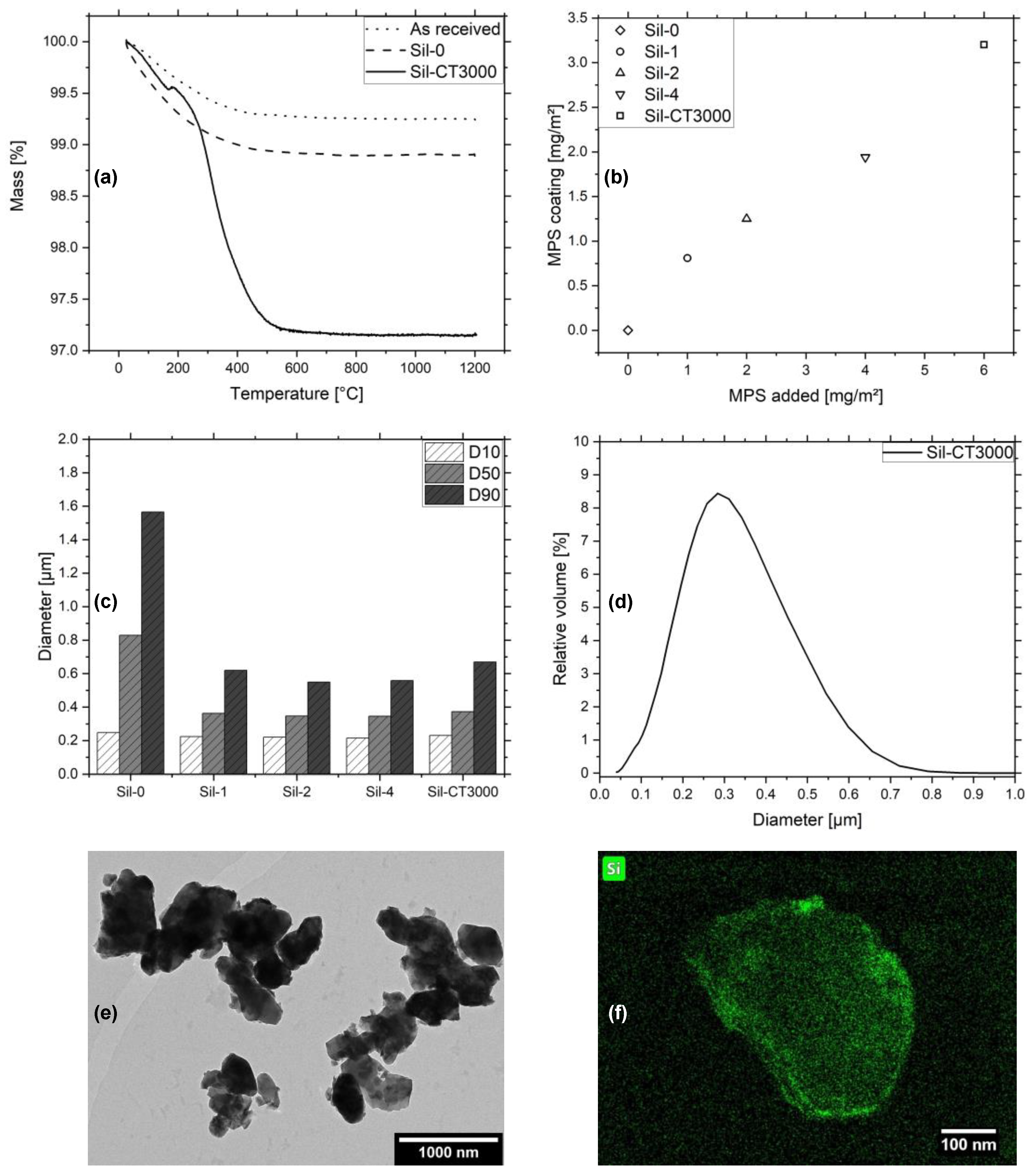
3.1. Ceramic Functionalization
3.2. Ink Solvent
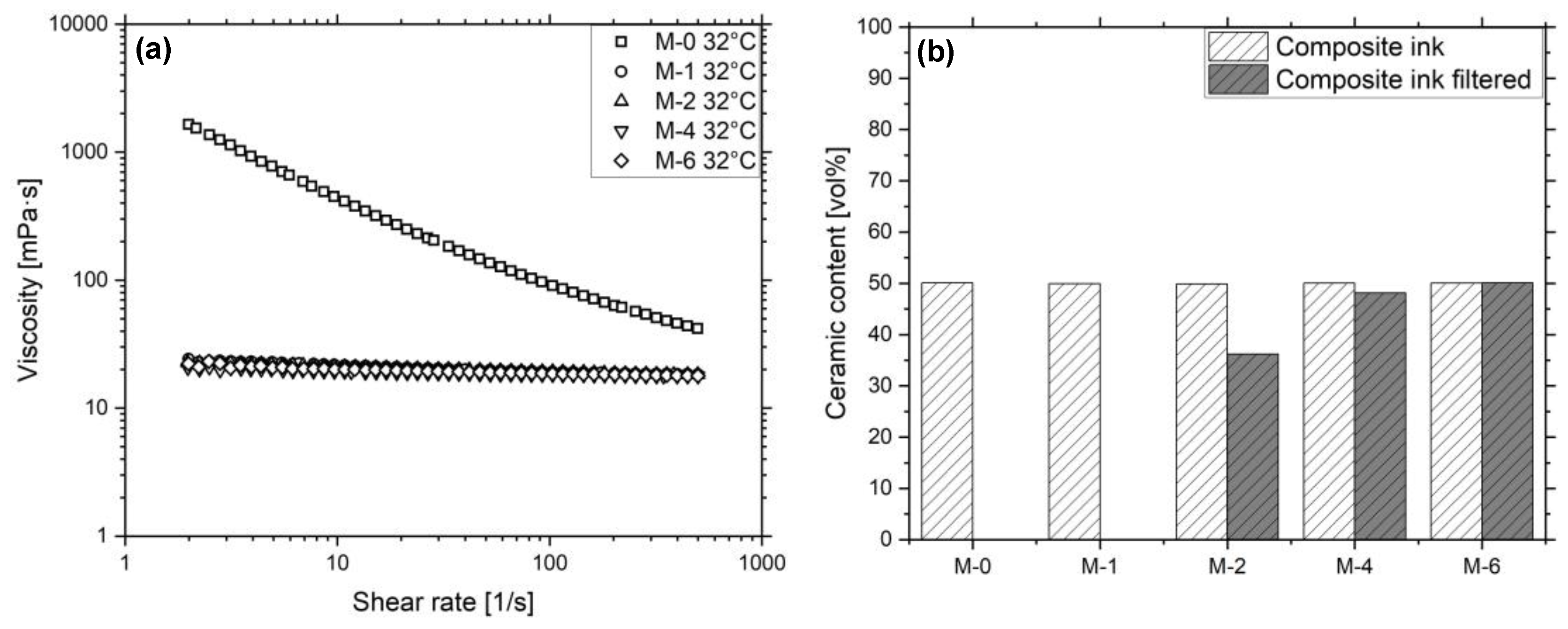
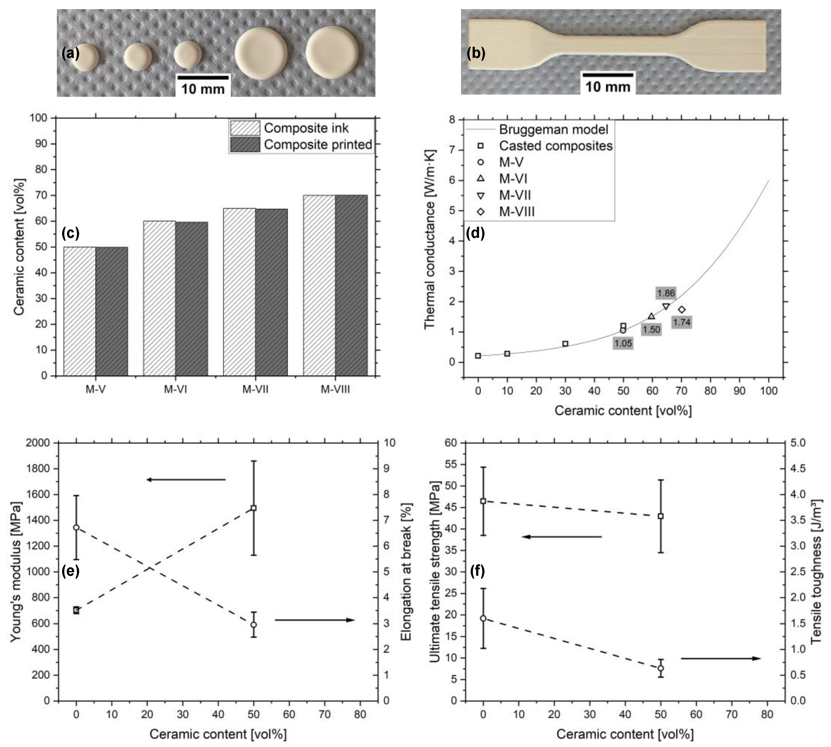
3.3. Ink Ratio
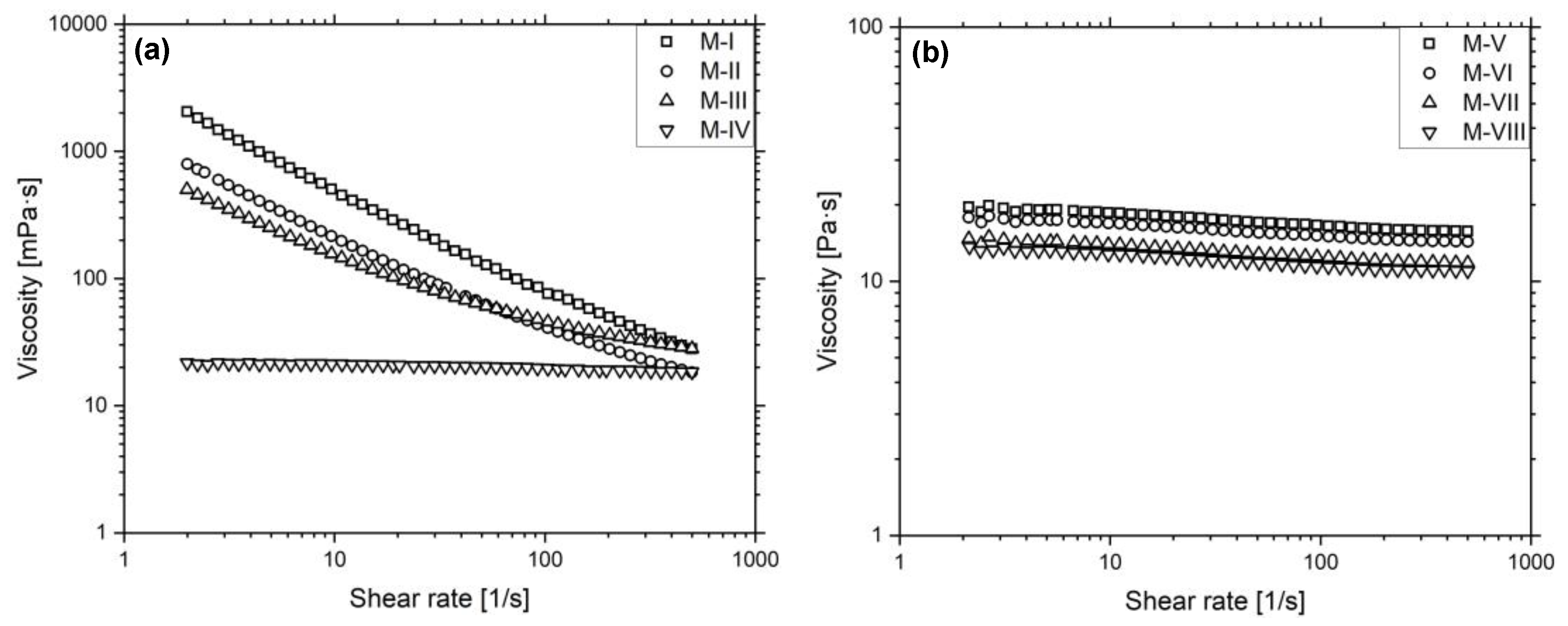
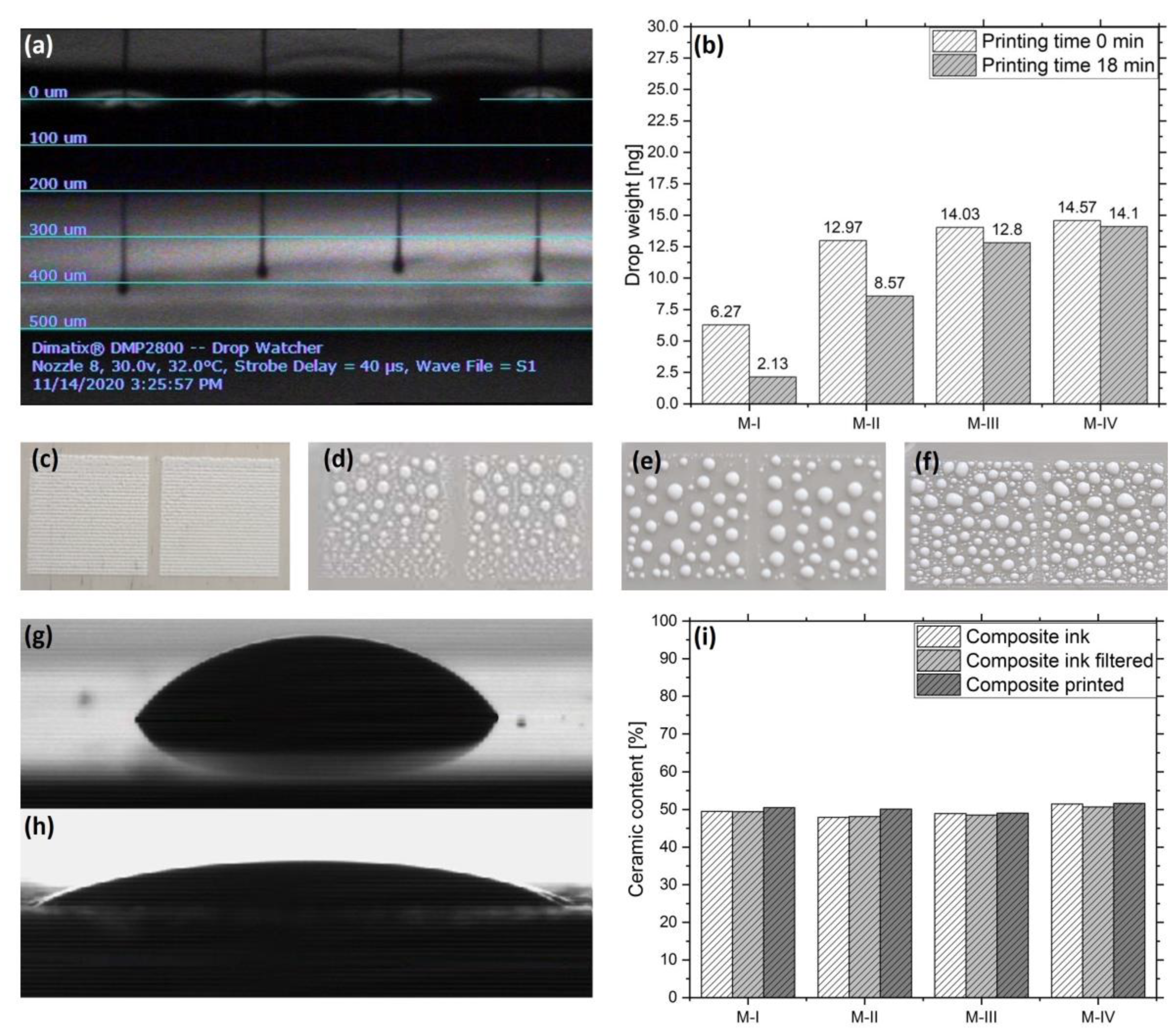
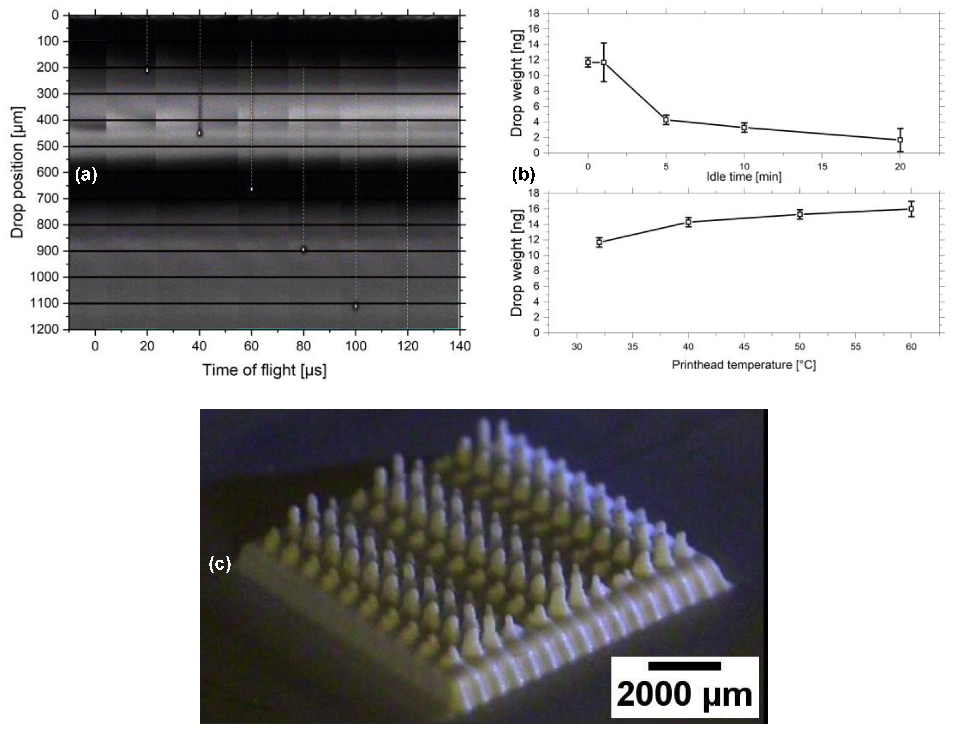
3.4. Ink Characterization
4. Conclusions
Author Contributions
Funding
Acknowledgments
Conflicts of Interest
Appendix A

| Composition | M-0 [wt%] | M-1 [wt%] | M-2 [wt%] | M-4 [wt%] | M-6 [wt%] |
|---|---|---|---|---|---|
| Sil-0 | 49.2 | 0 | 0 | 0 | 0 |
| Sil-1 | 0 | 49.5 | 0 | 0 | 0 |
| Sil-2 | 0 | 0 | 49.6 | 0 | 0 |
| Sil-4 | 0 | 0 | 0 | 49.9 | 0 |
| Sil-CT3000 | 0 | 0 | 0 | 0 | 50.5 |
| DEGMEE | 37.0 | 37.1 | 37.1 | 37.1 | 37.1 |
| Genomer 4247 | 13.2 | 12.9 | 12.8 | 12.6 | 12.0 |
| TPO | 0.40 | 0.39 | 0.38 | 0.38 | 0.36 |
| DLP | 0.13 | 0.13 | 0.13 | 0.13 | 0.12 |
| Composition | M-I [wt% (vol%)] | M-II [wt% (vol%)] | M-III [wt% (vol%)] | M-IV [wt% (vol%)] |
|---|---|---|---|---|
| Sil-TEC170 | 51.0 (20.3) | 51 (21.7) | 51.6 (21.9) | 51.6 (22.4) |
| MPS | 1.2 (1.7) | 1.2 (1.9) | 0 (0) | 0 (0) |
| HexylAc | 36.4 (62.4) | 0 (0) | 0 (0) | 0 (0) |
| PGMMEA | 0 (0) | 36.4 (59.8) | 0 (0) | 0 (0) |
| DPGMME | 0 (0) | 0 (0) | 36.9 (61.5) | 0 (0) |
| DEGMEE | 0 (0) | 0 (0) | 0 (0) | 36.9 (60.5) |
| Genomer 4247 | 11.0 (14.9) | 11.0 (15.9) | 11.1 (16.0) | 11.1 (16.4) |
| TPO | 0.33 (0.44) | 0.33 (0.47) | 0.33 (0.47) | 0.33 (0.48) |
| DLP | 0.11 (0.18) | 0.11 (0.19) | 0.11 (0.19) | 0.11 (0.20) |
| Composition | M-V [wt% (vol%)] | M-VI [wt% (vol%)] | M-VII [wt% (vol%)] | M-VIII [wt% (vol%)] |
|---|---|---|---|---|
| Sil-CT3000 | 50.9 (22.2) | 51.1 (22.2) | 51.22 (22.16) | 51.3 (22.2) |
| DEGMEE | 36.5 (59.5) | 40.9 (66.3) | 42.5 (68.8) | 44.0 (71.1) |
| Genomer 4247 | 12.1 (17.6) | 7.7 (11.1) | 6.0 (8.7) | 4.5 (6.5) |
| TPO | 0.36 (0.52) | 0.23 (0.33) | 0.18 (0.26) | 0.14 (0.19) |
| DLP | 0.12 (0.22) | 0.08 (0.14) | 0.06 (0.11) | 0.05 (0.08) |
| Composition | C-0 [wt% (vol%)] | C-10 [wt% (vol%)] | C-30 [wt% (vol%)] | C-50 [wt% (vol%)] |
|---|---|---|---|---|
| Sil-CT3000 | 0 (0) | 24.9 (8.4) | 51.2 (25.8) | 74.5 (43.4) |
| 2-propanol | 0 (0) | 14.8 (23.7) | 10.7 (23.3) | 8.5 (23.6) |
| Genomer 4247 | 96.2 (96.0) | 58.0 (65.2) | 31.8 (48.8) | 16.3 (31.7) |
| TPO | 2.88 (2.83) | 1.74 (1.94) | 0.95 (1.45) | 0.49 (0.94) |
| DLP | 0.96 (1.16) | 0.58 (0.80) | 0.32 (0.60) | 0.16 (0.39) |


References
- Dämmer, G.; Gablenz, S.; Hildebrandt, A.; Major, Z. Design of an Additively Manufacturable Multi-Material Light-Weight Gripper with integrated Bellows Actuators. Adv. Sci. Technol. Eng. Syst. J. 2019, 4, 23–33. [Google Scholar] [CrossRef] [Green Version]
- Dämmer, G.; Lackner, M.; Laicher, S.; Neumann, R.; Major, Z. Design of an Inkjet-Printed Rotary Bellows Actuator and Simulation of its Time-Dependent Deformation Behavior. Front. Robot. AI 2021, 8, 160. [Google Scholar] [CrossRef]
- Vaezi, M.; Seitz, H.; Yang, S. A review on 3D micro-additive manufacturing technologies. Int. J. Adv. Manuf. Technol. 2013, 67, 1721–1754. [Google Scholar] [CrossRef]
- Yang, H.; Lim, J.C.; Liu, Y.; Qi, X.; Yap, Y.L.; Dikshit, V.; Yeong, W.Y.; Wei, J. Performance evaluation of ProJet multi-material jetting 3D printer. Virtual Phys. Prototyp. 2017, 12, 95–103. [Google Scholar] [CrossRef]
- Cazón, A.; Morer, P.; Matey, L. PolyJet technology for product prototyping: Tensile strength and surface roughness properties. Proc. Inst. Mech. Eng. Part B J. Eng. Manuf. 2014, 228, 1664–1675. [Google Scholar] [CrossRef]
- Yuan, J.; Chen, C.; Yao, D.; Chen, G. 3D Printing of Oil Paintings Based on Material Jetting and Its Reduction of Staircase Effect. Polymers (Basel) 2020, 12, 2536. [Google Scholar] [CrossRef]
- Salmi, M.; Paloheimo, K.-S.; Tuomi, J.; Wolff, J.; Mäkitie, A. Accuracy of medical models made by additive manufacturing (rapid manufacturing). J. Cranio-Maxillofac. Surg. 2013, 41, 603–609. [Google Scholar] [CrossRef]
- Zammit, D.; Safran, T.; Ponnudurai, N.; Jaberi, M.; Chen, L.; Noel, G.; Gilardino, M. Step-Specific Simulation: The Utility of 3D Printing for the Fabrication of a Low-Cost, Learning Needs-Based Rhinoplasty Simulator. Aesthetic Surg. J. 2020, 40. [Google Scholar] [CrossRef] [PubMed]
- Mendible, G.A.; Rulander, J.A.; Johnston, S.P. Comparative study of rapid and conventional tooling for plastics injection molding. Rapid Prototyp. J. 2017, 23, 344–352. [Google Scholar] [CrossRef]
- Tappa, K.; Jammalamadaka, U. Novel Biomaterials Used in Medical 3D Printing Techniques. J. Funct. Biomater. 2018, 9, 22. [Google Scholar] [CrossRef] [PubMed] [Green Version]
- Gouzman, I.; Grossman, E.; Verker, R.; Atar, N.; Bolker, A.; Eliaz, N. Advances in Polyimide-Based Materials for Space Applications. Adv. Mater. 2019, 31, 1807738. [Google Scholar] [CrossRef] [PubMed]
- Eufracio Aguilera, A.F.; Nagarajan, B.; Fleck, B.A.; Qureshi, A.J. Ferromagnetic particle structuring in material jetting—Manufacturing control system and software development. Procedia Manuf. 2019, 34, 545–551. [Google Scholar] [CrossRef]
- Kamyshny, A.; Magdassi, S. Conductive Nanomaterials for Printed Electronics. Small 2014, 10, 3515–3535. [Google Scholar] [CrossRef]
- Zhang, F.; Saleh, E.; Vaithilingam, J.; Li, Y.; Tuck, C.J.; Hague, R.J.M.; Wildman, R.D.; He, Y. Reactive material jetting of polyimide insulators for complex circuit board design. Addit. Manuf. 2019, 25, 477–484. [Google Scholar] [CrossRef]
- Saleh, E.; Zhang, F.; He, Y.; Vaithilingam, J.; Fernandez, J.L.; Wildman, R.; Ashcroft, I.; Hague, R.; Dickens, P.; Tuck, C. 3D Inkjet Printing of Electronics Using UV Conversion. Adv. Mater. Technol. 2017, 2, 1700134. [Google Scholar] [CrossRef]
- Jabari, E.; Liravi, F.; Davoodi, E.; Lin, L.; Toyserkani, E. High Speed Three-Dimensional Material-Jetting Additive Manufacturing of Viscous Graphene-based Ink with High Electrical Conductivity. Addit. Manuf. 2020, 35, 101330. [Google Scholar] [CrossRef]
- Balandin, A.A.; Ghosh, S.; Bao, W.; Calizo, I.; Teweldebrhan, D.; Miao, F.; Lau, C.N. Superior Thermal Conductivity of Single-Layer Graphene. Nano Lett. 2008, 8, 902–907. [Google Scholar] [CrossRef] [PubMed]
- Lu, L.; Zhang, Z.; Xu, J.; Pan, Y. 3D-printed polymer composites with acoustically assembled multidimensional filler networks for accelerated heat dissipation. Compos. Part B Eng. 2019, 174, 106991. [Google Scholar] [CrossRef]
- MacDonald, E.; Wicker, R. Multiprocess 3D printing for increasing component functionality. Science 2016, 353. [Google Scholar] [CrossRef] [PubMed]
- Bordia, R.K.; Kang, S.-J.L.; Olevsky, E.A. Current understanding and future research directions at the onset of the next century of sintering science and technology. J. Am. Ceram. Soc. 2017, 100, 2314–2352. [Google Scholar] [CrossRef] [Green Version]
- Quill, T.J.; Smith, M.K.; Zhou, T.; Baioumy, M.G.S.; Berenguer, J.P.; Cola, B.A.; Kalaitzidou, K.; Bougher, T.L. Thermal and mechanical properties of 3D printed boron nitride—ABS composites. Appl. Compos. Mater. 2018, 25, 1205–1217. [Google Scholar] [CrossRef]
- Chen, H.; Ginzburg, V.V.; Yang, J.; Yang, Y.; Liu, W.; Huang, Y.; Du, L.; Chen, B. Thermal conductivity of polymer-based composites: Fundamentals and applications. Prog. Polym. Sci. 2016, 59, 41–85. [Google Scholar] [CrossRef]
- Check, C.; Chartoff, R.; Chang, S. Inkjet printing of 3D nano-composites formed by photopolymerization of an acrylate monomer. React. Funct. Polym. 2015, 97, 116–122. [Google Scholar] [CrossRef] [Green Version]
- Saleh, E.; Woolliams, P.; Clarke, B.; Gregory, A.; Greedy, S.; Smartt, C.; Wildman, R.; Ashcroft, I.; Hague, R.; Dickens, P.; et al. 3D inkjet-printed UV-curable inks for multi-functional electromagnetic applications. Addit. Manuf. 2017, 13, 143–148. [Google Scholar] [CrossRef]
- Danu, S. DARSONO MARSONGKO UV-curing of titanium dioxide pigmented epoxy acrylate coating on ceramic tiles. J. Ceram. Soc. Jpn. 2008, 116, 896–903. [Google Scholar] [CrossRef] [Green Version]
- Magdassi, S. The Chemistry of Inkjet Inks; Magdassi, S., Ed.; World Scientific Pub.: Singapore, 2010; ISBN 9789812818218 9812818219. [Google Scholar]
- Derby, B. Additive Manufacture of Ceramics Components by Inkjet Printing. Engineering 2015, 1, 113–123. [Google Scholar] [CrossRef] [Green Version]
- Derby, B. Inkjet printing ceramics: From drops to solid. J. Eur. Ceram. Soc. 2011, 31, 2543–2550. [Google Scholar] [CrossRef]
- Lewis, J.A. Colloidal Processing of Ceramics. J. Am. Ceram. Soc. 2000, 83, 2341–2359. [Google Scholar] [CrossRef]
- Consiglio, R.; Baker, D.R.; Paul, G.; Stanley, H.E. Continuum percolation thresholds for mixtures of spheres of different sizes. Phys. A Stat. Mech. Its Appl. 2003, 319, 49–55. [Google Scholar] [CrossRef]
- Baruch, A.-E.; Bielenki, L.; Regev, O. Thermal conductivity improvement of electrically nonconducting composite materials. Rev. Chem. Eng. 2012, 28, 61–71. [Google Scholar] [CrossRef]
- Bruggeman, D.A.G. Berechnung verschiedener physikalischer Konstanten von heterogenen Substanzen. I. Dielektrizitätskonstanten und Leitfähigkeiten der Mischkörper aus isotropen Substanzen. Ann. Phys. 1935, 416, 636–664. [Google Scholar] [CrossRef]
- Pietrak, K.; Wiśniewski, T.S. A review of models for effective thermal conductivity of composite materials. J. Power Technol. 2014, 95, 14–24. [Google Scholar]
- Tsukuda, R.; Sumimoto, S.; Ozawa, T. Thermal conductivity and heat capacity of ABS resin composites. J. Appl. Polym. Sci. 1997, 63, 1279–1286. [Google Scholar] [CrossRef]
- Ho, C.Y.; Powell, R.W.; Liley, P.E. Thermal conductivity of the elements: A comprehensive review. J. Phys. Chem. Ref. Data Suppl. 1974, 3, 1–796. [Google Scholar]
- Giri, A.; Hopkins, P.E.; Wessel, J.G.; Duda, J.C. Kapitza resistance and the thermal conductivity of amorphous superlattices. J. Appl. Phys. 2015, 118, 165303. [Google Scholar] [CrossRef]
- Chung, H.S.; Hogg, R. The effect of brownian motion on particle size analysis by sedimentation. Powder Technol. 1985, 41, 211–216. [Google Scholar] [CrossRef]
- Sobisch, T.; Lerche, D. Charakterisierung interpartikulärer Kräfte für Fest/Flüssig-Trennverfahren mittels Analytischer Zentrifugation. Chem. Ing. Tech. 2008, 80, 393–397. [Google Scholar] [CrossRef]
- Bourgeat-Lami, E.; Lang, J. Encapsulation of Inorganic Particles by Dispersion Polymerization in Polar Media: 1. Silica Nanoparticles Encapsulated by Polystyrene. J. Colloid Interface Sci. 1998, 197, 293–308. [Google Scholar] [CrossRef] [PubMed]
- Edmondson, S.; Osborne, V.L.; Huck, W.T.S. Polymer brushes via surface-initiated polymerizations. Chem. Soc. Rev. 2004, 33, 14–22. [Google Scholar] [CrossRef] [PubMed]
- Yoo, C.; Lee, C.; Shin, H.; Yeo, D.; Kim, S. Dispersion Optimization of Alumina Slurry with Variation of the Dispersant. J. Nanosci. Nanotechnol. 2019, 19, 1677–1681. [Google Scholar] [CrossRef]
- Arkles, B. Tailoring Surfaces with Silanes. Chemtech 1977, 7, 766–778. [Google Scholar]
- Tanurdjaja, S.; Tallon, C.; Scales, P.J.; Franks, G. V Influence of dispersant size on rheology of non-aqueous ceramic particle suspensions. Adv. Powder Technol. 2011, 22, 476–481. [Google Scholar] [CrossRef]
- De Hazan, Y.; Heinecke, J.; Weber, A.; Graule, T. High solids loading ceramic colloidal dispersions in UV curable media via comb-polyelectrolyte surfactants. J. Colloid Interface Sci. 2009, 337, 66–74. [Google Scholar] [CrossRef]
- Smith, W.O.; Foote, P.D.; Busang, P.F. Packing of Homogeneous Spheres. Phys. Rev. 1929, 34, 1271–1274. [Google Scholar] [CrossRef]
- Rutgers, R. Packing of Spheres. Nature 1962, 193, 465–466. [Google Scholar] [CrossRef]
- Burger, N.; Laachachi, A.; Ferriol, M.; Lutz, M.; Toniazzo, V.; Ruch, D. Review of thermal conductivity in composites: Mechanisms, parameters and theory. Prog. Polym. Sci. 2016, 61, 1–28. [Google Scholar] [CrossRef]
- Fayazfar, H.; Liravi, F.; Ali, U.; Toyserkani, E. Additive manufacturing of high loading concentration zirconia using high-speed drop-on-demand material jetting. Int. J. Adv. Manuf. Technol. 2020, 109, 2733–2746. [Google Scholar] [CrossRef]
- Lee, D.H.; Derby, B. Preparation of PZT suspensions for direct ink jet printing. J. Eur. Ceram. Soc. 2004, 24, 1069–1072. [Google Scholar] [CrossRef]
- Zhao†, X.; Evans, J.R.G.; Edirisinghe, M.J.; Song, J.-H. Direct Ink-Jet Printing of Vertical Walls. J. Am. Ceram. Soc. 2002, 85, 2113–2115. [Google Scholar] [CrossRef]
- Tseng, W.J.; Lin, S.-Y.; Wang, S.-R. Particulate dispersion and freeform fabrication of BaTiO3 thick films via direct inkjet printing. J. Electroceram. 2006, 16, 537–540. [Google Scholar] [CrossRef]
- Kango, S.; Kalia, S.; Celli, A.; Njuguna, J.; Habibi, Y.; Kumar, R. Surface modification of inorganic nanoparticles for development of organic–inorganic nanocomposites—A review. Prog. Polym. Sci. 2013, 38, 1232–1261. [Google Scholar] [CrossRef]
- Sabzi, M.; Mirabedini, S.M.; Zohuriaan-Mehr, J.; Atai, M. Surface modification of TiO2 nano-particles with silane coupling agent and investigation of its effect on the properties of polyurethane composite coating. Prog. Org. Coat. 2009, 65, 222–228. [Google Scholar] [CrossRef]
- Nejad, S.J.J. A review on modeling of the thermal conductivity of polymeric nanocomposites. E-Polymers 2012, 12, 25. [Google Scholar] [CrossRef]
- Tasic, S.; Bozic, B.; Dunjic, B. Synthesis of new hyperbranched urethane-acrylates and their evaluation in UV-curable coatings. Prog. Org. Coat. 2004, 51, 320–327. [Google Scholar] [CrossRef]
- Stepto, R.F.T.; Cail, J.I.; Taylor, D.J.R. Polymer networks: Principles of formation, structure and properties. Polim. Polym. 2000, 45, 455–464. [Google Scholar] [CrossRef]
- Andrzejewska, E. Photopolymerization kinetics of multifunctional monomers. Prog. Polym. Sci. 2001, 26, 605–665. [Google Scholar] [CrossRef]
- van Oss, C.J.; Giese, R.F.; Costanzo, P.M. DLVO and Non-DLVO Interactions in Hectorite. Clays Clay Miner. 1990, 38, 151–159. [Google Scholar] [CrossRef]
- Paik, U.; Hackley, V.A.; Choi, S.-C.; Jung, Y.-G. The effect of electrostatic repulsive forces on the stability of BaTiO3 particles suspended in non-aqueous media. Colloids Surf. A Physicochem. Eng. Asp. 1998, 135, 77–88. [Google Scholar] [CrossRef]
- Balazs, A.C.; Emrick, T.; Russell, T.P. Nanoparticle Polymer Composites: Where Two Small Worlds Meet. Science 2006, 314, 1107–1110. [Google Scholar] [CrossRef]
- Fu, S.-Y.; Feng, X.-Q.; Lauke, B.; Mai, Y.-W. Effects of particle size, particle/matrix interface adhesion and particle loading on mechanical properties of particulate–polymer composites. Compos. Part B Eng. 2008, 39, 933–961. [Google Scholar] [CrossRef]
- Graf, D.; Burchard, S.; Crespo, J.; Megnin, C.; Gutsch, S.; Zacharias, M.; Hanemann, T. Influence of Al2O3 Nanoparticle Addition on a UV Cured Polyacrylate for 3D Inkjet Printing. Polymers (Basel) 2019, 11, 633. [Google Scholar] [CrossRef] [PubMed] [Green Version]
- Graf, D.; Qazzazie, A.; Hanemann, T. Investigations on the Processing of Ceramic Filled Inks for 3D InkJet Printing. Materials (Basel) 2020, 13, 2587. [Google Scholar] [CrossRef] [PubMed]


| Chemical Name | CAS. No. | Supplier |
|---|---|---|
| 3-(trimethoxysilyl)propylmethacrylate | 2530-85-0 | Merck KGaA |
| Ethanol | 64-17-5 | Carl Roth Gmbh |
| 2-propanol | 67-63-0 | Carl Roth Gmbh |
| Genomer 4247 | - | Rahn AG |
| Diphenyl(2,4,6-trimethylbenzoyl)phosphine oxide | 75980-60-8 | TCI CO., LTD. |
| Dilauroyl peroxide | 105-74-8 | Merck KGaA |
| Hexyl acetate | 142-92-7 | Merck KGaA |
| Propylene glycol monomethyl ether acetate | 108-65-6 | Merck KGaA |
| Dipropylene glycol monomethyl ether | 34590-94-8 | Merck KGaA |
| Diethylene glycol monoethyl ether | 111-90-0 | Carl Roth Gmbh |
| Diiodomethane | 75-11-6 | Merck KGaA |
| Product Name | Chemical Name | SSA (m2/g) | Supplier |
|---|---|---|---|
| CT3000SG | Al2O3 | 6.42 | Almatis GmbH |
| TEC170 1 | Al2O3 | 8.71 | Tecnan |
| Sample Name | MPS (g) | MPS (mg/m2) |
|---|---|---|
| Sil-0 | 0 | 0 |
| Sil-1 | 0.32 | 1 |
| Sil-2 | 0.64 | 2 |
| Sil-4 | 1.28 | 4 |
| Sil-CT3000 | 1.94 | 6 |
| Surface Tension [mN/m] | Viscosity at 32 °C [mPa·s] | Viscosity at 60 °C [mPa·s] | |
|---|---|---|---|
| Genomer 4247 | 38.4 ± 1.7 | 4223.0 ± 145.1 | 3231.0 ± 66.4 |
| HexylAc | 24.6 ± 0.4 | 1.4 ± 0.1 | 1.1 ± 0.0 |
| PGMMEA | 28.1 ± 1.3 | 1.7 ± 0.0 | 1.2 ± 0.1 |
| DPGMME | 30.3 ± 0.1 | 3.6 ± 0.0 | 2.0 ± 0.0 |
| DEGMEE | 34.8 ± 1.3 | 4.2 ± 0.1 | 2.3 ± 0.1 |
| M-I | 16.1 ± 0.8 | 27.9 ± 2.1 | 24.2 ± 2.4 |
| M-II | 27.9 ± 1.9 | 18.3 ± 1.8 | 18.4 ± 0.7 |
| M-III | 30.1 ± 0.9 | 28.1 ± 0.6 | 18.8 ± 1.2 |
| M-IV | 31.7 ± 0.2 | 18.4 ± 0.1 | 9.0 ± 0.1 |
| M-V | 31.1 ± 0.2 | 15.7 ± 0.1 | 7.7 ± 0.0 |
| M-VI | 32.3 ± 0.5 | 14.3 ± 0.1 | 7.0 ± 0.1 |
| M-VII | 33.0 ± 0.1 | 11.8 ± 0.1 | 6.4 ± 0.1 |
| M-VIII | 32.3 ± 0.2 | 11.0 ± 0.0 | 5.9 ± 0.0 |
Publisher’s Note: MDPI stays neutral with regard to jurisdictional claims in published maps and institutional affiliations. |
© 2021 by the authors. Licensee MDPI, Basel, Switzerland. This article is an open access article distributed under the terms and conditions of the Creative Commons Attribution (CC BY) license (https://creativecommons.org/licenses/by/4.0/).
Share and Cite
Graf, D.; Jung, J.; Hanemann, T. Formulation of a Ceramic Ink for 3D Inkjet Printing. Micromachines 2021, 12, 1136. https://doi.org/10.3390/mi12091136
Graf D, Jung J, Hanemann T. Formulation of a Ceramic Ink for 3D Inkjet Printing. Micromachines. 2021; 12(9):1136. https://doi.org/10.3390/mi12091136
Chicago/Turabian StyleGraf, Dennis, Judith Jung, and Thomas Hanemann. 2021. "Formulation of a Ceramic Ink for 3D Inkjet Printing" Micromachines 12, no. 9: 1136. https://doi.org/10.3390/mi12091136