
Air-Gap Interrogation of Surface Plasmon Resonance in Otto Configuration


Abstract
:1. Introduction
2. Otto Configuration with Multiple Air-Gaps
2.1. Design
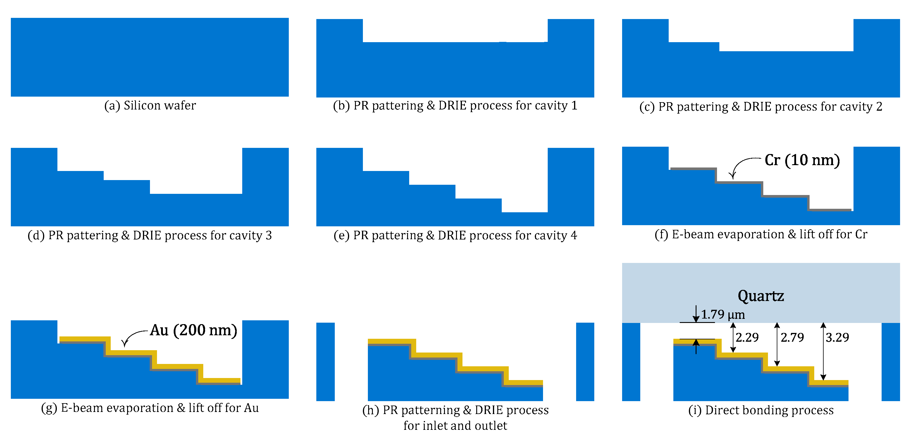
2.2. Fabrication
2.3. Measurement and Results
3. Air-Gap Interrogation of Otto SPR System Using a Piezoactuator
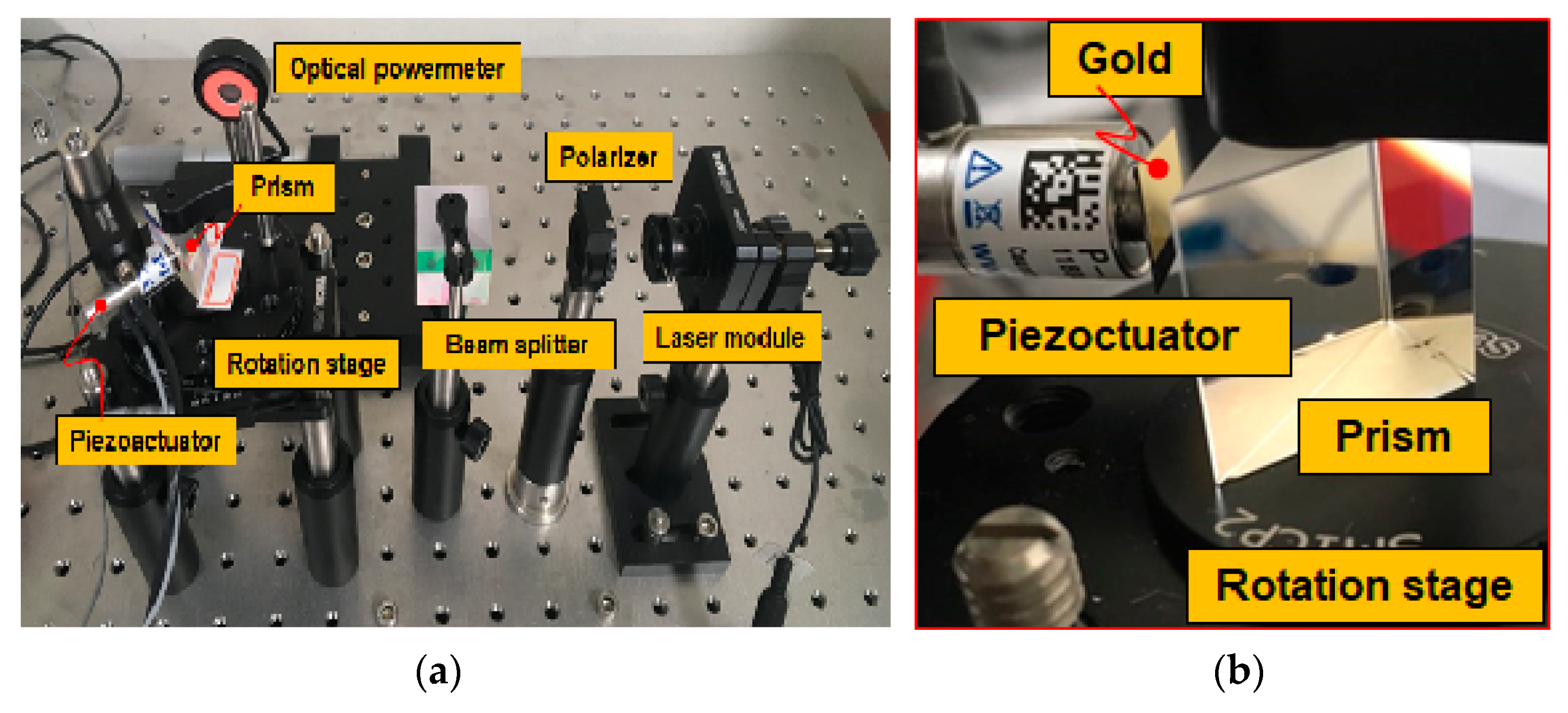
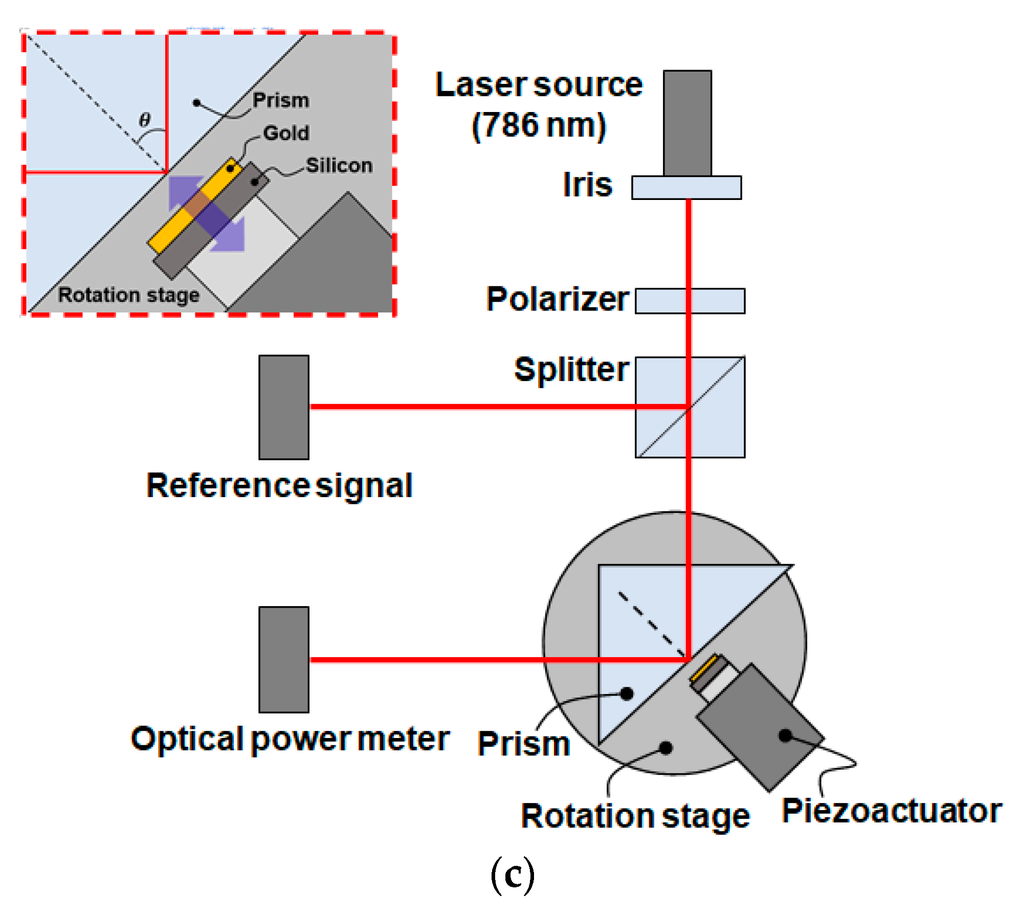
3.1. Otto Configuration-Based SPR System Using a Piezoactuator
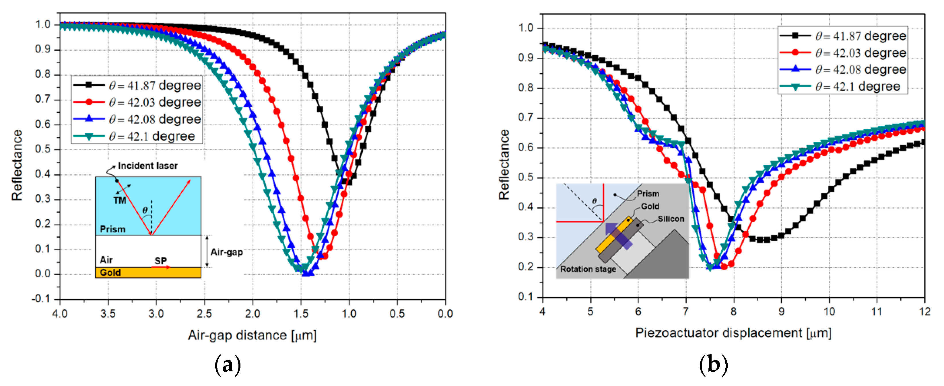
3.2. SPR Characteristics with Air-Gap Variation
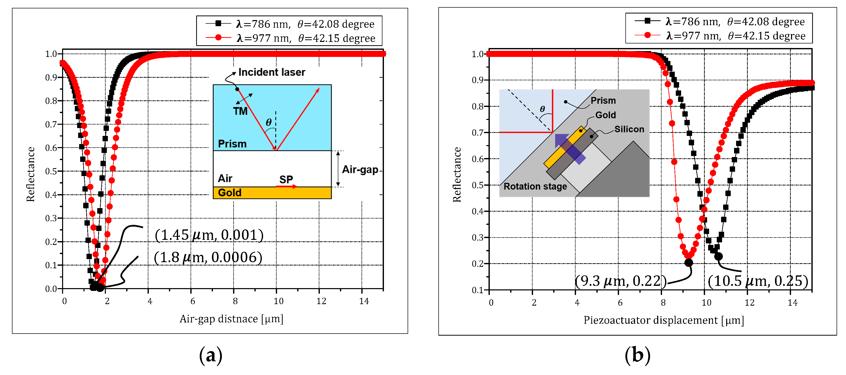
3.3. SPR Characteristics with Air-Gap and Wavlength Variation
4. Conclusions
Author Contributions
Funding
Conflicts of Interest
References
- Paliwal, A.; Sharma, A.; Tomar, M.; Gupta, V. Room temperature detection of NO2 gas using optical sensor based on surface plasmon resonance technique. Sens. Actuators B Chem. 2015, 216, 497–503. [Google Scholar] [CrossRef]
- Paliwal, A.; Sharma, A.; Tomar, M.; Gupta, V. Surface plasmon resonance study on the optical sensing properties of tin oxide (SnO2) films to NH3gas. J. Appl. Phys. 2016, 119, 164502. [Google Scholar] [CrossRef]
- Michel, D.; Xiao, F.; Alameh, K. A compact, flexible fiber-optic Surface Plasmon Resonance sensor with changeable sensor chips. Sens. Actuators B Chem. 2017, 246, 258–261. [Google Scholar] [CrossRef]
- Srivastava, T.; Jha, R. Black Phosphorus: A New Platform for Gaseous Sensing Based on Surface Plasmon Resonance. IEEE Photon. Technol. Lett. 2018, 30, 319–322. [Google Scholar] [CrossRef]
- Wang, D.; Loo, J.F.C.; Chen, J.; Yam, Y.; Chen, S.-C.; He, H.; Kong, S.K.; Ho, H.P. Recent Advances in Surface Plasmon Resonance Imaging Sensors. Sensors 2019, 19, 1266. [Google Scholar] [CrossRef] [PubMed] [Green Version]
- Wang, X.-M.; Zhao, C.-L.; Wang, Y.-R.; Shen, C.-Y.; Dong, X.-Y. A Highly Sensitive Fibre-Optic Nano-Displacement Sensor Based on Surface Plasmon Resonance. J. Lightwave Technol. 2016, 34, 2324–2330. [Google Scholar] [CrossRef]
- Wei, Y.; Wu, P.; Zhu, Z.; Liu, L.; Liu, C.; Hu, J.; Wang, S.; Zhang, Y. Surface-Plasmon-Resonance-Based Optical-Fiber Micro-Displacement Sensor with Temperature Compensation. Sensors 2018, 18, 3210. [Google Scholar] [CrossRef] [PubMed] [Green Version]
- Neto, J.M.; Cavalcanti, G.O.; Llamas-Garro, I.; Kim, J.M.; Fontana, E. Open Otto chip as an SPR pressure transducer. In Proceedings of the 2016 URSI Asia-Pacific Radio Science Conference (URSI AP-RASC), Seoul, Korea, 21–25 August 2016; pp. 1722–1723. [Google Scholar]
- Kretschmann, E.; Raether, H. Radiative decay of non-radiative surface plasmons excited by light. Z. Naturforsch. 1968, 23A, 2135–2136. [Google Scholar] [CrossRef]
- Otto, A. Excitation of nonradiative surface plasma waves in silver by the method of frustrated total reflection. Z. Phys. A 1968, 216, 398–410. [Google Scholar] [CrossRef]
- Fontana, E.; Kim, J.; Llamas-Garro, I.; Cavalcanti, G.O. Microfabricated Otto Chip Device for Surface Plasmon Resonance Based Optical Sensing. Appl. Opt. 2015, 54, 9200–9204. [Google Scholar] [CrossRef] [PubMed]
- Nuster, R.; Paltauf, G.; Burgholzer, P. Comparison of surface plasmon resonance devices for acoustic wave detection in liquid. Opt. Express 2007, 15, 6087–6095. [Google Scholar] [CrossRef] [PubMed]
- Akowuah, E.K.; Gorman, T.; Haxha, S. Design and optimization of a novel surface plasmon resonance biosensor based on Otto configuration. Opt. Express 2009, 17, 23511–23521. [Google Scholar] [CrossRef] [PubMed] [Green Version]
- Xiang, Y.; Zhu, J.; Wu, L.; You, Q.; Ruan, B.; Dai, X. Highly Sensitive Terahertz Gas Sensor Based on Surface Plasmon Resonance with Graphene. IEEE Photon. J. 2017, 10, 1–7. [Google Scholar] [CrossRef]
- Yao, H.; Zhong, S. High-mode spoof SPP of periodic metal grooves for ultra-sensitive terahertz sensing. Opt. Express 2014, 22, 25149–25160. [Google Scholar] [CrossRef] [PubMed] [Green Version]
- Huang, Y.; Zhong, S.; Yao, H.; Cui, D. Tunable Terahertz Plasmonic Sensor Based on Graphene/Insulator Stacks. IEEE Photon. J. 2017, 9, 1–10. [Google Scholar] [CrossRef]
- Li, L.; Huang, T.; Zhao, X.; Wu, X.; Cheng, Z. Highly Sensitive SPR Sensor Based on Hybrid Coupling Between Plasmon and Photonic Mode. IEEE Photon. Technol. Lett. 2018, 30, 1364–1367. [Google Scholar] [CrossRef]
- Sopko, I.M.; Knyazev, G.A. Plasmonic enhancement of mid- and far-infrared acousto-optic interaction. Appl. Opt. 2018, 57, C42–C48. [Google Scholar] [CrossRef] [PubMed]
- Fontana, E.; Pantell, R.H. Characterization of multilayer rough surfaces by use of surface-plasmon spectroscopy. Phys. Rev. B 1988, 37, 3164–3182. [Google Scholar] [CrossRef] [PubMed]
- Boruah, R.; Mohanta, D.; Choudhury, A.; Nath, P.; Ahmed, G.A. Surface Plasmon Resonance-Based Protein Bio-Sensing Using a Kretschmann Configured Double Prism Arrangement. IEEE Sensors J. 2015, 15, 6791–6796. [Google Scholar] [CrossRef]


| Type | Kretschmann | Otto |
|---|---|---|
| Wavelength | Visible range | Visible and IR range |
| Structure | Simple | Complex |
| Design parameter | Refractive index, Metal thickness (<100 nm) | Refractive index, Air-gap thickness (>1 μm) |
| Characteristics Tunability | Low | High |
| Influence of Adhesion layer | High | Low |
| Incident Angle (Degree) | 41.87 | 42.03 | 42.08 | 42.1 |
|---|---|---|---|---|
| FWHM of measurement (μm) | 4.05 | 1.2 | 1.05 | 0.9 |
| FWHM of simulation (μm) | 0.7 | 0.25 | 0.05 | 0.15 |
Publisher’s Note: MDPI stays neutral with regard to jurisdictional claims in published maps and institutional affiliations. |
© 2021 by the authors. Licensee MDPI, Basel, Switzerland. This article is an open access article distributed under the terms and conditions of the Creative Commons Attribution (CC BY) license (https://creativecommons.org/licenses/by/4.0/).
Share and Cite
Lee, Y.; Kim, J.; Sim, S.; Llamas-Garro, I.; Kim, J. Air-Gap Interrogation of Surface Plasmon Resonance in Otto Configuration. Micromachines 2021, 12, 998. https://doi.org/10.3390/mi12080998
Lee Y, Kim J, Sim S, Llamas-Garro I, Kim J. Air-Gap Interrogation of Surface Plasmon Resonance in Otto Configuration. Micromachines. 2021; 12(8):998. https://doi.org/10.3390/mi12080998
Chicago/Turabian StyleLee, Yeonsu, Jiwon Kim, Sungmin Sim, Ignacio Llamas-Garro, and Jungmu Kim. 2021. "Air-Gap Interrogation of Surface Plasmon Resonance in Otto Configuration" Micromachines 12, no. 8: 998. https://doi.org/10.3390/mi12080998