
Simulation-Based and Experimental Investigation of Micro End Mills with Wiper Geometry


Abstract
:
1. Introduction
Design Approach for Hard Micromachining of Tool Steels
2. Materials and Methods
2.1. Material Removal Simulation
2.2. Simulative Setup
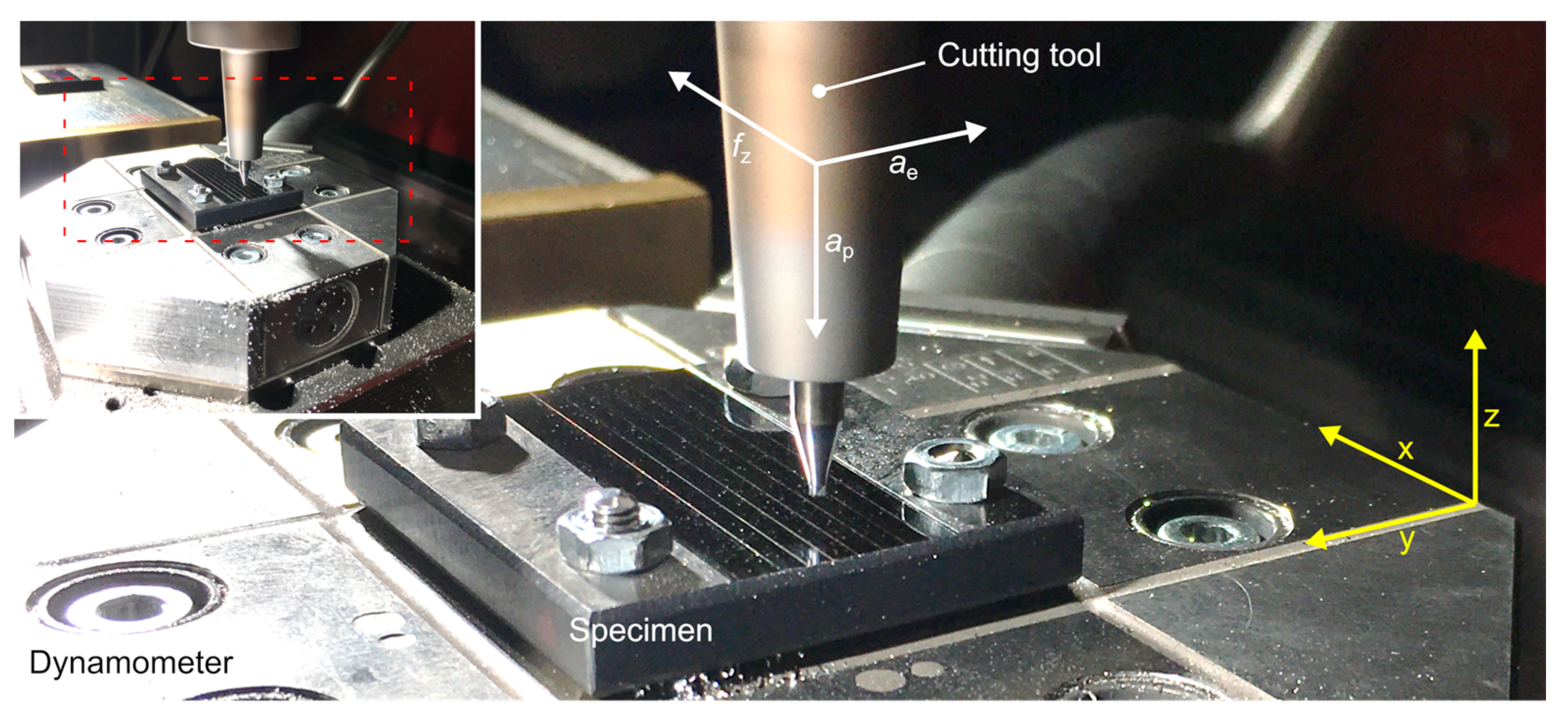
2.3. Experimental Setup
2.4. Specimen Material for Experimental Investigation
2.5. Design of Experiments
3. Results and Discussion
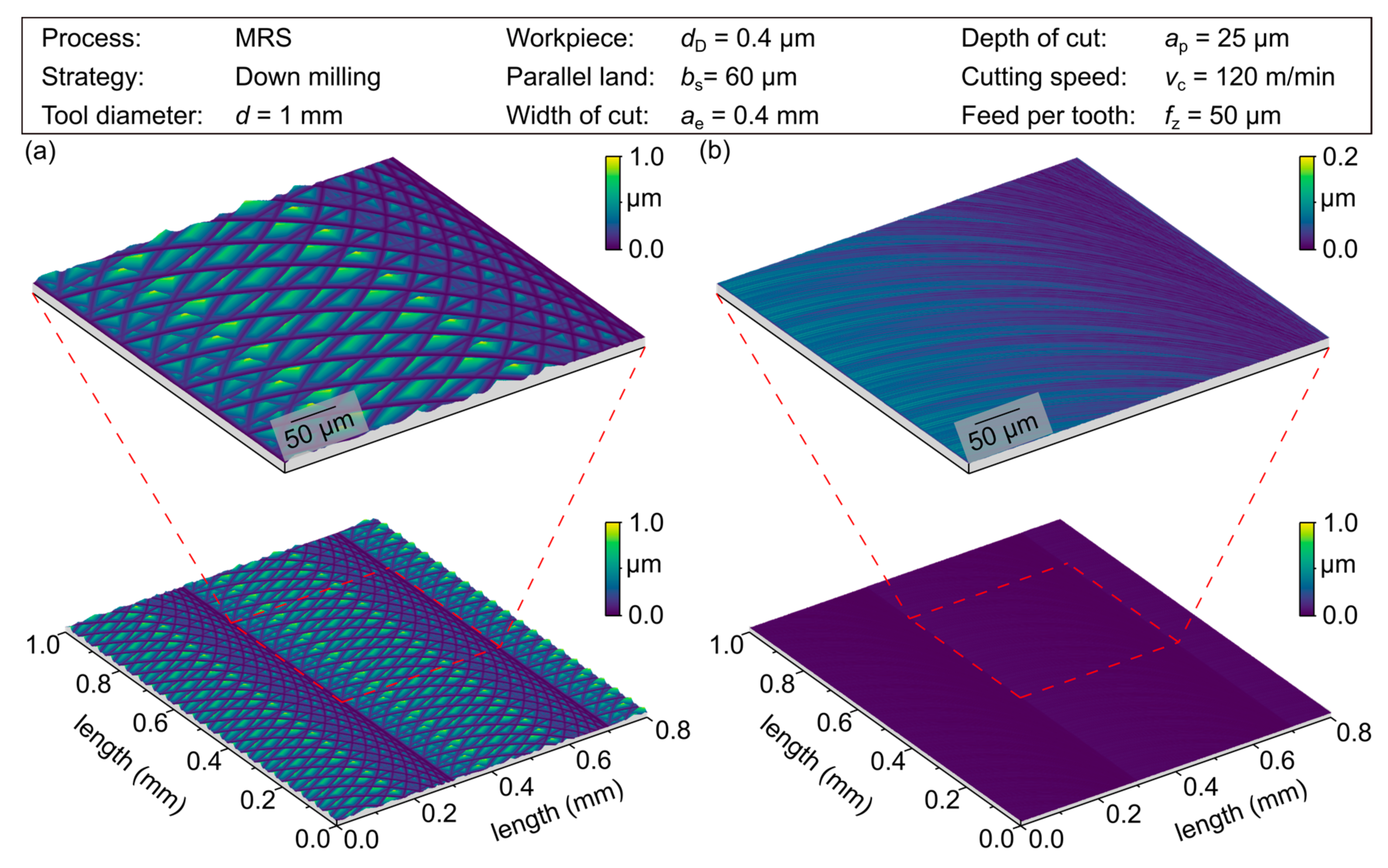
3.1. Material Removal Simulation
3.2. Experimental Investigations
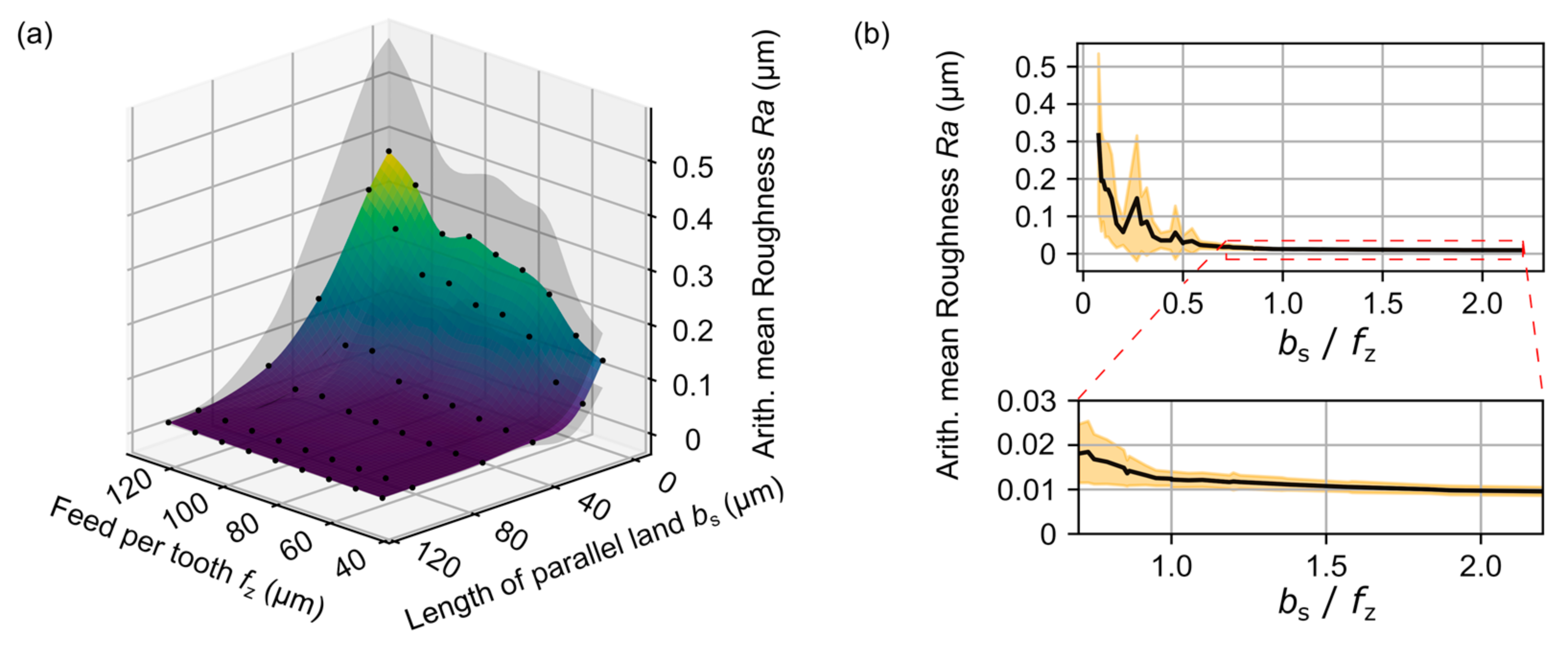
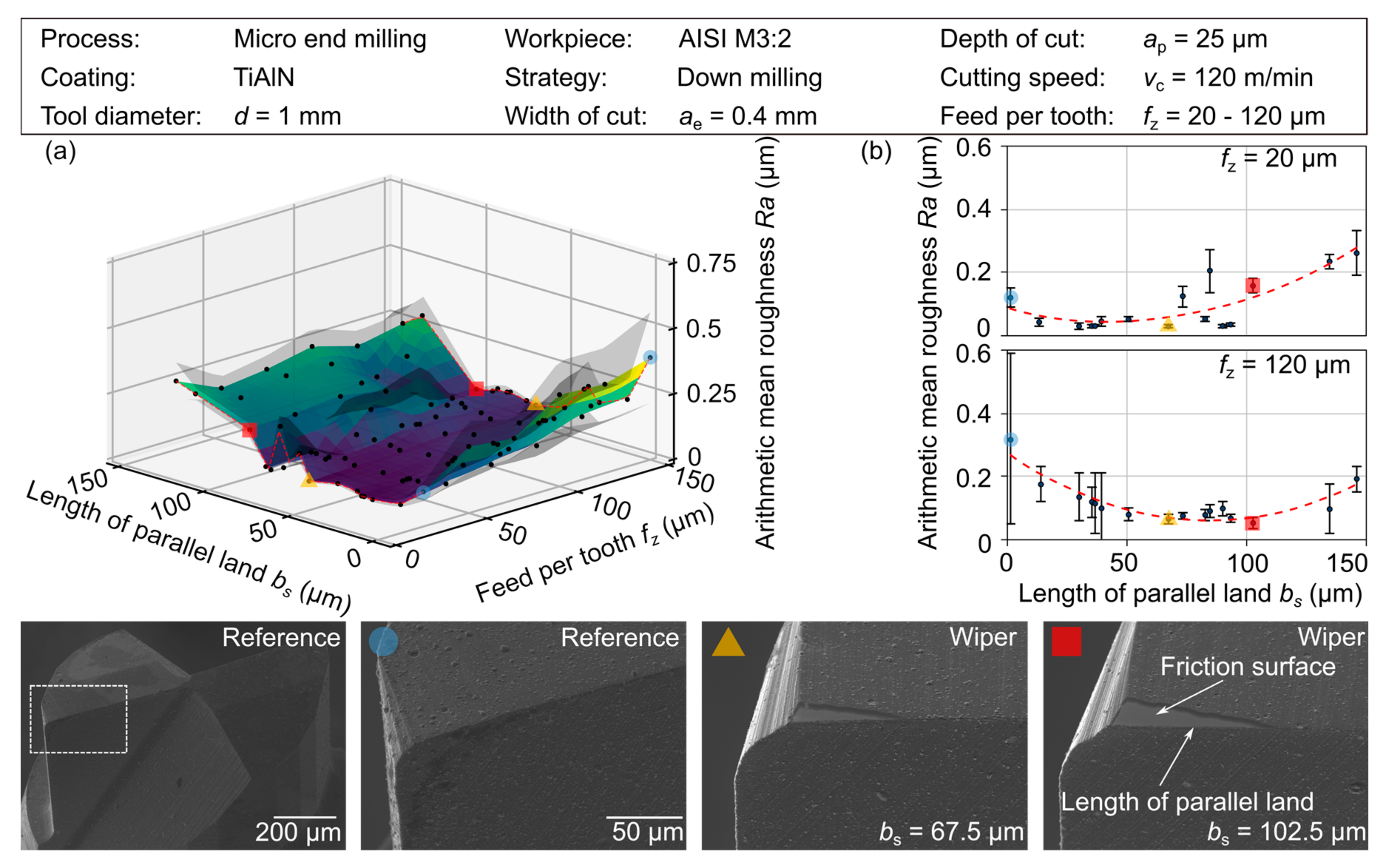
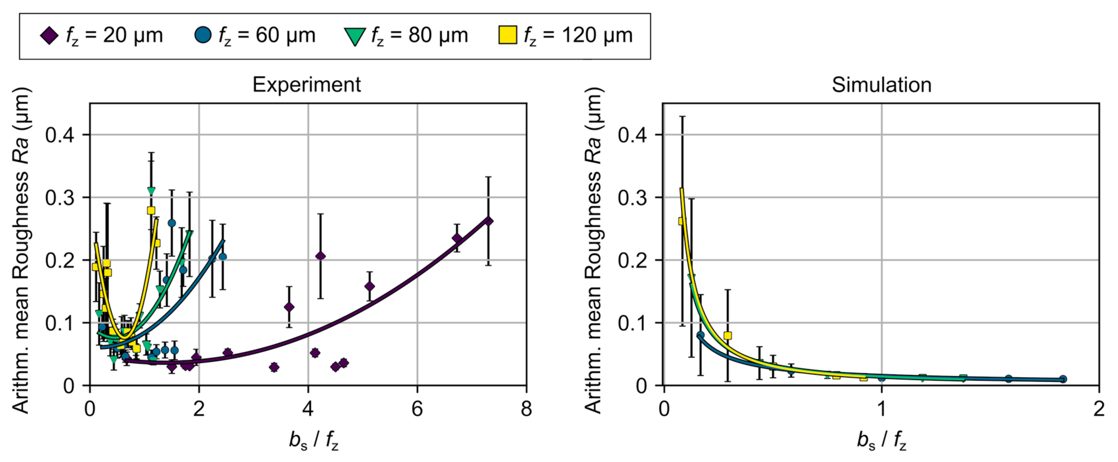
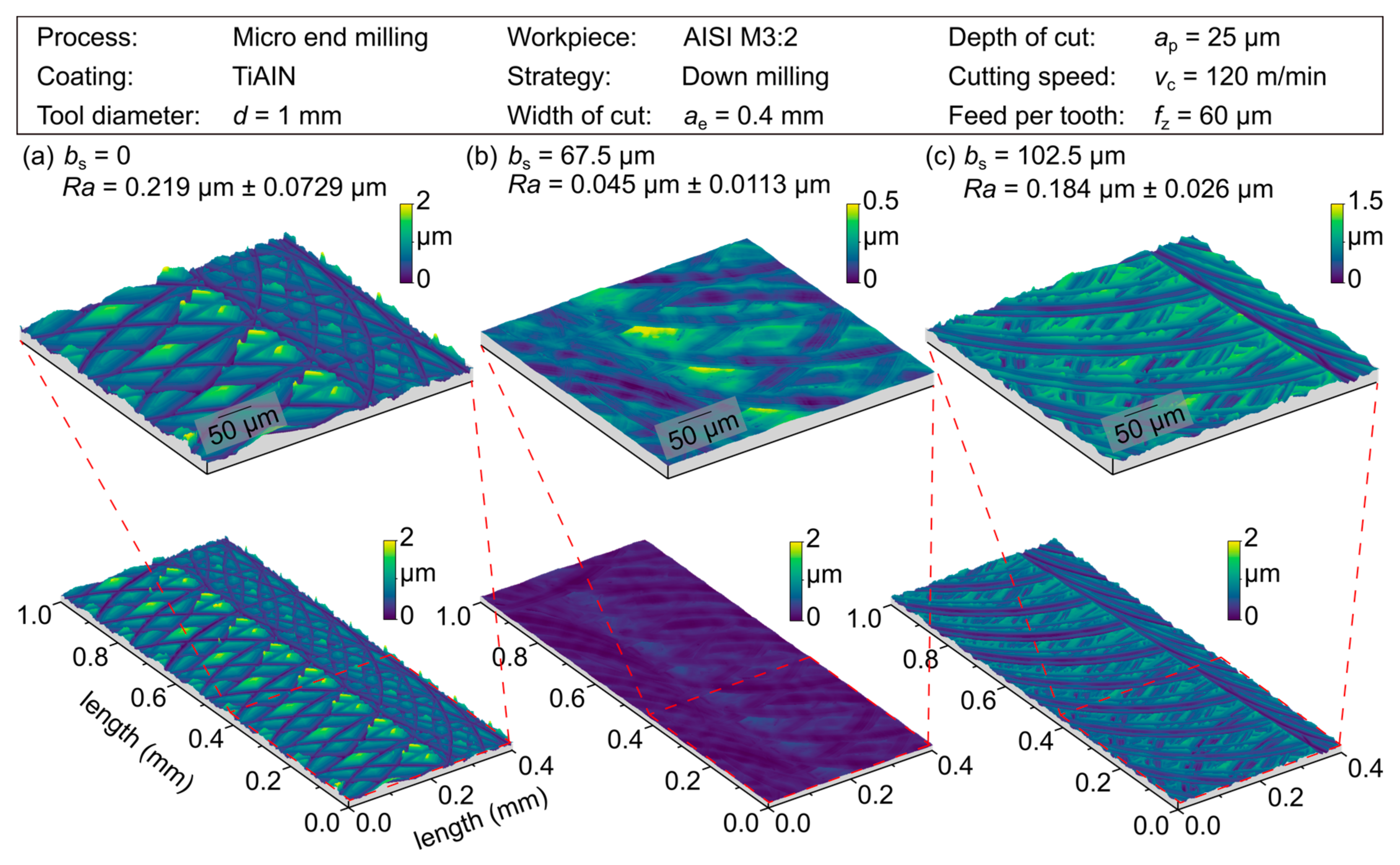
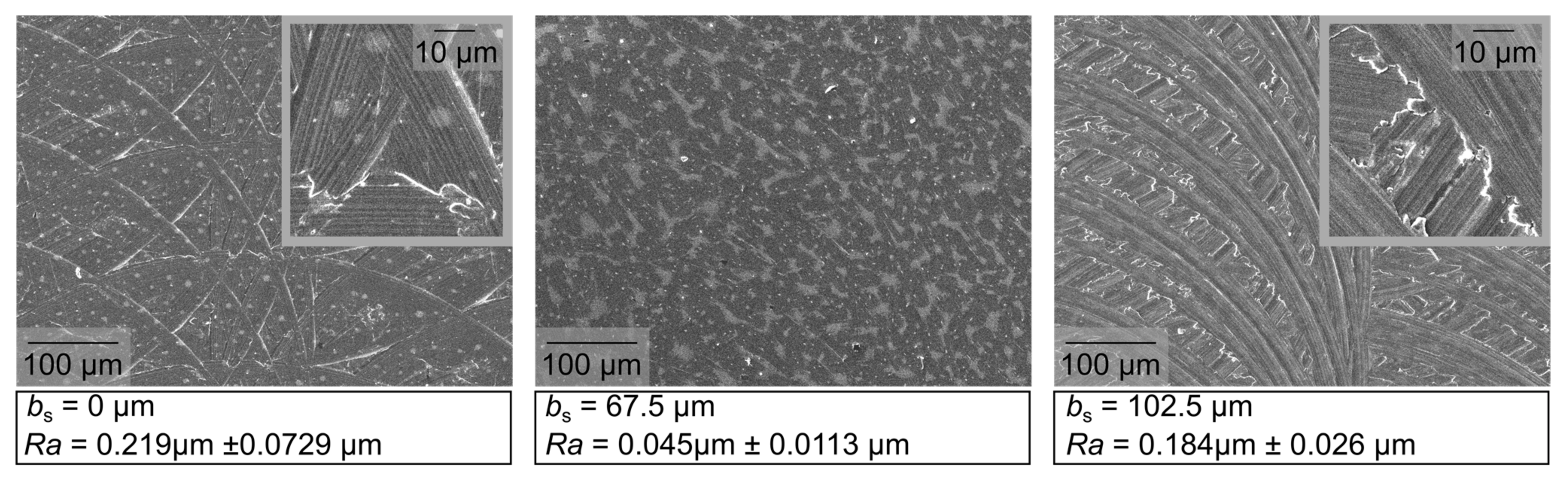
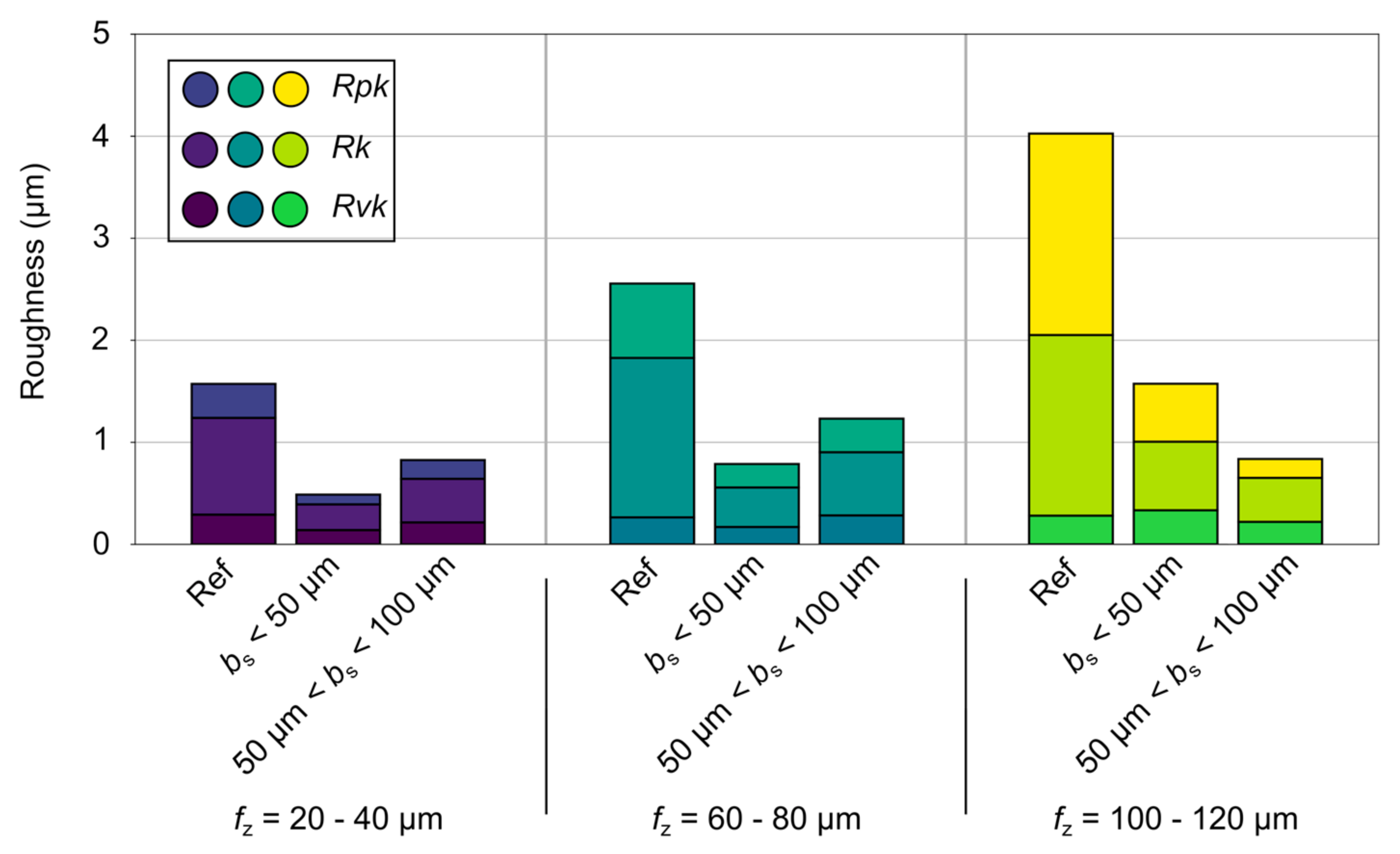
3.2.1. Surface Topography and Roughness Characteristics
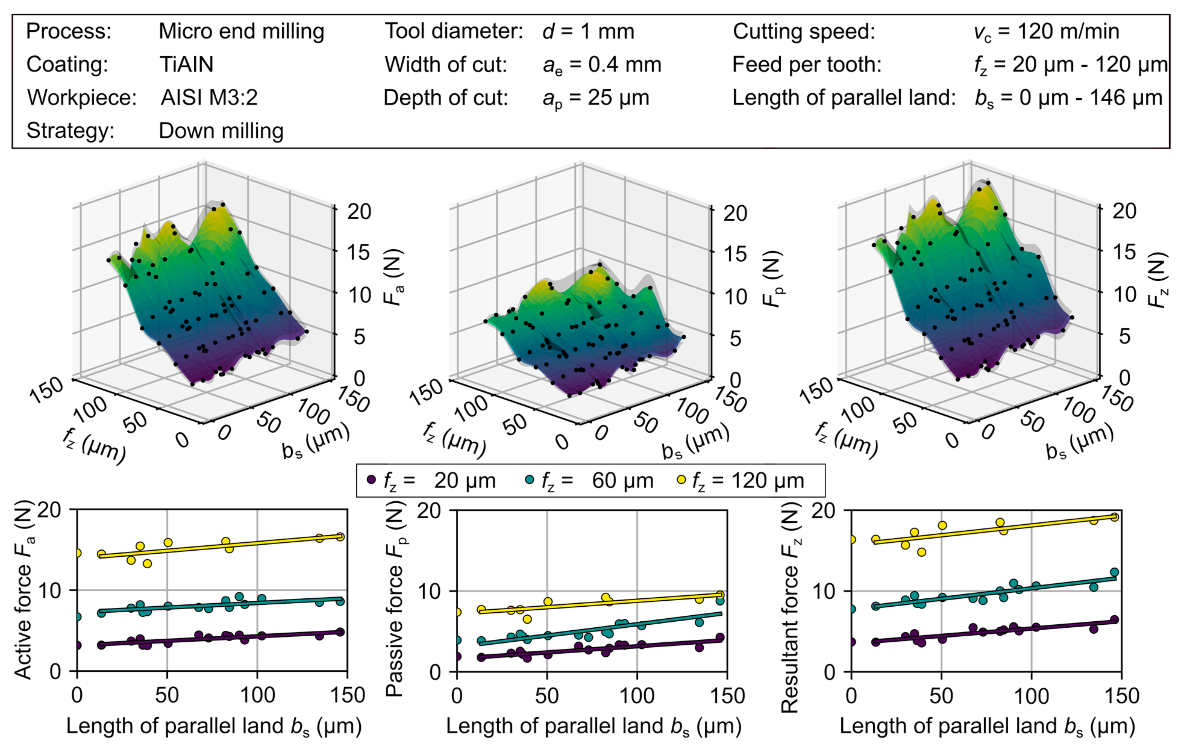
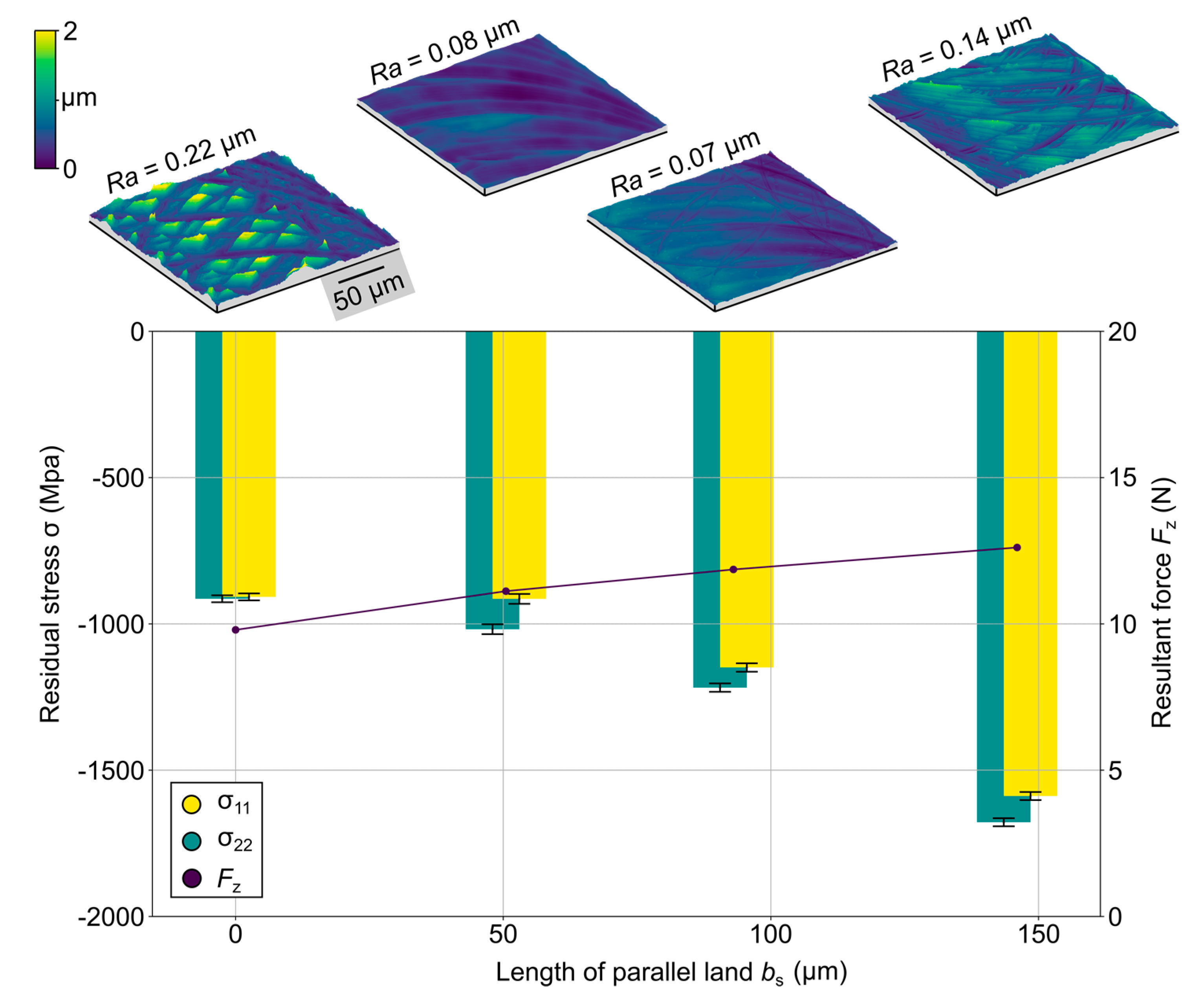
3.2.2. Cutting Force and Residual Stress State
4. Conclusions
- The simulation-assisted development of micro end mills with wiper geometries demonstrated a high potential based on the visualization of the achievable surface finish.
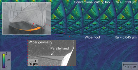
- Compared to the conventionally designed cutting tools, the wiper tools showed a significant improvement in the achievable surface topography for determined ratios of the parallel land length and the feed per tooth bs/fz. This included a reduction of the arithmetic mean roughness up to 75% (Ra = 29 nm) and 84% (Ra 59 nm) for the values of the feed per tooth fz = 20 and 120 µm with a remarkably low standard deviation.
- The measured cutting forces showed a minor impact of the modification, e.g., the length of parallel land, bs.
- Higher values for the compressive residual stress could be observed with increased wiper geometry.
- In addition, wiper geometries enable higher material removal rates and thus an increase in productivity at enhanced surface quality.
- In order to obtain essential information about relevant influencing factors, a significance analysis based on a parameter study for relevant cutting parameters, especially for the cutting speed, is of interest.
- The consideration of the tool’s lifetime and the specific wear mechanism and different materials can provide evidence of the degree of permanence of the positive effects observed.
- The demonstrated influence on the stress state shows a high potential for the topic of “surface integrity”, which could be further investigated in terms of induced stress state and micro hardness in combination with favorable surface topographies.
- Preparation of the cutting edge of tools with wiper geometry by wet abrasive jet machining to achieve a higher resistance to mechanical load.
- Occurrence or elimination of dynamic effects due to additional friction and damping caused by the increased contact surface behind the cutting edge has not yet been investigated and could be interesting for both micro and macro machining.
Author Contributions
Funding
Data Availability Statement
Conflicts of Interest
Nomenclature
| AN | Numerical aperture | Rpk | Reduced peak height |
| ae | Width of cut | Rth | Theoretical max. roughness depth |
| amax | Acceleration | Rs | Roughness of cutting edge |
| ap | Depth of cut | Rvk | Reduced valley depth |
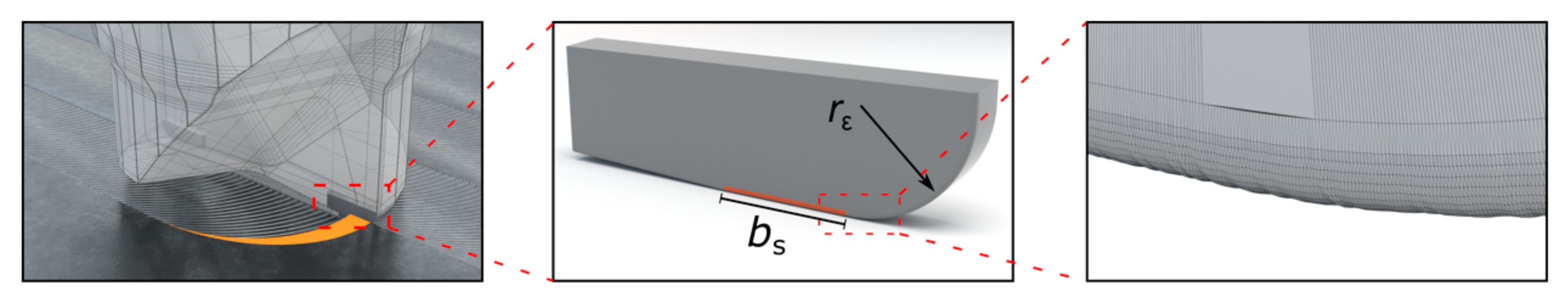
| bs | Length of parallel land | r2 | Run-out radius |
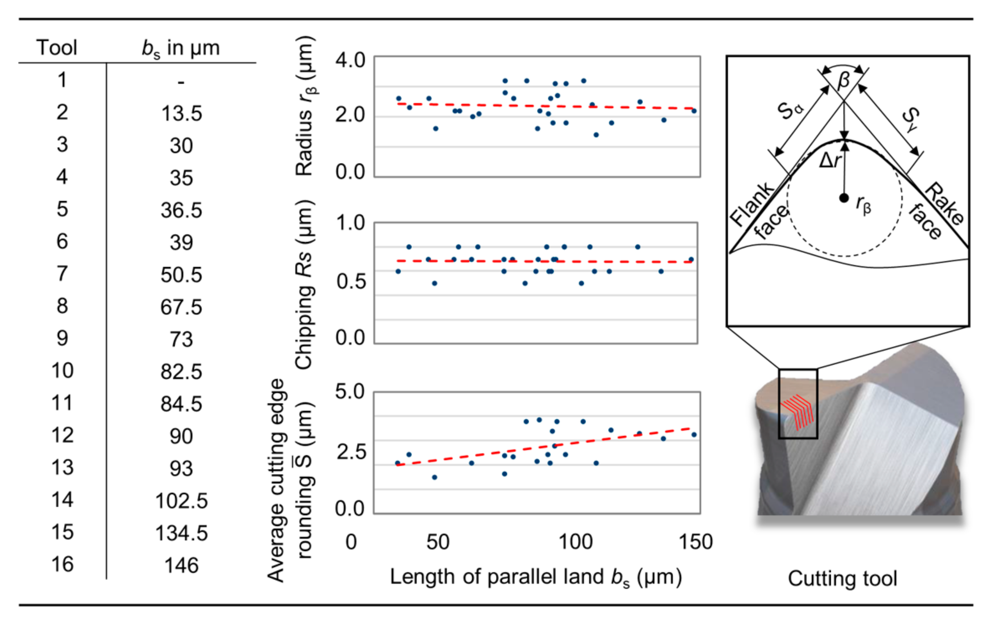
| bw | Width of parallel land | rβ | Radius |
| DoE | Design of Experiments | rε | Corner radius |
| d | Diameter | Mean cutting edge roundness | |
| dD | Lateral precision of highfield | SEM | Secondary electron microscope |
| Fa | Active force | s | Standard deviation |
| FF | Flank face | Sα | Cutting edge segment on flank face |
| Fp | Passive force | Sγ | Cutting edge segment on rake face |
| Fz | Resulting force | vc | Cutting speed |
| fn | Natural frequency | vf,max | Maximum feed rate |
| fz | Feed per tooth | zn | Cutting edges |
| HRC | Hardness Rockwell C Scale | α | Clearance angle |
| HWS | Hot work tool steel | β | Wedge angle |
| l | Tool path length | γ | Rake angle |
| MRS | Material removal simulation | Δr | Radius delta |
| n | Rotational speed range | σ | Residual stress |
| Ra | Arithmetic mean roughness | φ | Rotation angle |
| RF | Rake face | ψ | Angle of minor cutting edge |
| Rk | Core roughness depth | ψt | Tilt angle |
References
- Denkena, B.; Hoffmeister, H.-W.; Reichstein, M.; Illenseer, S.; Hlavac, M. Micro-machining processes for microsystem technology. Microsyst. Technol. 2006, 12, 659–664. [Google Scholar] [CrossRef]
- Vollertsen, F.; Biermann, D.; Hansen, H.N.; Jawahir, I.S.; Kuzman, K. Size effects in manufacturing of metallic components. CIRP Ann. Manuf. Technol. 2009, 58, 566–587. [Google Scholar] [CrossRef]
- Aramcharoen, A.; Mativenga, P.T. Size effect and tool geometry in micromilling of tool steel. Prec. Eng. 2009, 33, 402–407. [Google Scholar] [CrossRef]
- Biermann, D.; Baschin, A.; Krebs, E.; Schlenker, J. Manufacturing of dies from hardened tool steels by 3-axis micromilling. Prod. Eng. Res. Devel. 2011, 5, 209–217. [Google Scholar] [CrossRef]
- Markopoulos, A.P.; Karkalos, N.E.; Mia, M.; Pimenov, D.Y.; Gupta, M.K.; Hegab, H.; Khanna, N.; Balogun, V.A.; Sharma, S. Sustainability Assessment, Investigations, and Modelling of Slot Milling Characteristics in Eco-Benign Machining of Hardened Steel. Metals 2020, 10, 1650. [Google Scholar] [CrossRef]
- Pimenov, D.Y.; Abbas, A.T.; Gupta, M.K.; Erdakov, I.N.; Soliman, M.S.; Rayes, M.M.E. Investigations of surface quality and energy consumption associated with cost and material removal rate during face milling of AISI 1045 steel. Int. J. Adv. Manu. Tech. 2020, 107, 3511–3525. [Google Scholar] [CrossRef]
- Schaal, N. Grundlagen der Schlichtbearbeitung mit Wiper-Geometrien. Doctoral Thesis, ETH Zurich, Zürich, Switzerland, 2020. [Google Scholar]
- Toledo, J.V.R.; Arruda, E.M.; Júnior, S.C.C.; Diniz, A.E.; Ferreira, J.R. Performance of wiper geometry carbide tools in face milling of AISI 1045 steel. J. Bra. Soc. Mech. Scie. Eng. 2018, 40, 478. [Google Scholar] [CrossRef]
- Jones, F. Turning and Boring; The Industrial Press: New York, NY, USA, 1914. [Google Scholar]
- Rose, J. Modern Machine-Shop Practice; Charles Scribner’s Sons: New York, NY, USA, 1901. [Google Scholar]
- Grzesik, W.; Wanat, T. Surface roughness measurement in turning carbon steel AISI 1045 using wiper inserts. Measurement 2006, 44, 1000–1005. [Google Scholar]
- DIN 8589-1. Fertigungsverfahren Spanen—Teil 1: Drehen; Einordnung, Unterteilung, Begriffe; Beuth: Berlin, Germany, 2003. [Google Scholar]
- Kurniawan, D.; Mohd, N.; Sharif, Y.; Sharif, S. Hard Machining of Stainless Steel Using Wiper Coated Carbide: Tool Life and Surface Integrity. Mater. Manuf. Process. 2010, 25, 370–377. [Google Scholar] [CrossRef]
- D’Addona, A.M.; Raykar, S.J. Analysis of surface roughness in hard turning using wiper insert geometry. Procedia CIRP CMS 2015, 41, 841–846. [Google Scholar] [CrossRef]
- De Souza, A.M., Jr.; Sales, W.F.; Santos, S.C.; Machado, A.R. Performance of single Si3N4 and mixed Si3N4+PCBN wiper cutting tools applied to high speed face milling of cast iron. Int. J. Mach. Tools Manuf. 2004, 45, 335–344. [Google Scholar] [CrossRef]
- Saleem, Q.S.; Mumtaz, S. Face milling of Inconel 625 via wiper inserts: Evaluation of tool life and workpiece integrity. J. Manuf. Pro. 2020, 56, 322–336. [Google Scholar] [CrossRef]
- Ehsan, S.; Khan, S.A.; Mughal, M.P.; Saleem, M.Q.; Mufti, N.A. Milling of Ti-6Al-4V alloy using hybrid geometry tooling. Int. J. Adv. Manuf. Technol. 2019, 105, 5045–5059. [Google Scholar] [CrossRef]
- Ehsan, S.; Khan, S.A.; Rehman, M. Defect-free high-feed milling of Ti-6Al-4V alloy via a combination of cutting and wiper inserts. Int. J. Adv. Manuf. Technol. 2021. [Google Scholar] [CrossRef]
- Benardos, P.G.; Vosniakos, G.-C. Predicting surface roughness in machining: A review. Int. J. Mach. Tools Manuf. 2003, 43, 833–844. [Google Scholar] [CrossRef]
- Meijer, A.; Bergmann, J.A.; Krebs, E.; Biermann, D. Analytical and Simulation-Based Prediction of Surface Roughness for Micromilling Hardened HSS. J. Manuf. Mater. Process. 2019, 3, 1–17. [Google Scholar] [CrossRef] [Green Version]
- Bauer, M.H. Messen der Oberflächengüte. Masch. Der Betr. 1934, 13, 81–83. [Google Scholar]
- Shaw, M.C.; Cookson, J.O. Geometrical contribution to roughness. Met. Cut. Princ. 2005, 449–452. [Google Scholar]
- Martellotti, M.E. An analysis of the milling process. Trans. ASME 1941, 63, 677–700. [Google Scholar]
- Biermann, D.; Meijer, A.; Bücker, M.; Aßmuth, R.; Tiffe, M.; Fuß, M.; Metzger, M. Pulvermetallurgie der Hartmetalle—Schlüsseltechnologie für die spanende Fertigung und ihre Anwendungsgebiete. In Pulvermetallurgie—Schlüsseltechnologie für Innovative Systemlösungen; Heimdall Verlag: Dortmund, Germany, 2019; Volume 35, pp. 3–27. ISBN 978-3-946537-65-6. [Google Scholar]
- Denkena, B.; Reichstein, M.; Brofehl, J.; Garcia Lde, L. Surface Preparation, Coating and Wear Performance of Geometrically Defined Cutting Edges. In Proceedings of the 8th CIRP International Workshop on Modeling of Machining Operations, Chemnitz, Germany, 10–11 May 2005. [Google Scholar]
- Noyan, I.C.; Cohen, J.B. Residual Stress: Measurement by Diffraction and Interpretation; Springer: New York, NY, USA, 1987. [Google Scholar]


| Properties | Value |
|---|---|
| Tool diameter | d = 1 mm |
| Corner radius | rε = 50 µm |
| Cutting edges | zn = 2 |
| Rake angle | γ = 0° |
| Clearance angle | α = 10° |
| Mean cutting edge roundness | = 2.3 μm |
| Roughness of cutting edge | Rs = 0.7 µm |
| Parallel land | bs = 0, 10, 35, 60, 95, 110 µm |
| C | Si | Mn | Cr | Mo | V |
|---|---|---|---|---|---|
| 0.38 | 1.00 | 0.40 | 5.30 | 1.20 | 0.40 |
| Length of Parallel Land (bs) | Feed per Tooth (fz) | Cutting Speed (vc) |
|---|---|---|
| 13.5–146 µm | 20–80 µm | 120 m/min |
| 100–120 µm | 75 1 m/min |
| Ra (nm) | ||||||
|---|---|---|---|---|---|---|
| bs in µm | fz = 20 µm | fz = 40 µm | fz = 60 µm | fz = 80 µm | fz = 100 µm | fz = 120 µm |
| Reference | 117 ± 37 | 239 ± 98 | 219 ± 73 | 335 ± 129 | 324 ± 139 | 375 ± 173 |
| 13.5 | 43 ± 11 | 71 ± 19 | 93 ± 19 | 114 ± 50 | 174 ± 57 | 189 ± 55 |
| 30.0 | 29 ± 11 | 49 ± 17 | 59 ± 16 | 70 ± 23 | 135 ± 48 | 146 ± 76 |
| 35.0 | 32 ± 5 | 50 ± 12 | 77 ± 32 | 41 ± 17 | 118 ± 19 | 123 ± 48 |
| 36.5 | 31 ± 3 | 45 ± 12 | 64 ± 17 | 75 ± 22 | 116 ± 64 | 195 ± 96 |
| 39.0 | 45 ± 13 | 33 ± 5 | 47 ± 10 | 75 ± 15 | 101 ± 24 | 180 ± 110 |
| 50.5 | 52 ± 6 | 43 ± 8 | 60 ± 19 | 86 ± 26 | 80 ± 28 | 87 ± 19 |
| 67.5 | 29 ± 6 | 39 ± 5 | 45 ± 11 | 57 ± 9 | 63 ± 18 | 64 ± 15 |
| 73.0 | 125 ± 33 | 55 ± 12 | 54 ± 11 | 111 ± 19 | 76 ± 16 | 71 ± 11 |
| 82.5 | 52 ± 6 | 41 ± 7 | 57 ± 13 | 65 ± 17 | 78 ± 22 | 86 ± 17 |
| 84.5 | 206 ± 68 | 29 ± 6 | 168 ± 42 | 60 ± 11 | 90 ± 24 | 82 ± 22 |
| 90.0 | 29 ± 5 | 40 ± 3 | 259 ± 53 | 310 ± 62 | 99 ± 20 | 84 ± 24 |
| 93.0 | 36 ± 6 | 40 ± 9 | 56 ± 15 | 40 ± 7 | 67 ± 18 | 69 ± 12 |
| 102.5 | 158 ± 23 | 166 ± 41 | 184 ± 26 | 153 ± 29 | 51 ± 13 | 59 ± 16 |
| 134.5 | 235 ± 22 | 169 ± 30 | 202 ± 61 | 196 ± 56 | 96 ± 17 | 279 ± 79 |
| 146.0 | 262 ± 71 | 184 ± 44 | 205 ± 52 | 241 ± 67 | 192 ± 58 | 227 ± 42 |
Publisher’s Note: MDPI stays neutral with regard to jurisdictional claims in published maps and institutional affiliations. |
© 2021 by the authors. Licensee MDPI, Basel, Switzerland. This article is an open access article distributed under the terms and conditions of the Creative Commons Attribution (CC BY) license (https://creativecommons.org/licenses/by/4.0/).
Share and Cite
Platt, T.; Meijer, A.; Merhofe, T.; Biermann, D. Simulation-Based and Experimental Investigation of Micro End Mills with Wiper Geometry. Micromachines 2021, 12, 496. https://doi.org/10.3390/mi12050496
Platt T, Meijer A, Merhofe T, Biermann D. Simulation-Based and Experimental Investigation of Micro End Mills with Wiper Geometry. Micromachines. 2021; 12(5):496. https://doi.org/10.3390/mi12050496
Chicago/Turabian StylePlatt, Timo, Alexander Meijer, Torben Merhofe, and Dirk Biermann. 2021. "Simulation-Based and Experimental Investigation of Micro End Mills with Wiper Geometry" Micromachines 12, no. 5: 496. https://doi.org/10.3390/mi12050496