
An Investigation of the High-Frequency Ultrasonic Vibration-Assisted Cutting of Steel Optical Moulds


Abstract
:1. Introduction
2. Working Principle and Cutting Mechanics Of UVAC
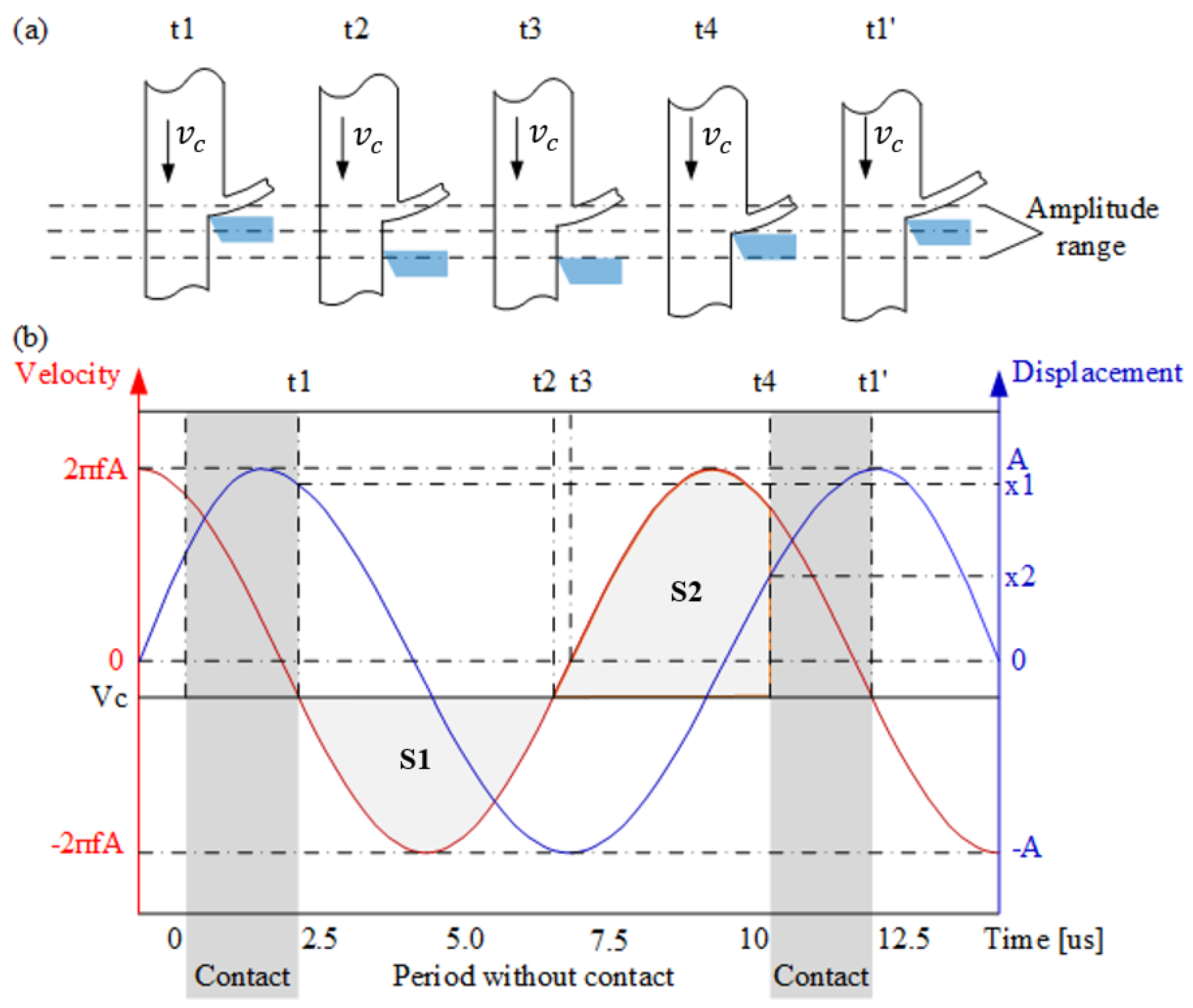
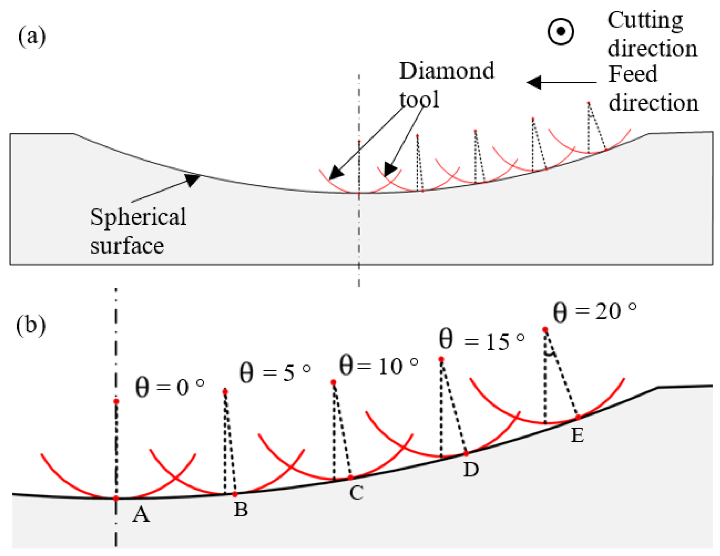
2.1. Cutting Mechanics
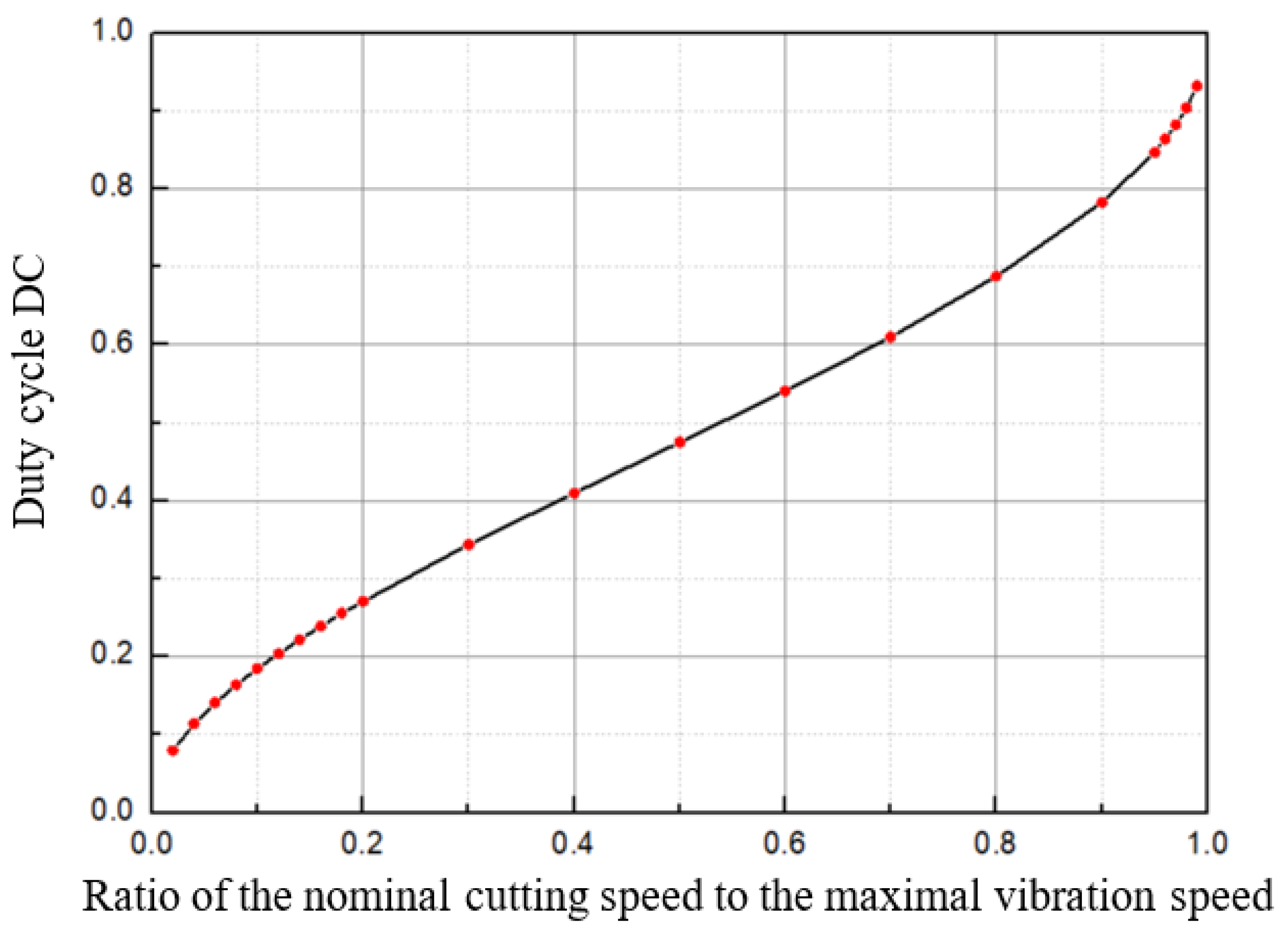
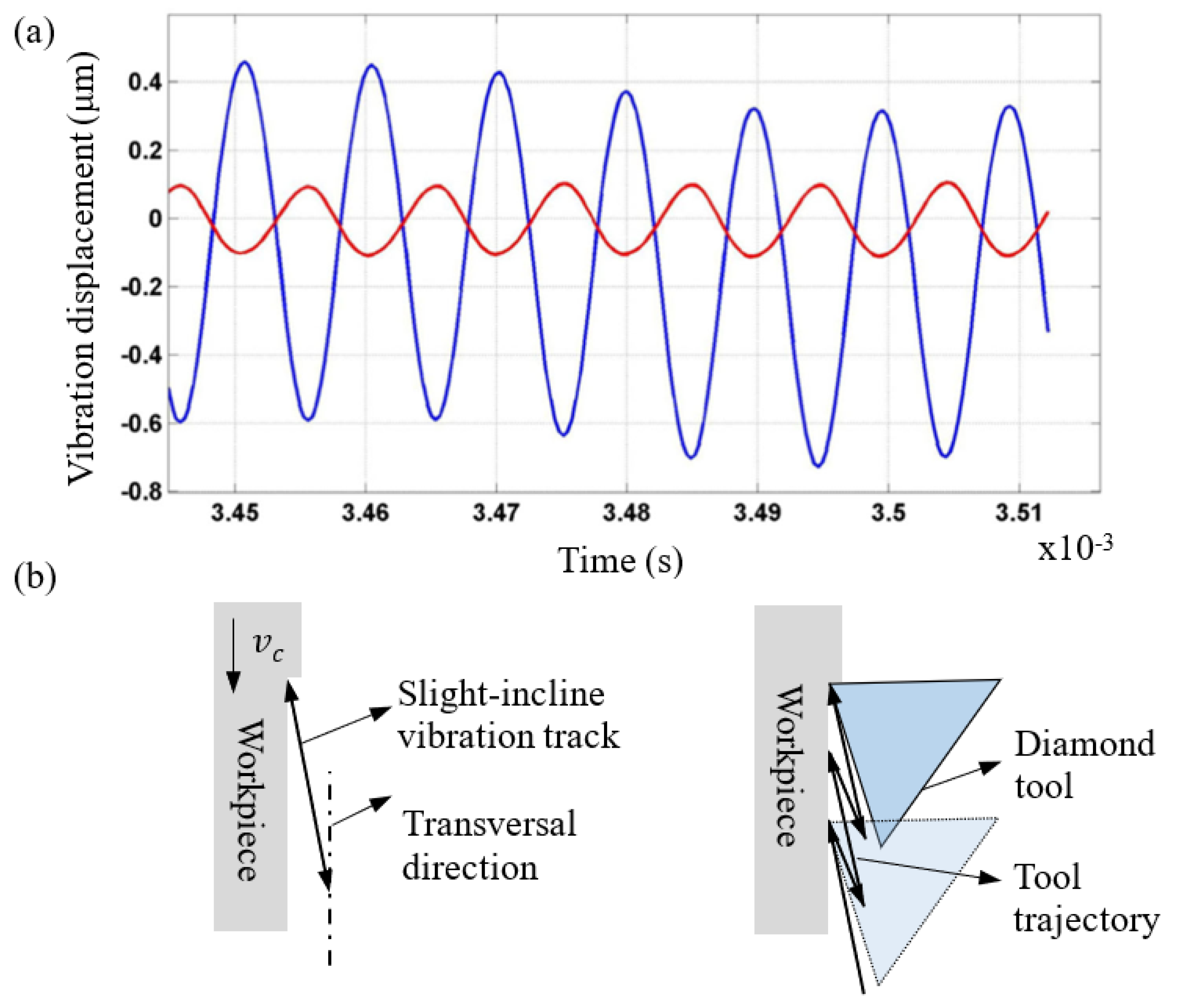
2.2. The Applied High-Frequency UVAC
3. Experiment
3.1. Machining Dimension and Material of the Moulds
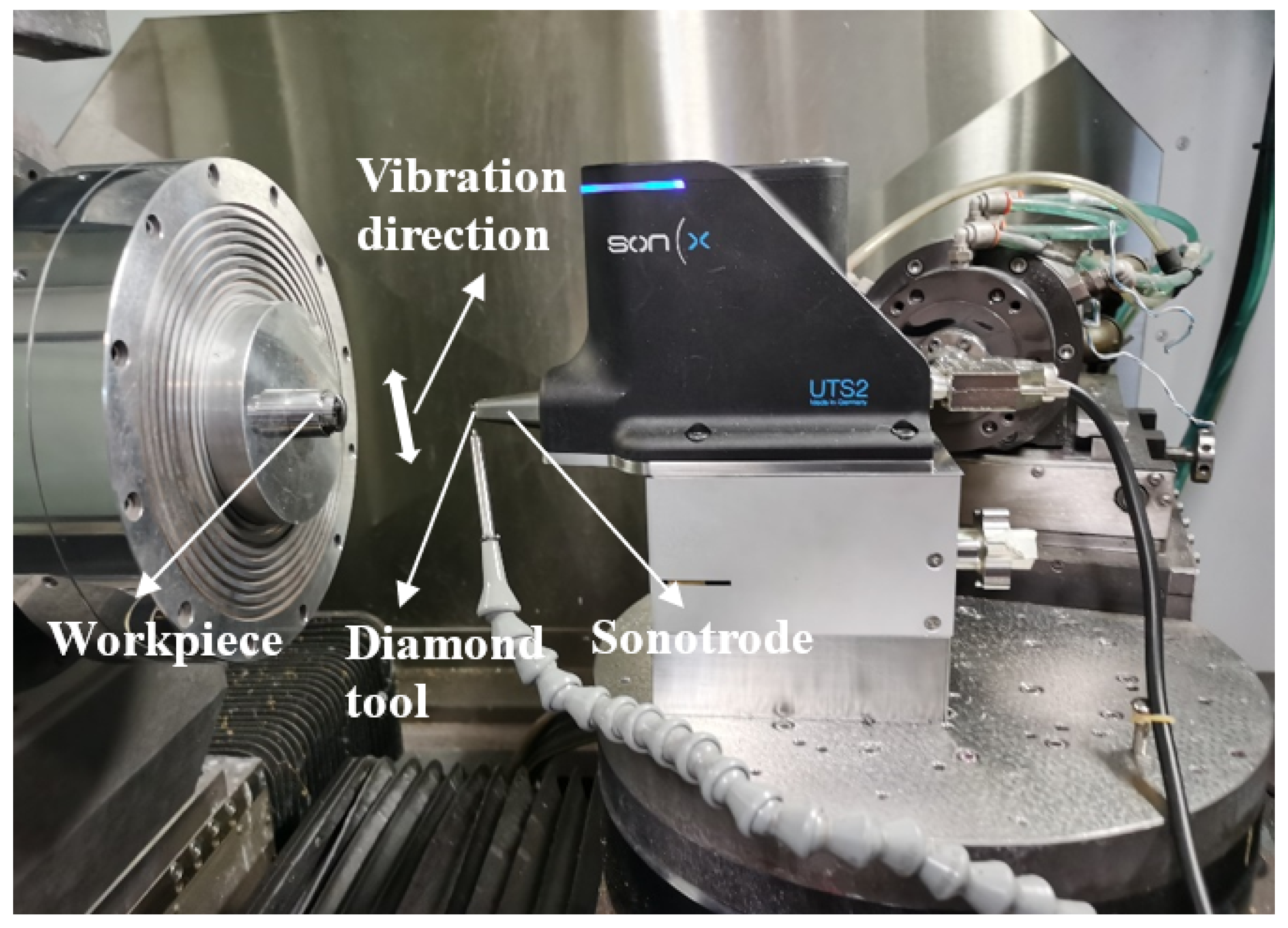
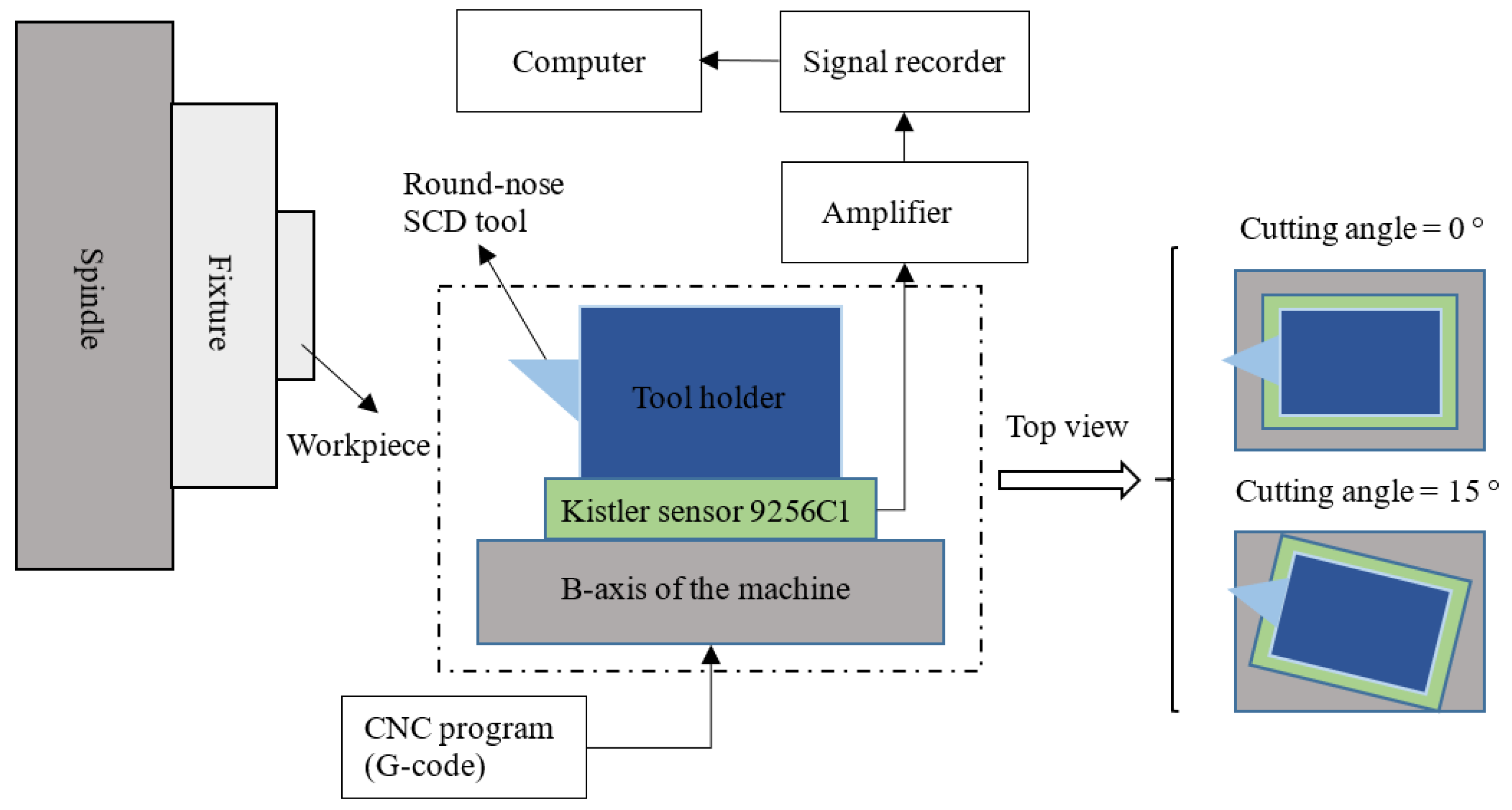
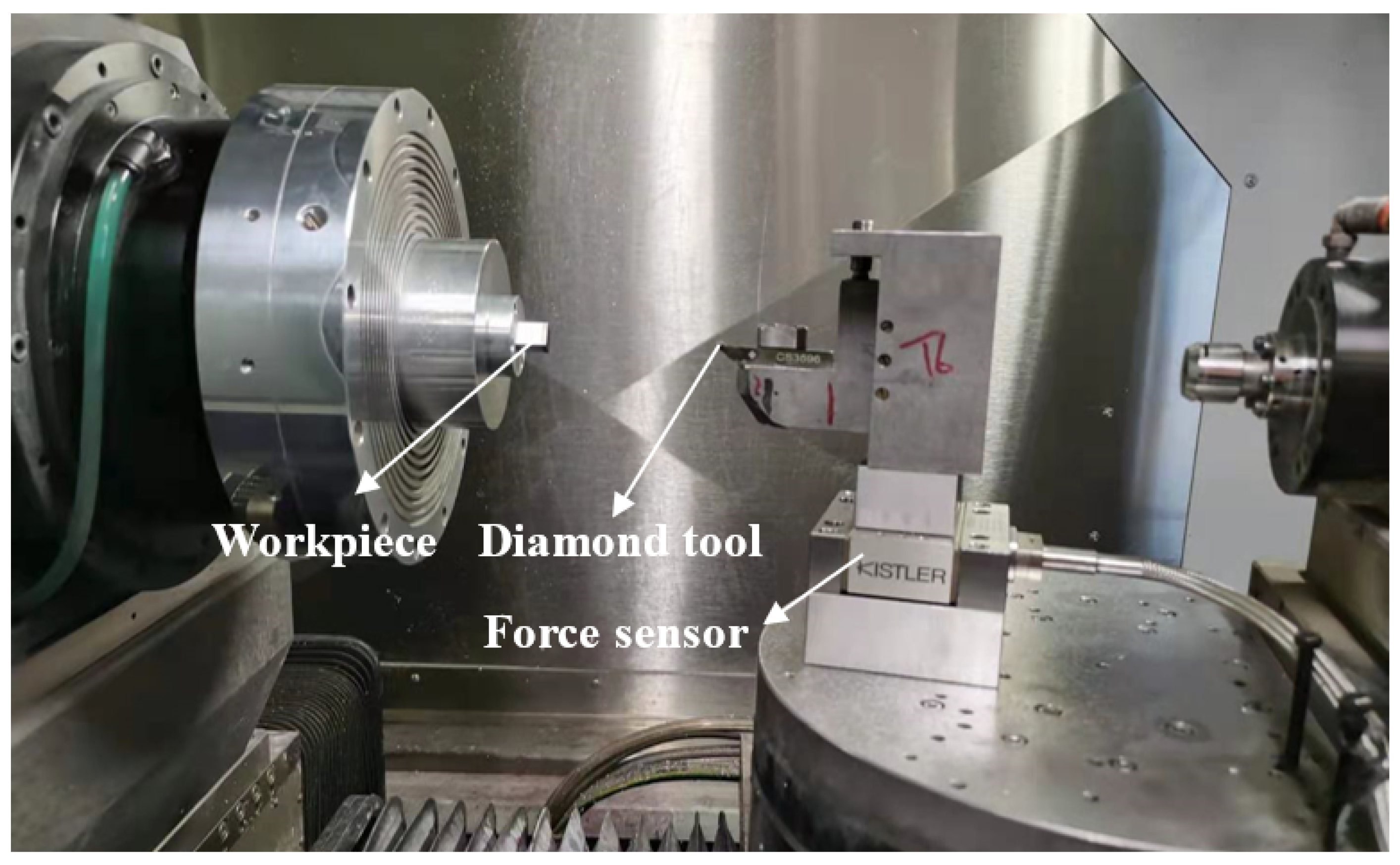
3.2. Procedures and Setup
3.3. Experimental Design Using the Taguchi Method
3.4. Data Analysis for the Taguchi Method
4. Results and Discussions
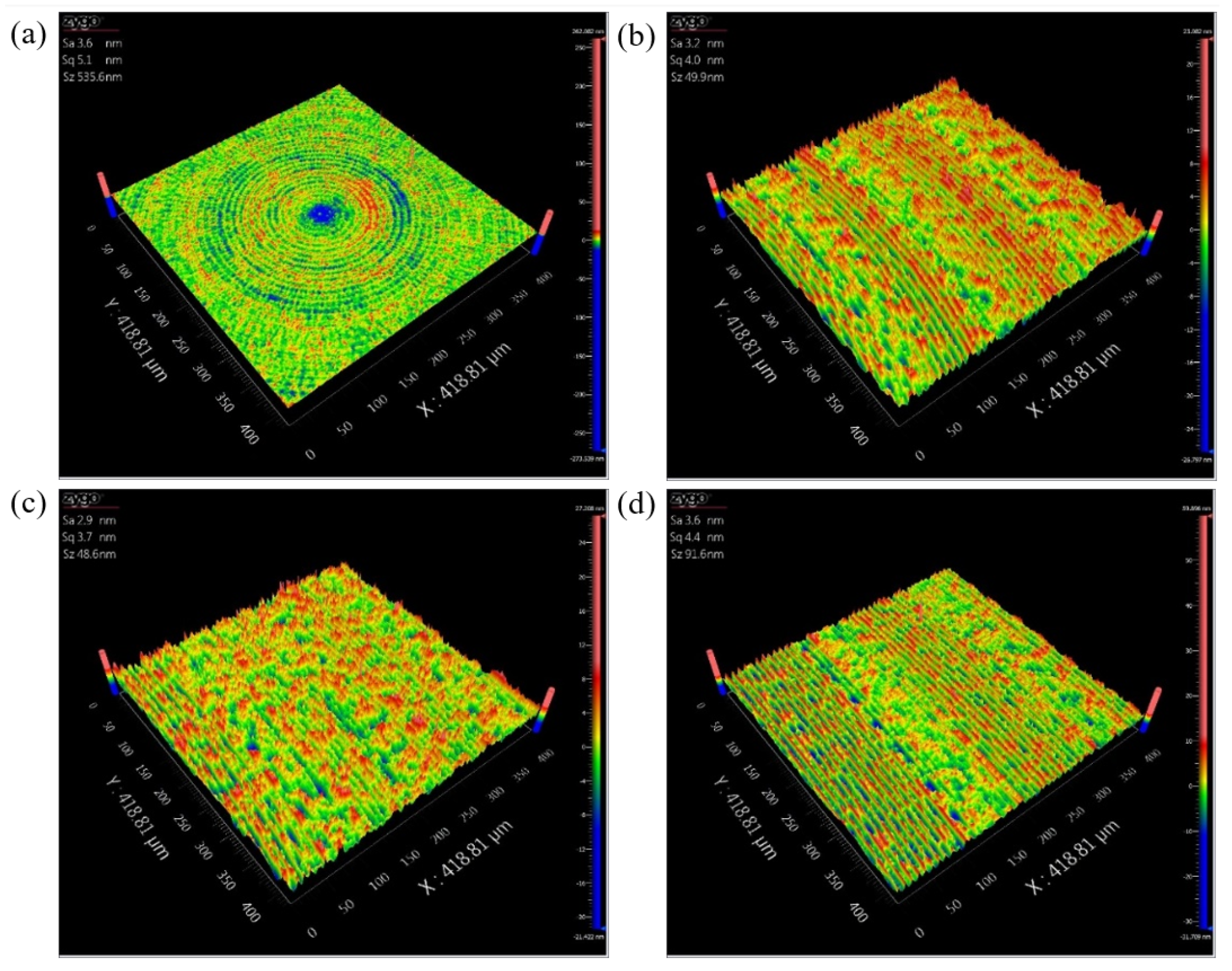
4.1. Surface Roughness Analysis
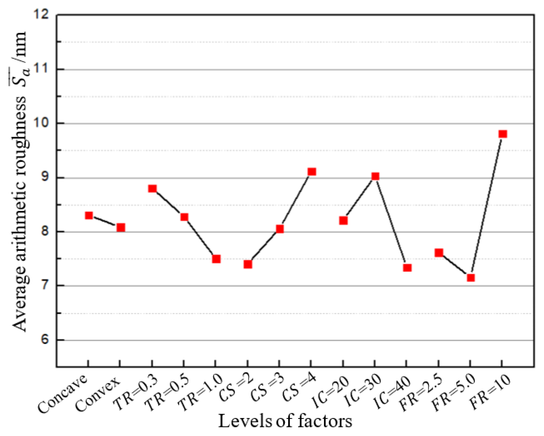
4.1.1. Average Arithmetic Roughness for Various Levels of Each Factor
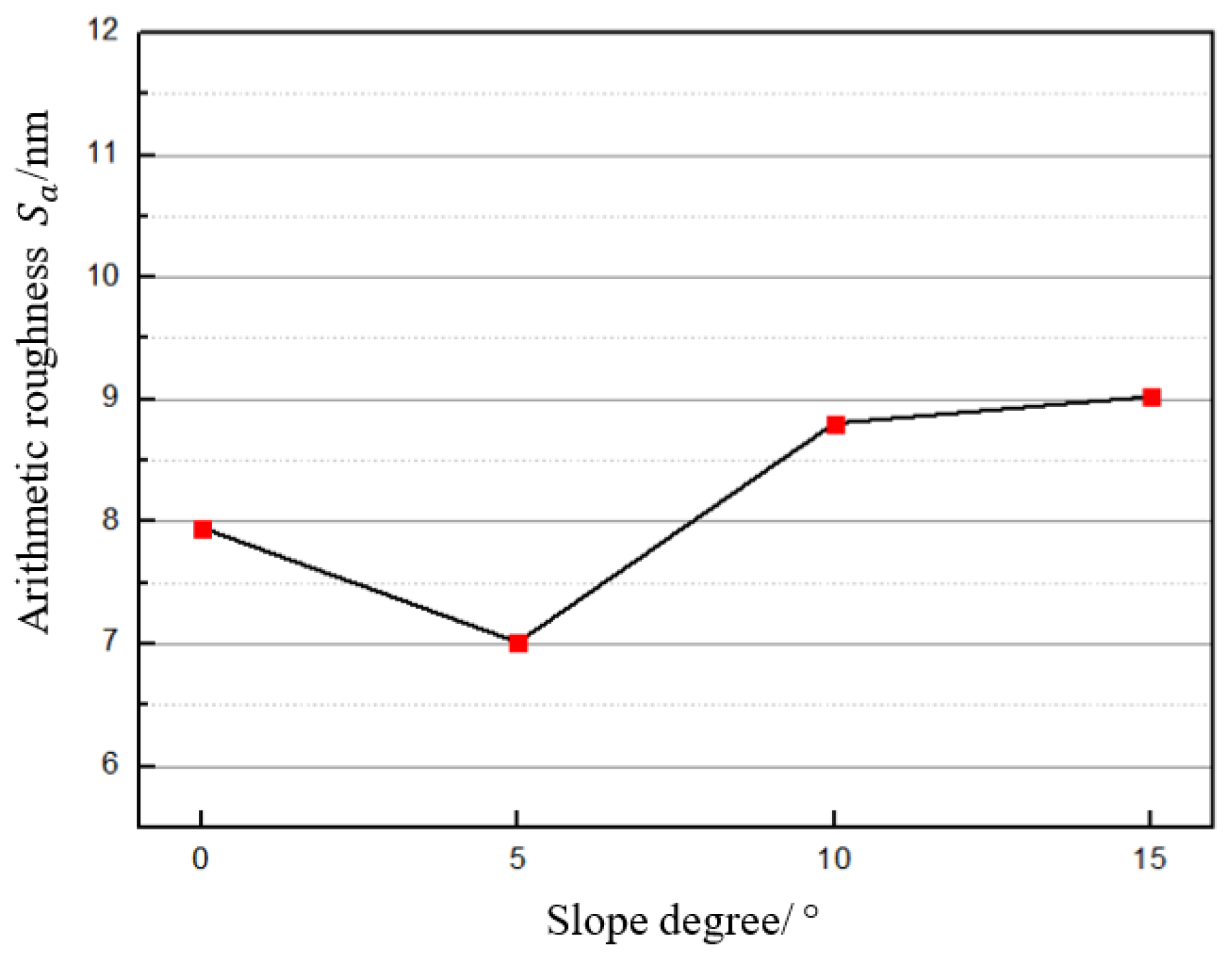
4.1.2. Arithmetic Roughness for Each SD
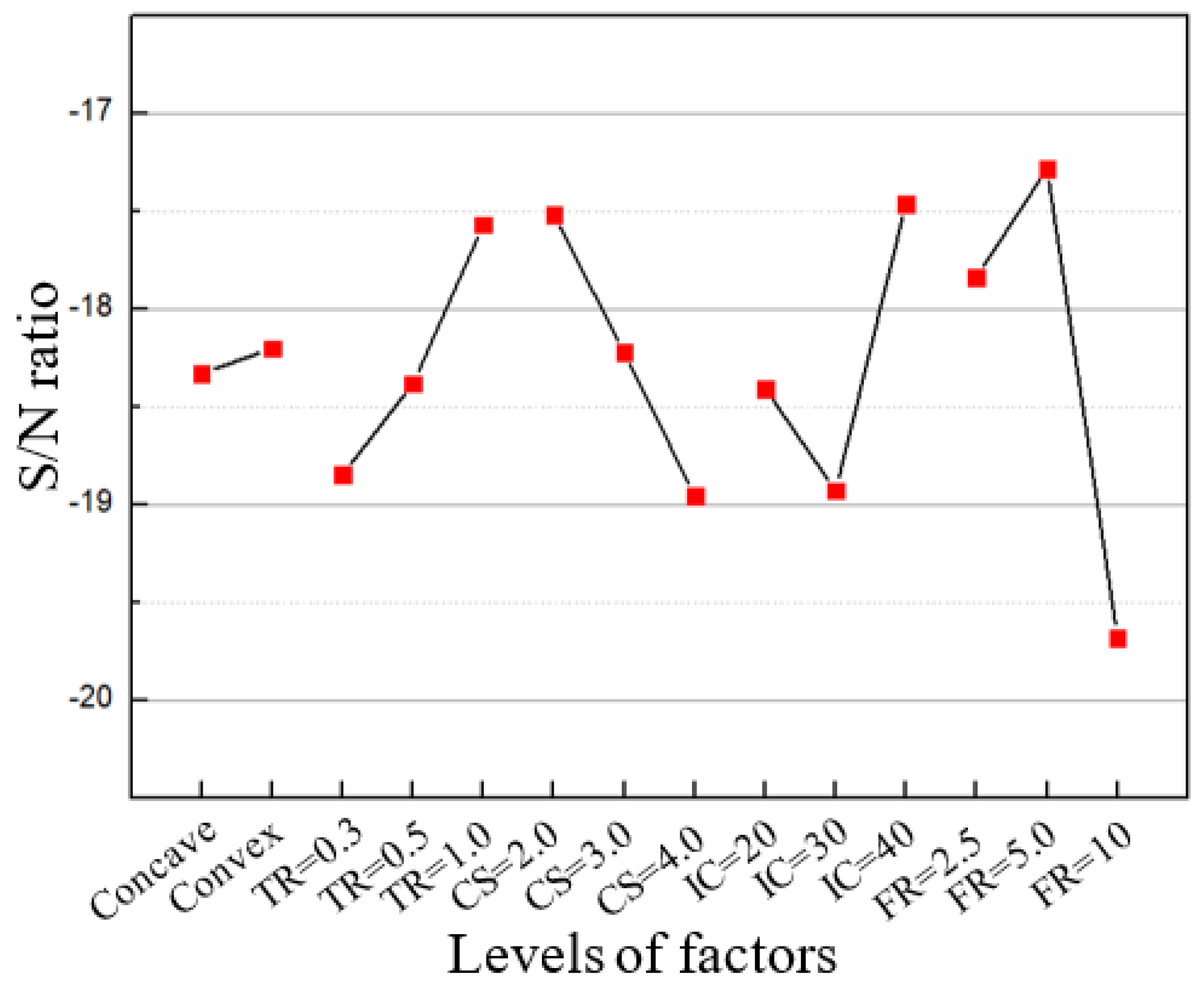
4.2. Optimisation of the Level for Each Factor
5. Conclusions
- Feed rate has the greatest effect on the surface roughness of the workpiece: 5 μm/res was able to achieve better surface roughness compared with 10 μm/res and 2.5 μm/res. Under the selected levels of the other factors, surface roughness decreased with increasing tool radius while it increased with increasing nominal cutting speed. The effect of input current on surface roughness remains unclear based on the obtained results.
- To achieve a better surface finish, the optimal combination of the level for each cutting parameter is 1 mm for tool radius, 2 m/min for cutting speed, 20 mA for input current, and 5 m per rev for feed rate.
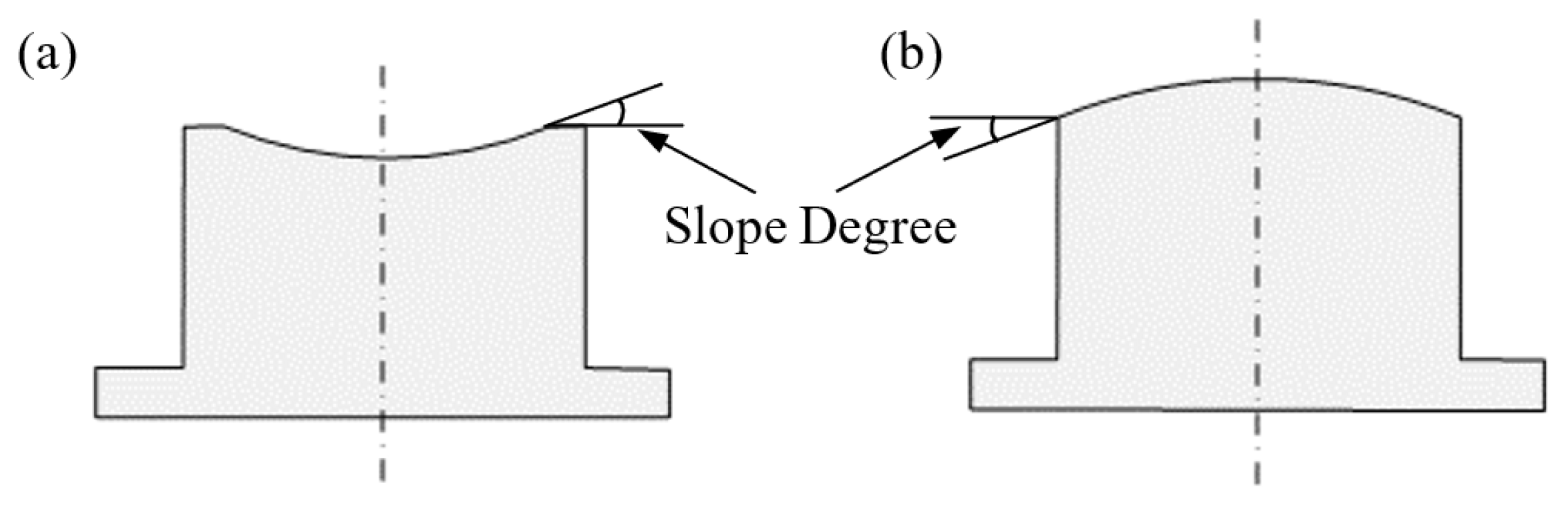
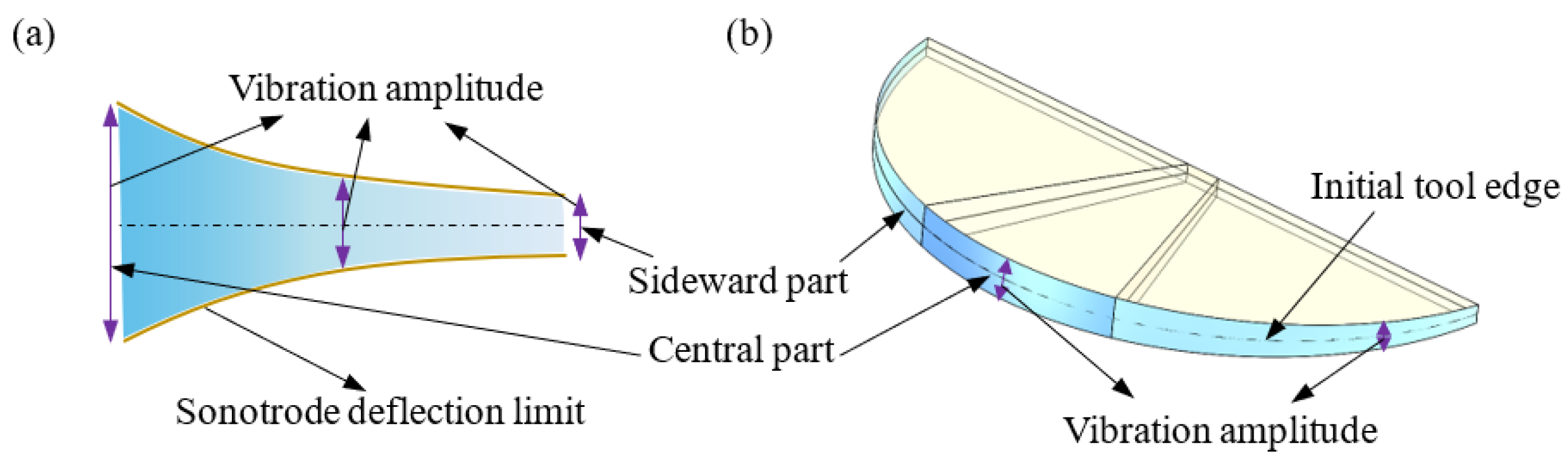
- Arithmetic roughness on the machined spherical steel mould exhibited a slight upward trend with an increase in slope degree from 5° to 15°, and the variation in vibration amplitude distribution along the tool edge arising in the bending vibration mode is speculated to be the possible reason.
- Under optimal cutting conditions, the optical surface quality, with an arithmetic roughness of 3–4 nm, can be achieved at various slope Degrees. Furthermore, the unevenness of surface finishes at various slope degrees was alleviated in this ultrasonic tooling system with a combination of optimal parameters.
Author Contributions
Funding
Acknowledgments
Conflicts of Interest
Nomenclature
| UVAC | Ultrasonic vibration-assisted cutting |
| SD | Slope degree |
| Arithmetic surface roughness | |
| Average arithmetic surface roughness | |
| CBN | Cubic boron nitride |
| SPDT | Single point diamond turning |
| CUAC or 1D UVC | Conventional ultrasonic vibration cutting |
| UEVC | Ultrasonic elliptical vibration cutting |
| PCD | Poly-crystalline diamond |
| f | Vibration frequency |
| A | Vibration amplitude |
| Nominal cutting speed | |
| DC | Duty cycle |
| TR | Tool radius |
| CS | Cutting speed, namely nominal cutting speed |
| IC | Input current |
| FR | Feed rate |
| Signal-to-noise ratio | |
| CSS | Constant surface speed |
References
- Vopát, T.; Sahul, M.; Haršáni, M.; Vortel, O.; Zlámal, T. The tool life and coating-substrate adhesion of AlCrSiN-coated carbide cutting tools prepared by LARC with respect to the edge preparation and surface finishing. Micromachines 2020, 11, 166. [Google Scholar] [CrossRef] [Green Version]
- Kuntoğlu, M.; Aslan, A.; Pimenov, D.Y.; Giasin, K.; Mikolajczyk, T.; Sharma, S. Modeling of cutting parameters and tool geometry for multi-criteria optimization of surface roughness and vibration via response surface methodology in turning of AISI 5140 steel. Materials 2020, 13, 4242. [Google Scholar] [CrossRef]
- Kumar, P.; Chauhan, S.R.; Pruncu, C.I.; Gupta, M.K.; Pimenov, D.Y.; Mia, M.; Gill, H.S. Influence of different grades of CBN inserts on cutting force and surface roughness of AISI H13 die tool steel during hard turning operation. Materials 2019, 12, 177. [Google Scholar] [CrossRef] [PubMed] [Green Version]
- Ikawa, N.; Donaldson, R.R.; Komanduri, R.; König, W.; Aachen, T.H.; McKeown, P.A.; Moriwaki, T.; Stowers, I.F. Ultraprecision metal cutting—The Past, the Present and the Future. CIRP Ann. Manuf. Technol. 1991, 40, 587–594. [Google Scholar] [CrossRef]
- Paul, E.; Evans, C.J.; Mangamelli, A.; McGlauflin, M.L.; Polvani, R.S. Chemical aspects of tool wear in single point diamond turning. Precis. Eng. 1996, 18, 4–19. [Google Scholar] [CrossRef]
- Guo, J.; Zhang, J.; Pan, Y.; Kang, R.; Namba, Y.; Shore, P.; Yue, X.; Wang, B.; Guo, D. A critical review on the chemical wear and wear suppression of diamond tools in diamond cutting of ferrous metals. Int. J. Extrem. Manuf. 2020, 2, 12001. [Google Scholar]
- Evans, C.; Bryan, J.B. Cryogenic diamond turning of stainless steel. CIRP Ann. Manuf. Technol. 1991, 40, 571–575. [Google Scholar] [CrossRef]
- Casstevens, J. Diamond turning of steel in carbon-saturated Diamond turning of steel in carbon-saturated atmospheres. Precis. Eng. 1983, 5, 9–15. [Google Scholar] [CrossRef]
- Moriwaki, T.; Shamoto, E. Ultraprecision diamond turning of stainless steel by applying ultrasonic vibration. CIRP Ann. Manuf. Technol. 1991, 40, 559–562. [Google Scholar] [CrossRef]
- Coelho, R.T.; Ng, E.-G.; Elbestawi, M.A. Tool wear when turning hardened AISI 4340 with coated PCBN tools using finishing cutting conditions. Int. J. Mach. Tools Manuf. 2007, 47, 263–272. [Google Scholar] [CrossRef]
- Aslan, E.; Camuşcu, N.; Birgören, B. Design optimization of cutting parameters when turning hardened AISI 4140 steel (63 HRC) with Al2O3+TiCN mixed ceramic tool. Mater. Des. 2007, 28, 1618–1622. [Google Scholar] [CrossRef]
- Shamoto, E.; Moriwaki, T. Study on Elliptical Vibration Cutting. CIRP Ann-Manuf. Technol. 1994, 43, 35–38. [Google Scholar] [CrossRef]
- Shamoto, E.; Moriwaki, T. Ultaprecision diamond cutting of hardened steel by applying elliptical vibration cutting. CIRP Ann. Manuf. Technol. 1999, 48, 441–444. [Google Scholar] [CrossRef]
- Li, L.; Yang, G.; Lee, W.B.; Ng, M.C.; Chan, K.L. Carbide-bonded graphene-based Joule heating for embossing fine microstructures on optical glass. Appl. Surf. Sci. 2020, 500, 144004. [Google Scholar] [CrossRef]
- Mukaida, M.; Yan, J. Ductile machining of single-crystal silicon for microlens arrays by ultraprecision diamond turning using a slow tool servo. Int. J. Mach. Tools Manuf. 2017, 115, 2–14. [Google Scholar] [CrossRef]
- Zhang, X.; Senthil Kumar, A.; Rahman, M.; Nath, C.; Liu, K. Experimental study on ultrasonic elliptical vibration cutting of hardened steel using PCD tools. J. Mater. Process. Technol. 2011, 211, 1701–1709. [Google Scholar] [CrossRef]
- Klocke, F.; Dambon, O.; Bulla, B.; Heselhaus, M. Ultrasonic assisted turning of hardened steel with mono-crystalline ultrasonic assisted turning of hardened steel with mono-crystalline diamond. In Proceedings of the 10th International Euspen Conference, Zürich, Switzerland, 18–22 May 2008; pp. 165–169. [Google Scholar]
- Klocke, F.; Dambon, O.; Bulla, B. Tooling system for diamond turning of hardened steel moulds with apsheric or non rotational symmetrical geometries. In Proceedings of the 11th EUSPEN International Conference, Como, Italy, 23–26 May 2011. [Google Scholar]
- Gaidys, R.; Dambon, O.; Ostasevicius, V.; Dicke, C.; Narijauskaite, B. Ultrasonic tooling system design and development for single point diamond turning (SPDT) of ferrous metals. Int. J. Adv. Manuf. Technol. 2017, 93, 2841–2854. [Google Scholar] [CrossRef]
- Brehl, D.E.; Dow, T.A. Review of vibration-assisted machining. Precis. Eng. 2008, 32, 153–172. [Google Scholar] [CrossRef]
- Moriwaki, T.; Shamoto, E.; Inoue, K. Ultraprecision ductile cutting of glass by applying ultrasonic vibration. CIRP Ann-Manuf. Technol. 1992, 41, 141–144. [Google Scholar] [CrossRef]
- Zhang, X.; Deng, H.; Liu, K. Oxygen-shielded ultrasonic vibration cutting to suppress the chemical wear of diamond tools. CIRP Ann. Manuf. Technol. 2019, 68, 69–72. [Google Scholar] [CrossRef]
- Zhang, X.; Liu, K.; Kumar, A.S.; Rahman, M. A study of the diamond tool wear suppression mechanism in vibration-assisted machining of steel. J. Mater. Process. Technol. 2014, 214, 496–506. [Google Scholar] [CrossRef]
- Shiou, F.J.; Cheng, C.H. Ultra-precision surface finish of NAK80 mould tool steel using sequential ball burnishing and ball polishing processes. J. Mater. Process. Technol. 2008, 201, 554–559. [Google Scholar] [CrossRef]
- Nath, C.; Rahman, M.; Neo, K.S. A study on the effect of tool nose radius in ultrasonic elliptical vibration cutting of tungsten carbide. J. Mater. Process. Technol. 2009, 209, 5830–5836. [Google Scholar] [CrossRef]
- Xiao, M.; Karube, S.; Soutome, T.; Sato, K. Analysis of chatter suppression in vibration cutting. Int. J. Mach. Tools Manuf. 2002, 42, 1677–1685. [Google Scholar] [CrossRef]
- Arefin, S.; Zhang, X.; Anantharajan, S.K.; Liu, K.; Neo, D.W.K. An Analytical Model for Determining the Shear Angle in 1D Vibration-Assisted Micro Machining. Nanomanuf. Metrol. 2019, 2, 199–214. [Google Scholar] [CrossRef]
- Arcona, C.; Dow, T.A. An empirical tool force model for precision machining. J. Manuf. Sci. Eng. Trans. ASME 1998, 120, 700–707. [Google Scholar] [CrossRef]


| Factor | Level 1 | Level 2 | Level 3 |
|---|---|---|---|
| A. Tool Radius TR (mm) | 0.3 | 0.5 | 1.0 |
| B. Cutting Speed CS (m/min) | 2 | 3 | 4 |
| C. Input Current IC (mA) | 20 | 30 | 40 |
| D. Feed Rate FR (m/rev) | 2.5 | 5 | 10 |
| E. Surface form | Concave | Convex |
| Test No. | TR | CS | IC | FR | Surface Form | (nm) SD = 0° | (nm) SD = 5° | (nm) SD = 10° | (nm) SD = 15° | S/N | (nm) |
|---|---|---|---|---|---|---|---|---|---|---|---|
| 1 | 0.3 | 2 | 20 | 2.5 | Convex | 5.3 | 5.3 | 10.9 | 5.4 | −17.1 | 6.7 |
| 2 | 0.3 | 4 | 30 | 10 | Convex | 12.5 | 11.0 | 12.1 | 11.5 | −21.4 | 11.8 |
| 3 | 0.3 | 3 | 40 | 5 | Convex | 12.4 | 5.4 | 5.5 | 5.5 | −17.9 | 7.2 |
| 4 | 0.3 | 2 | 20 | 2.5 | Concave | 6.1 | 6.4 | 9.5 | 10.9 | −18.6 | 8.2 |
| 5 | 0.3 | 4 | 30 | 10 | Concave | 13.3 | 11.6 | 12.9 | 12.5 | −22.0 | 12.6 |
| 6 | 0.3 | 3 | 40 | 5 | Concave | 8.1 | 5.4 | 6.1 | 5.8 | −16.2 | 6.4 |
| 7 | 0.5 | 4 | 40 | 2.5 | Concave | 7.3 | 5.9 | 7.3 | 7.7 | −17.0 | 7.0 |
| 8 | 0.5 | 2 | 30 | 5 | Concave | 5.7 | 5.9 | 6.5 | 7.4 | −16.1 | 6.3 |
| 9 | 0.5 | 3 | 20 | 10 | Concave | 8.0 | 8.4 | 9.7 | 10.5 | −19.3 | 9.1 |
| 10 | 0.5 | 4 | 40 | 2.5 | Convex | 6.8 | 5.9 | 9.8 | 11.6 | −18.9 | 8.5 |
| 11 | 0.5 | 2 | 30 | 5 | Convex | 6.9 | 6.0 | 9.3 | 10.7 | −18.5 | 8.2 |
| 12 | 0.5 | 3 | 20 | 10 | Convex | 13.9 | 8.6 | 9.5 | 9.7 | −20.5 | 10.4 |
| 13 | 1 | 2 | 40 | 10 | Convex | 6.5 | 6.1 | 6.9 | 7.1 | −16.5 | 6.7 |
| 14 | 1 | 3 | 30 | 2.5 | Convex | 5.2 | 6.0 | 7.2 | 7.5 | −16.3 | 6.5 |
| 15 | 1 | 4 | 20 | 5 | Convex | 5.6 | 6.0 | 7.9 | 7.5 | −16.7 | 6.8 |
| 16 | 1 | 2 | 40 | 10 | Concave | 8.0 | 8.3 | 8.4 | 8.5 | −18.4 | 8.3 |
| 17 | 1 | 3 | 30 | 2.5 | Concave | 5.8 | 7.2 | 9.8 | 12.2 | −19.2 | 8.8 |
| 18 | 1 | 4 | 20 | 5 | Concave | 5.7 | 6.9 | 9.4 | 10.3 | −18.3 | 8.1 |
Publisher’s Note: MDPI stays neutral with regard to jurisdictional claims in published maps and institutional affiliations. |
© 2021 by the authors. Licensee MDPI, Basel, Switzerland. This article is an open access article distributed under the terms and conditions of the Creative Commons Attribution (CC BY) license (https://creativecommons.org/licenses/by/4.0/).
Share and Cite
Zhang, C.; Cheung, C.; Bulla, B.; Zhao, C. An Investigation of the High-Frequency Ultrasonic Vibration-Assisted Cutting of Steel Optical Moulds. Micromachines 2021, 12, 460. https://doi.org/10.3390/mi12040460
Zhang C, Cheung C, Bulla B, Zhao C. An Investigation of the High-Frequency Ultrasonic Vibration-Assisted Cutting of Steel Optical Moulds. Micromachines. 2021; 12(4):460. https://doi.org/10.3390/mi12040460
Chicago/Turabian StyleZhang, Canbin, Chifai Cheung, Benjamin Bulla, and Chenyang Zhao. 2021. "An Investigation of the High-Frequency Ultrasonic Vibration-Assisted Cutting of Steel Optical Moulds" Micromachines 12, no. 4: 460. https://doi.org/10.3390/mi12040460