
The Effects of Cogging Torque Reduction in Axial Flux Machines


Abstract
:1. Introduction
2. Design Axial Flux Double-Stator Permanent Magnet (PM) Generator
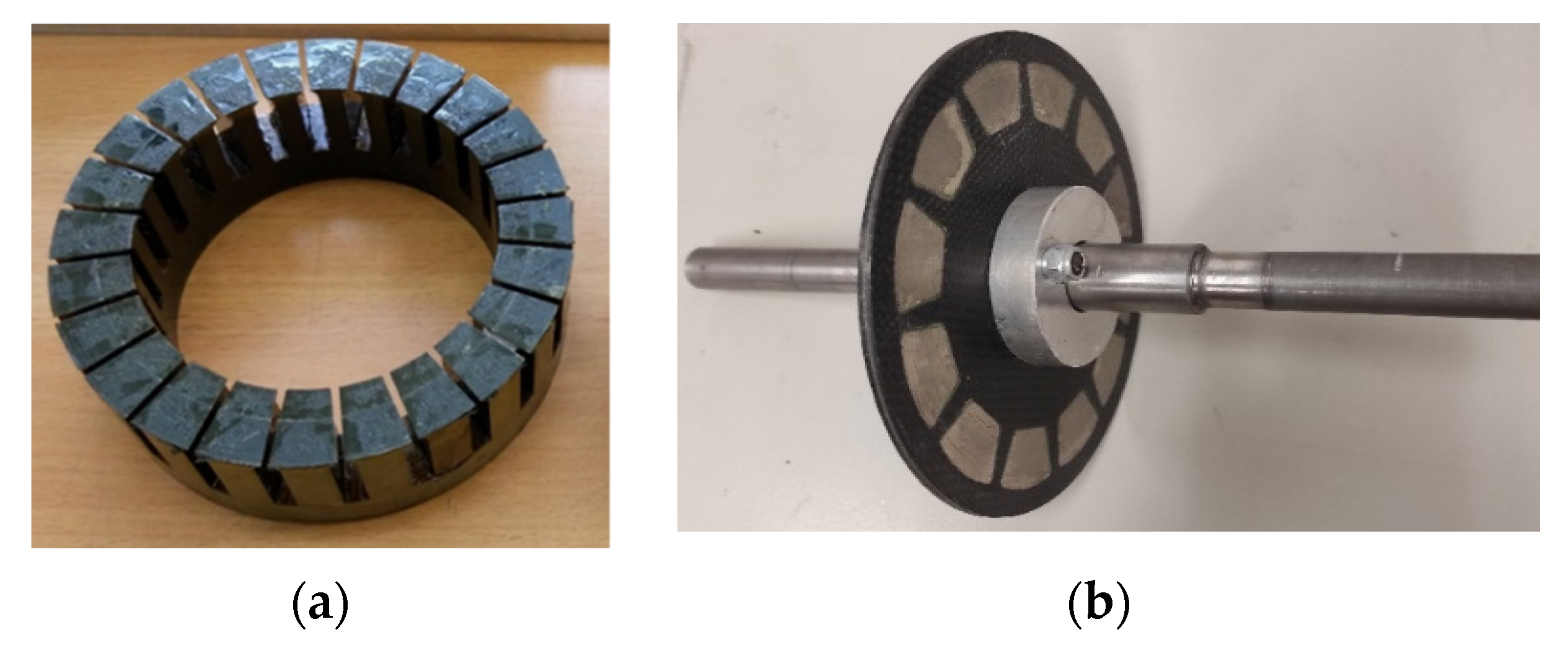
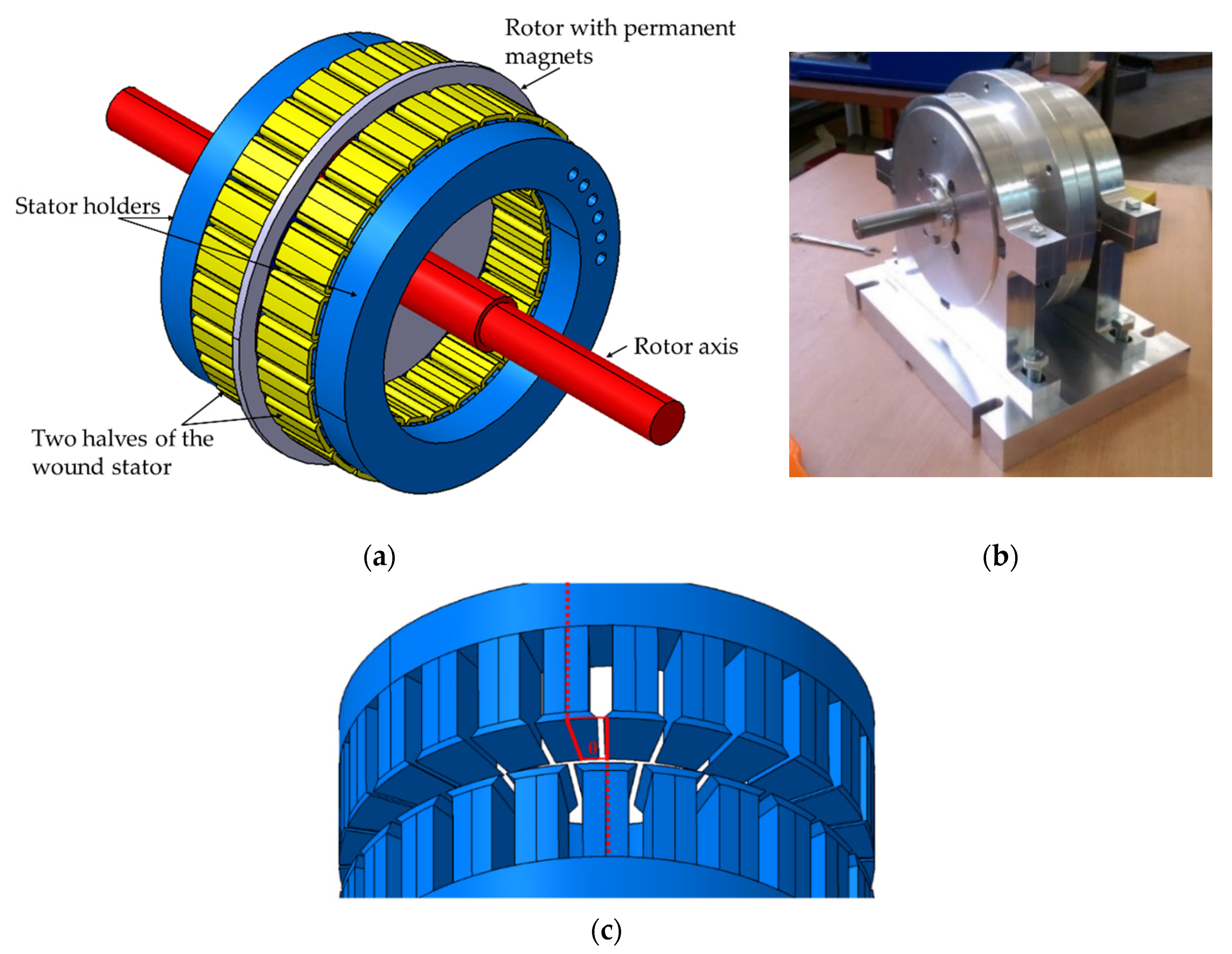
2.1. Prototype Design
- i.
- Stator teeth should consider the dimensions of the PMs.
- ii.
- The teeth dimensions should induce a maximal amount of torque between the stators and the PMs. For this aim, the teeth width should be slightly narrower than the width of a PM.
- iii.
- The stator teeth shoes were made with the optimal dimensions for absorbing maximum magnetic flux.
- i.
- High magnetic flux density relative to weight and size;
- ii.
- Temperature resistant;
- iii.
- Availability and costs;
- iv.
- Stator core size compatibility.
- i.
- Non-metallic isolating material to support (frame) the PMs and eliminate loss due to conductivity of the backing material;
- ii.
- An even number of PMs;
- iii.
- Minimal thickness to reduce the air gap between the stators and the rotor;
- iv.
- Reliable and strong enough to be machined while maintaining tolerances.
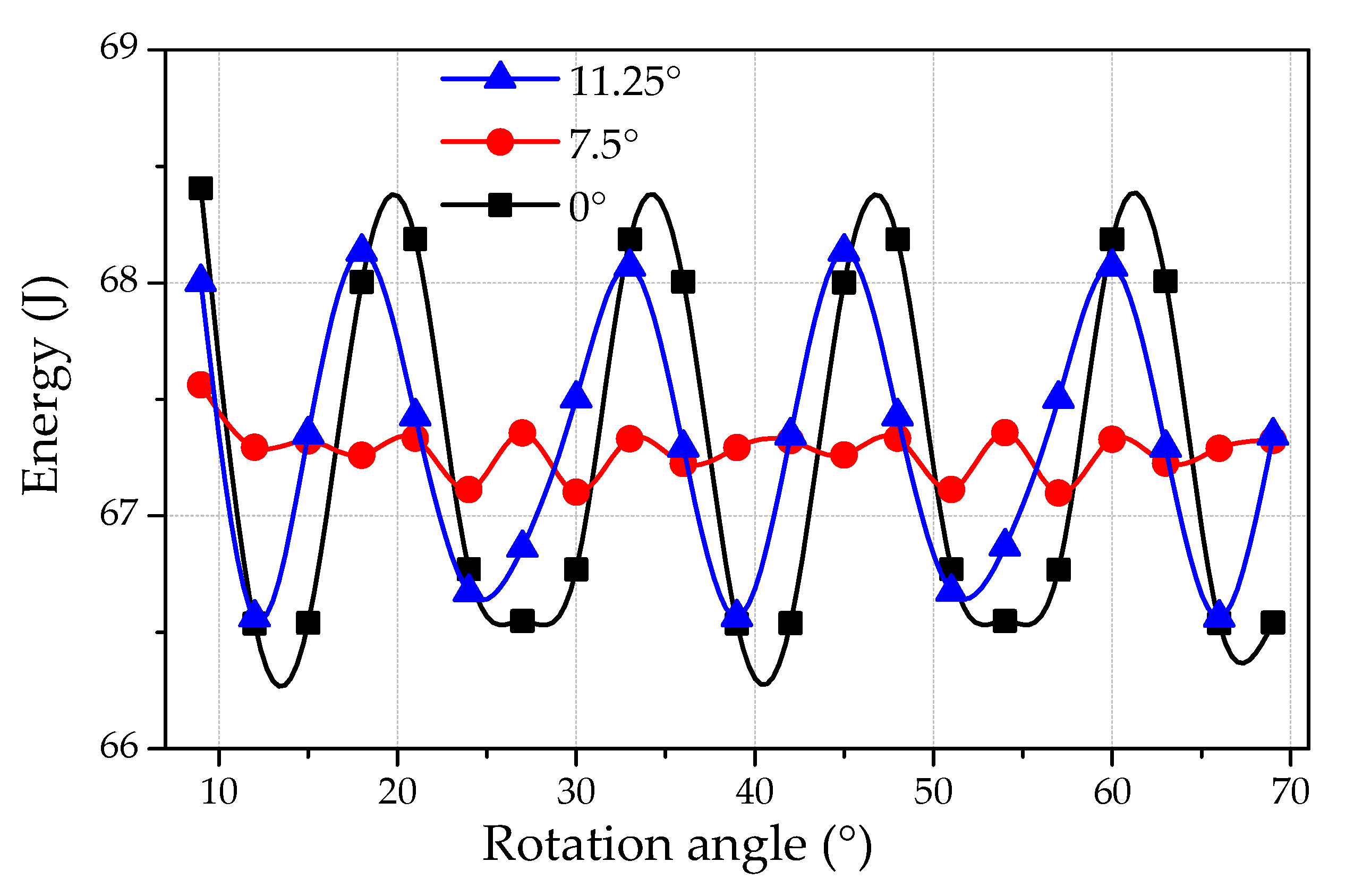
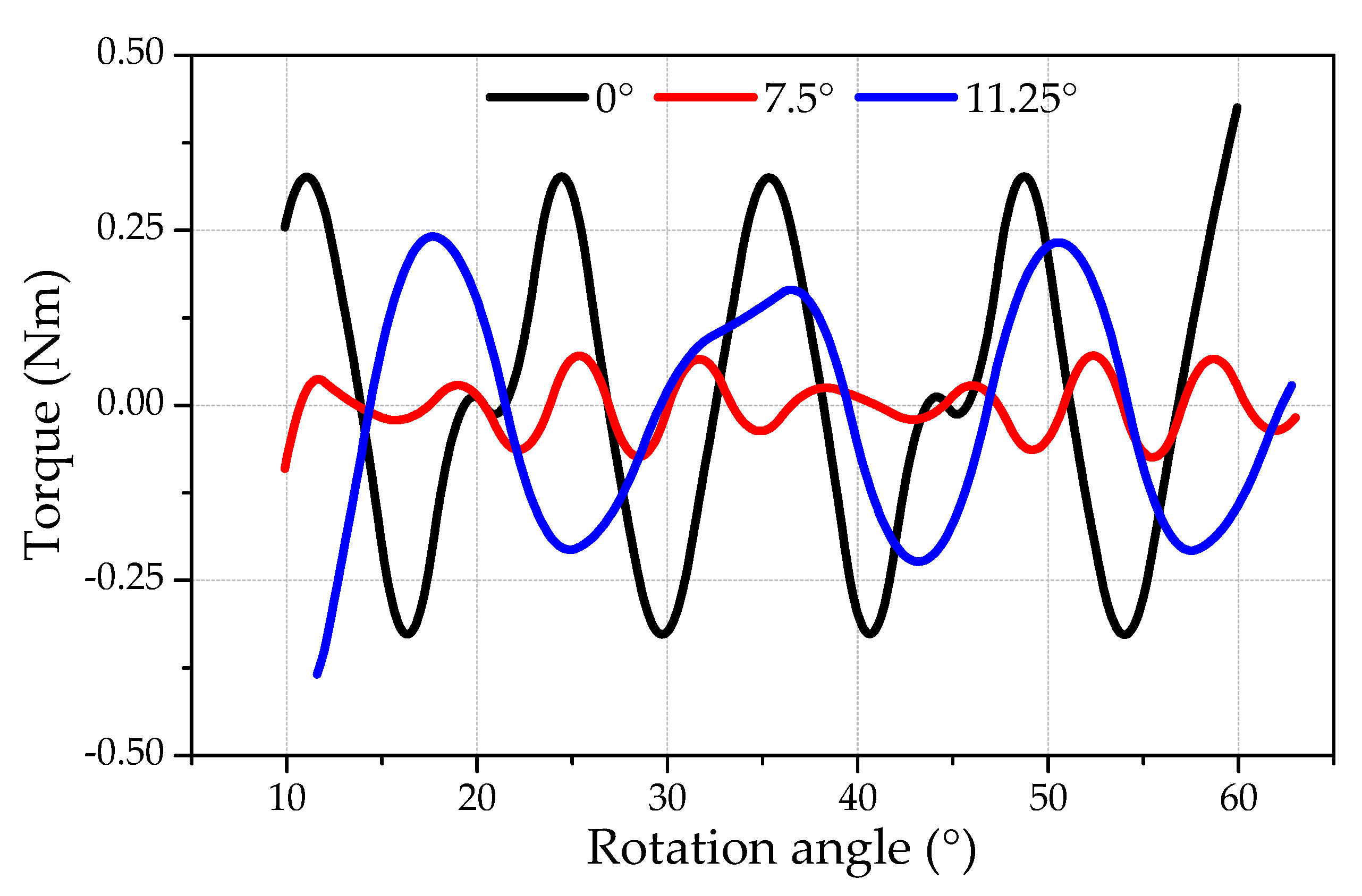
2.2. Analytical Estimation of the Effect of Cogging Torque
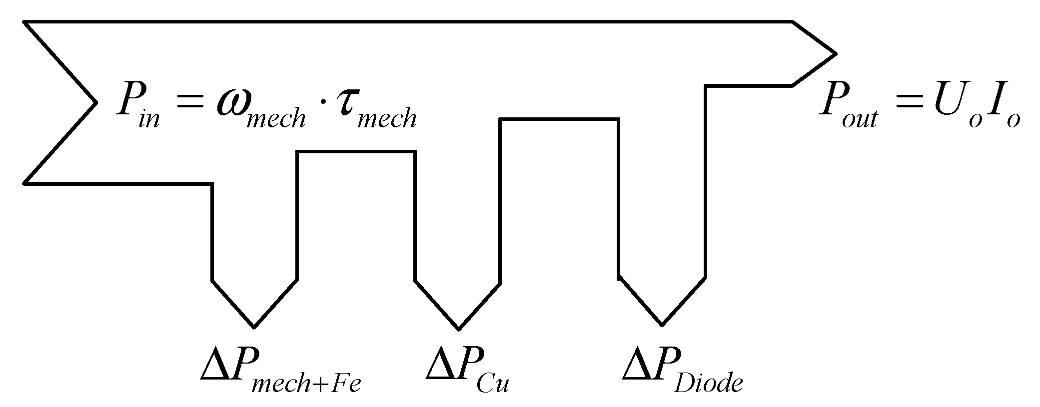
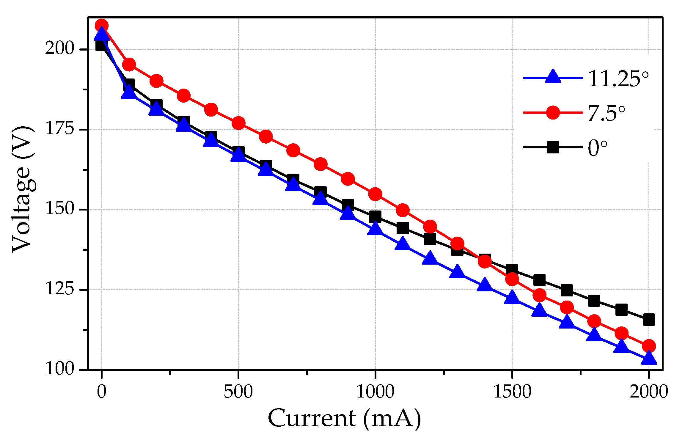
2.3. Output Characteristics
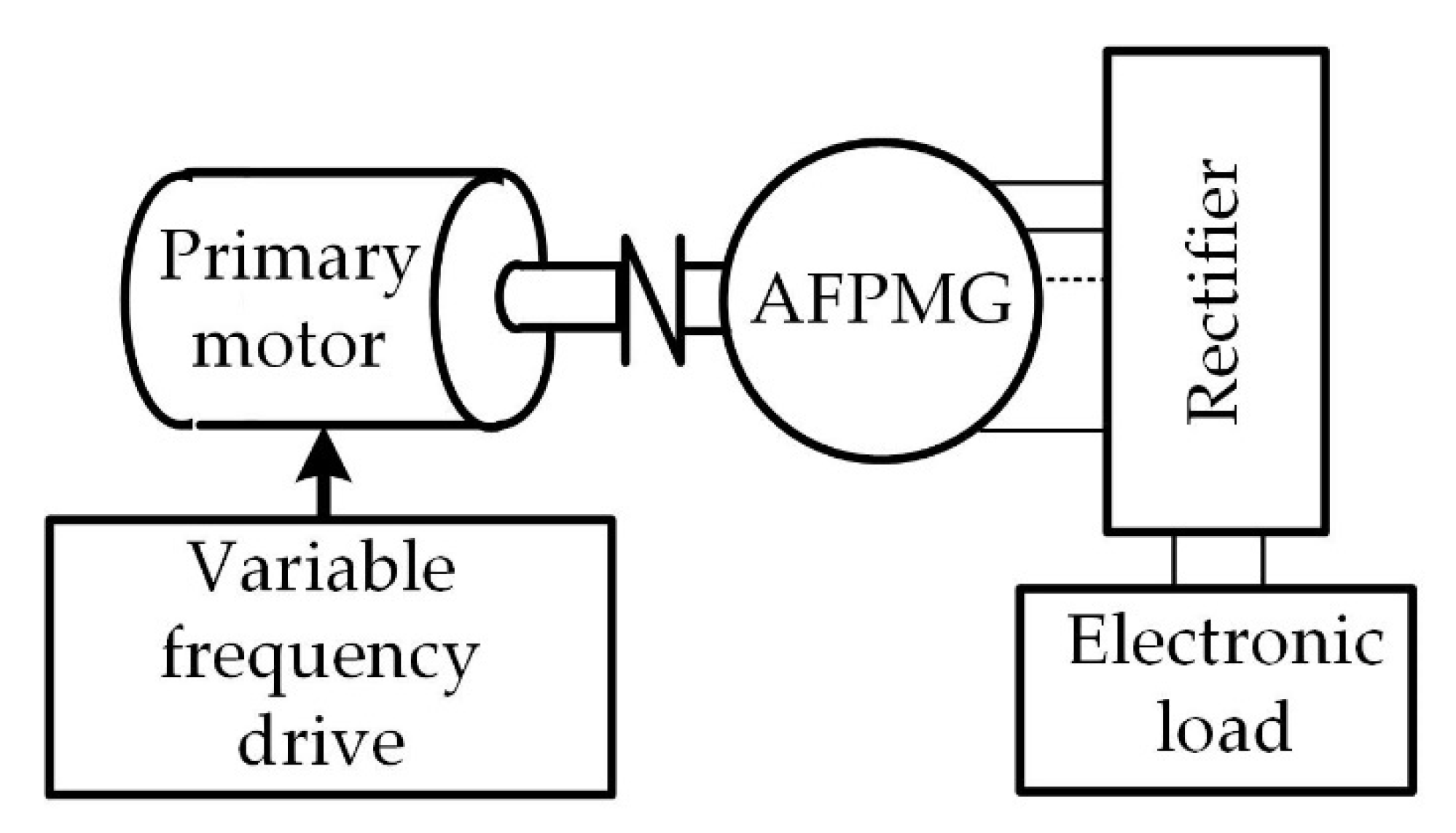
3. Experimental Setup and Methodology
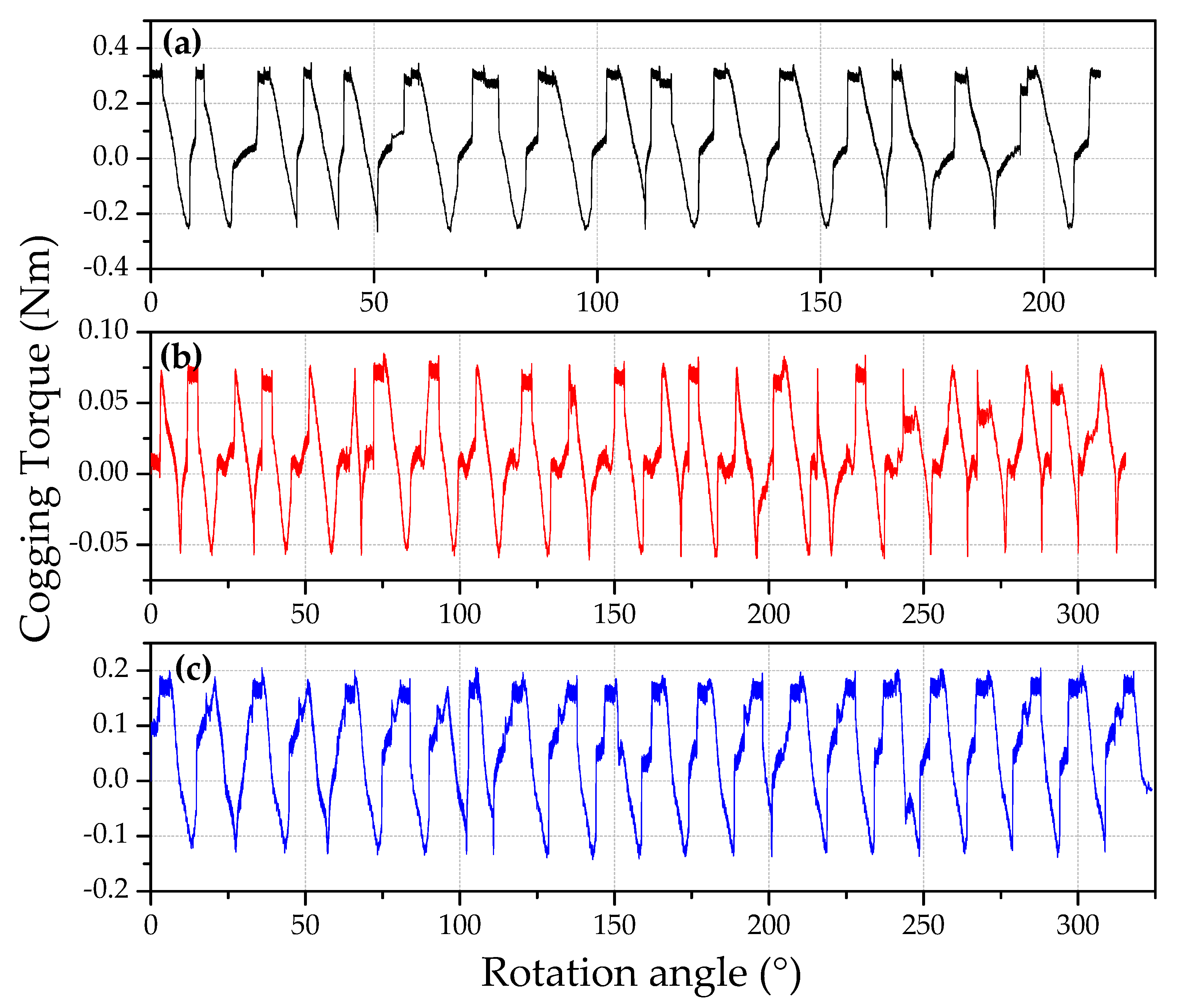
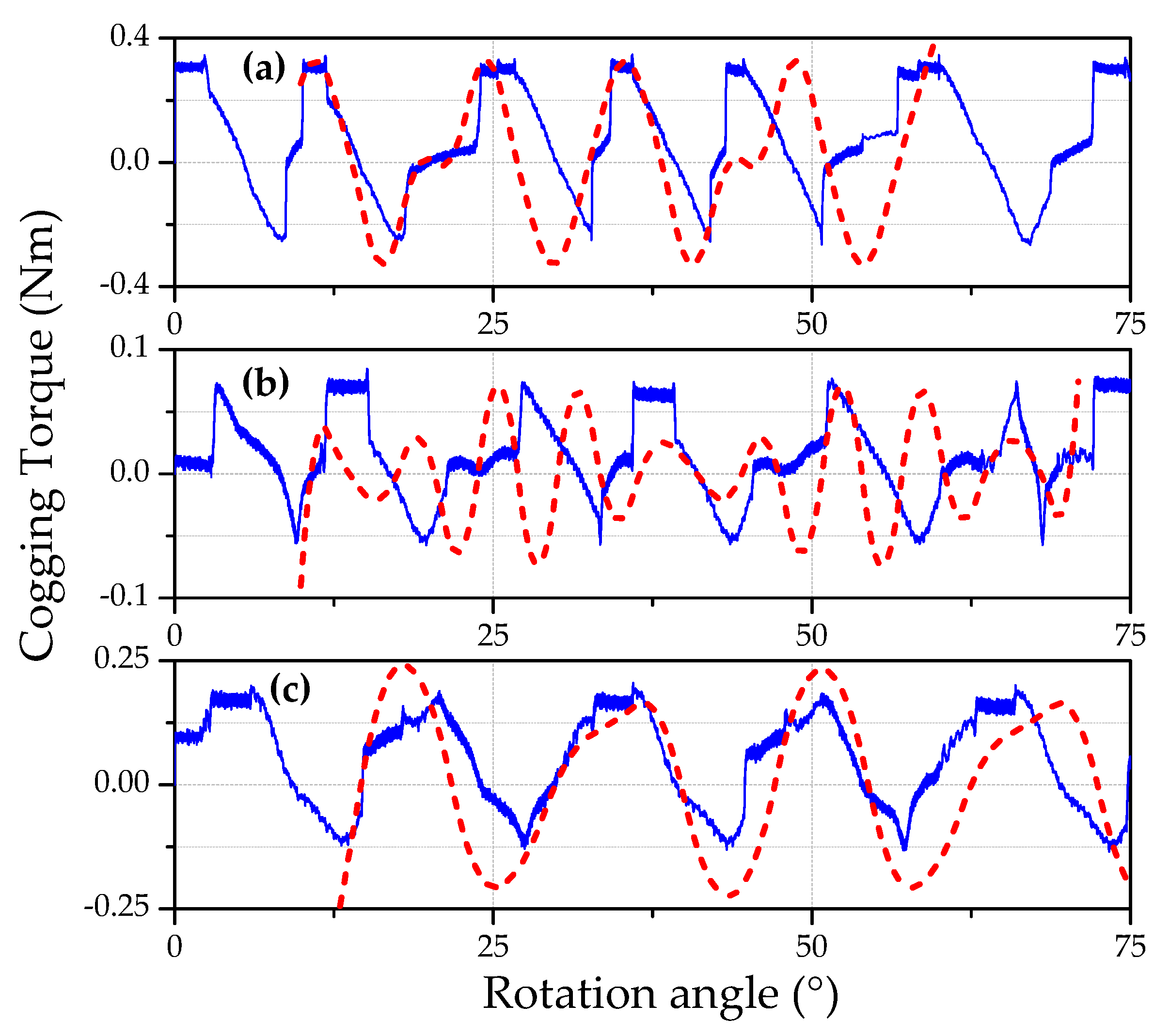
4. Results and Discussion
5. Conclusions
Author Contributions
Funding
Data Availability Statement
Conflicts of Interest
References
- Kahourzade, S.; Mahmoudi, A.; Ping, H.W.; Uddin, M.N. A comprehensive review of axial-flux permanent-magnet machines. Can. J. Electr. Comput. Eng. 2014, 37, 19. [Google Scholar] [CrossRef]
- Radwan-Pragłowska, N.; Węgiel, T.; Borkowski, D. Modeling of Axial Flux Permanent Magnet Generators. Energies 2020, 13, 5741. [Google Scholar] [CrossRef]
- Keskin Arabul, F.; Senol, I.; Oner, Y. Performance Analysis of Axial-Flux Induction Motor with Skewed Rotor. Energies 2020, 13, 4991. [Google Scholar] [CrossRef]
- Pranjić, F.; Virtič, P. Development of Mathematical Models in Explicit Form for Design and Analysis of Axial Flux Permanent Magnet Synchronous Machines. Appl. Sci. 2020, 10, 7695. [Google Scholar] [CrossRef]
- Diab, H.; Amara, Y.; Barakat, G. Open Circuit Performance of Axial Air Gap Flux Switching Permanent Magnet Synchronous Machine for Wind Energy Conversion: Modeling and Experimental Study. Energies 2020, 13, 912. [Google Scholar] [CrossRef] [Green Version]
- Hüner, E.; Zeka, G. Reduction of Cogging Torque and Improvement of Electrical Parameters in Axial Flux Permanent Magnet (AFPM) Synchronous Generator with Experimental Verification. Prog. Electromagn. Res. 2020, 104, 99. [Google Scholar] [CrossRef]
- Liu, C.; Lu, J.; Wang, Y.; Lei, G.; Zhu, J.; Guo, Y. Techniques for Reduction of the Cogging Torque in Claw Pole Machines with SMC Cores. Energies 2017, 10, 1541. [Google Scholar] [CrossRef] [Green Version]
- Laxminarayan, S.S.; Singh, M.; Saifee, A.H.; Mittal, A. Design, modeling and simulation of variable speed axial flux permanent magnet wind generator. Sustain. Energy Technol. Assess. 2017, 19, 114. [Google Scholar] [CrossRef]
- Chan, T.F.; Lai, L.L. An axial-flux permanent-magnet synchronous generator for a direct-coupled wind-turbine system. IEEE Trans. Energy Convers. 2007, 22, 86. [Google Scholar] [CrossRef]
- Holmes, A.S.; Hong, G.; Pullen, K.R. Axial-flux permanent magnet machines for micropower generation. J. Microelectromech. Syst. 2005, 14, 54. [Google Scholar] [CrossRef]
- Tiegna, H.; Amara, Y.; Barakat, G. Study of cogging torque in axial flux permanent magnet machines using an analytical model. IEEE Trans. Magn. 2014, 50, 845. [Google Scholar] [CrossRef]
- Tiegna, H.; Bellara, A.; Amara, Y.; Barakat, G. Analytical modeling of the open-circuit magnetic field in axial flux permanent-magnet machines with semi-closed slots. IEEE Trans. Magn. 2011, 48, 1212. [Google Scholar] [CrossRef]
- Parviainen, A.; Niemela, M.; Pyrhonen, J. Modeling of axial flux permanent-magnet machines. IEEE Trans. Ind. Appl. 2004, 40, 1333. [Google Scholar] [CrossRef]
- Tiegna, H.; Amara, Y.; Barakat, G. A new quasi-3-D analytical model of axial flux permanent magnet machines. IEEE Trans. Magn. 2014, 50, 817. [Google Scholar] [CrossRef]
- Gerber, S.; Wang, R.J. Cogging torque definitions for magnetic gears and magnetically geared electrical machines. IEEE Trans. Magn. 2018, 54, 1. [Google Scholar] [CrossRef]
- Aydin, M.; Zhu, Z.Q.; Lipo, T.A.; Howe, D. Minimization of cogging torque in axial-flux permanent-magnet machines: Design concepts. IEEE Trans. Magn. 2007, 43, 3614. [Google Scholar] [CrossRef]
- Letelier, A.; Tapia, J.A.; Wallace, R.; Valenzuela, A. Cogging torque reduction in an axial flux PM machine with extended speed range. In Proceedings of the IEEE International Conference on Electric Machines and Drives, San Antonio, TX, USA, 15 May 2005; pp. 1261–1267. [Google Scholar]
- Hur, J.; Hyun, D.S.; Hong, J.P. A method for reduction of cogging torque in brushless DC motor considering the distribution of magnetization by 3DEMCN. IEEE Trans. Magn. 1998, 34, 3532. [Google Scholar]
- Lee, G.; Jung, T. Optimal cogging torque reduction design of dual stator radial flux permanent magnet generator. In Proceedings of the 2013 15th European Conference on Power Electronics and Applications, Lille, France, 2–6 September 2013; pp. 1–9. [Google Scholar]
- Islam, M.S.; Mir, S.; Sebastian, T. Issues in reducing the cogging torque of mass-produced permanent-magnet brushless DC motor. IEEE Trans. Ind. Appl. 2004, 40, 813. [Google Scholar] [CrossRef]
- Sikder, C.; Husain, I.; Ouyang, W. Cogging Torque Reduction in Flux-Switching Permanent-Magnet Machines by Rotor Pole Shaping. IEEE Trans. Ind. Appl. 2015, 51, 3609. [Google Scholar] [CrossRef]
- Saygin, A.; Aksöz, A. Design optimization for minimizing cogging torque in Axial Flux Permanent Magnet machines. In Proceedings of the 2017 International Conference on Optimization of Electrical and Electronic Equipment and 2017 Intl Aegean Conference on Electrical Machines and Power Electronics, Brasov, Romania, 25–27 May 2017; pp. 324–329. [Google Scholar]
- Zhu, Z.Q.; Howe, D. Influence Of Design Parameters On Cogging Torque In Permanent Magnet Machines. IEEE Trans. Energy Convers. 2000, 15, 407. [Google Scholar] [CrossRef] [Green Version]
- Islam, R.; Ortega, A.P. Practical aspects of implementing skew angle to reduce cogging torque for the mass-production of permanent magnet synchronous motors. In Proceedings of the 20th International Conference on Electrical Machines and Systems (ICEMS), Sydney, Australia, 11–14 August 2017; pp. 1–5. [Google Scholar]
- Letelier, A.B.; Gonzalez, D.A.; Tapia, J.A.; Wallace, R.; Valenzuela, M.A. Cogging torque reduction in an axial flux PM machine via stator slot displacement and skewing. IEEE Trans. Ind. Appl. 2007, 43, 685. [Google Scholar] [CrossRef]
- Ashabani, M.; Mohamed, Y.A.I. Multiobjective Shape Optimization of Segmented Pole Permanent-Magnet Synchronous Machines With Improved Torque Characteristics. IEEE Trans. Magn. 2011, 47, 795. [Google Scholar] [CrossRef]
- Woo, D.K.; Kim, I.W.; Lim, D.K.; Ro, J.S.; Jung, H.K. Cogging torque optimization of axial flux permanent magnet motor. IEEE Trans. Magn. 2013, 49, 2189. [Google Scholar] [CrossRef]
- Caricchi, F.; Capponi, F.G.; Crescimbini, F.; Solero, L. Experimental study on reducing cogging torque and no-load power loss in axial-flux permanent-magnet machines with slotted winding. IEEE Trans. Ind. Appl. 2004, 40, 1066. [Google Scholar] [CrossRef]
- Caricchi, F.; Capponi, F.G.; Crescimbini, F.; Solero, L. Experimental study on reducing cogging torque and core power loss in axial-flux permanent-magnet machines with slotted winding. In Proceedings of the IEEE Industry Applications Conference. 37th IAS Annual Meeting (Cat. No. 02CH37344), Pittsburgh, PA, USA, 13–18 October 2002; pp. 1295–1302. [Google Scholar]
- Gulec, M.; Aydin, M. Magnet asymmetry in reduction of cogging torque for integer slot axial flux permanent magnet motors. IET Electr. Power Appl. 2014, 8, 189. [Google Scholar] [CrossRef]
- Available online: https://www.comsol.com/ (accessed on 29 October 2019).
- Chapman, S. Electric Machinery Fundamentals; Tata McGraw-Hill Education: New York, NY, USA, 2005. [Google Scholar]
- Hart, D.W. Introduction to Power Electronics; Prentice Hall: Upper Saddle River, NJ, USA, 1997. [Google Scholar]
- Available online: http://www.amos-sensors.com (accessed on 1 December 2020).
- Available online: http://www.maynuo.com/english/xpro.asp?pid=58 (accessed on 3 December 2020).


| Parameters | Range |
|---|---|
| Diameter (mm) | 155 |
| Width (mm) | 95 |
| Weight (kg) | 4.2 |
| Rotational speed range (rpm) | 600–2000 |
| Output power (W) | 110–320 |
| Output voltage (V) | 120–220 |
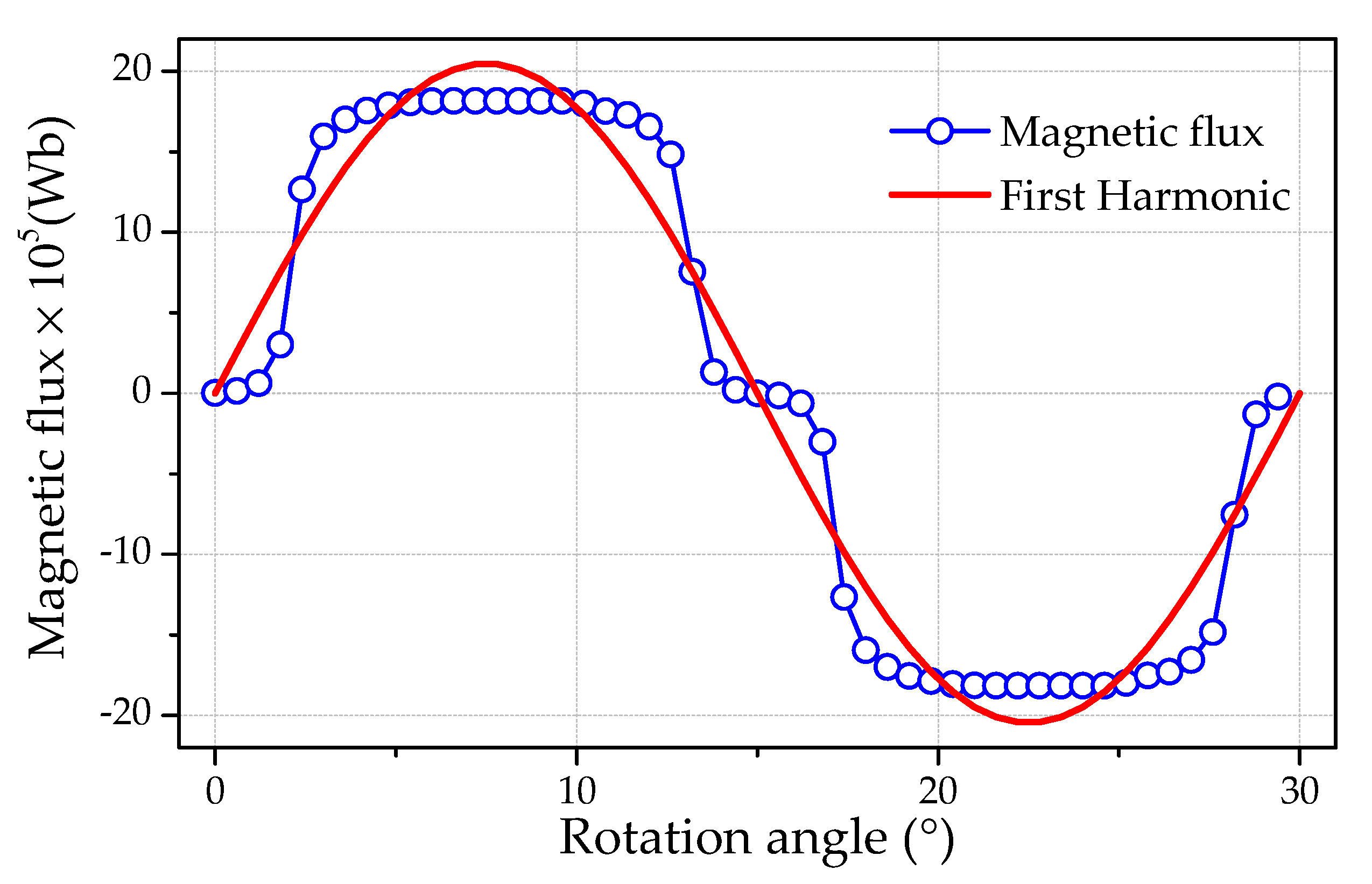
| Shifting Angle (°) | 0 | 7.5 | 11.25 |
| Amplitude × 105 (Wb) | 20.47 | 16.6 | 19.45 |
| Angle (°) | Average Torque | Torque |
|---|---|---|
| 0 | 0.1865 | 0.143 |
| 7.5 | 0.0725 | 0.0737 |
| 11.25 | 0.0978 | 0.089 |
| Velocity (rpm) | Maximum Efficiency | ||
|---|---|---|---|
| 0° | 7.5° | 11.25° | |
| 1200 | 0.705 | 0.749 | 0.700 |
| 1300 | 0.701 | 0.759 | 0.707 |
| 1400 | 0.718 | 0.767 | 0.711 |
| 1500 | 0.739 | 0.759 | 0.739 |
| 1600 | 0.738 | 0.757 | 0.746 |
| 1700 | 0.736 | 0.769 | 0.751 |
| Velocity (rpm) | Maximum Power (W) | ||
|---|---|---|---|
| 0° | 7.5° | 11.25° | |
| 1200 | 146.2 | 156.3 | 148.5 |
| 1300 | 186.0 | 174.4 | 164.0 |
| 1400 | 207.1 | 196.3 | 180.9 |
| 1500 | 230.0 | 211.7 | 199.4 |
| 1600 | 248.1 | 229.4 | 217.3 |
| 1700 | 269.8 | 248.1 | 233.9 |
Publisher’s Note: MDPI stays neutral with regard to jurisdictional claims in published maps and institutional affiliations. |
© 2021 by the authors. Licensee MDPI, Basel, Switzerland. This article is an open access article distributed under the terms and conditions of the Creative Commons Attribution (CC BY) license (http://creativecommons.org/licenses/by/4.0/).
Share and Cite
Mengesha, S.; Rajput, S.; Lineykin, S.; Averbukh, M. The Effects of Cogging Torque Reduction in Axial Flux Machines. Micromachines 2021, 12, 323. https://doi.org/10.3390/mi12030323
Mengesha S, Rajput S, Lineykin S, Averbukh M. The Effects of Cogging Torque Reduction in Axial Flux Machines. Micromachines. 2021; 12(3):323. https://doi.org/10.3390/mi12030323
Chicago/Turabian StyleMengesha, Samuel, Shailendra Rajput, Simon Lineykin, and Moshe Averbukh. 2021. "The Effects of Cogging Torque Reduction in Axial Flux Machines" Micromachines 12, no. 3: 323. https://doi.org/10.3390/mi12030323