
Low Subthreshold Slope AlGaN/GaN MOS-HEMT with Spike-Annealed HfO2 Gate Dielectric

 , , and
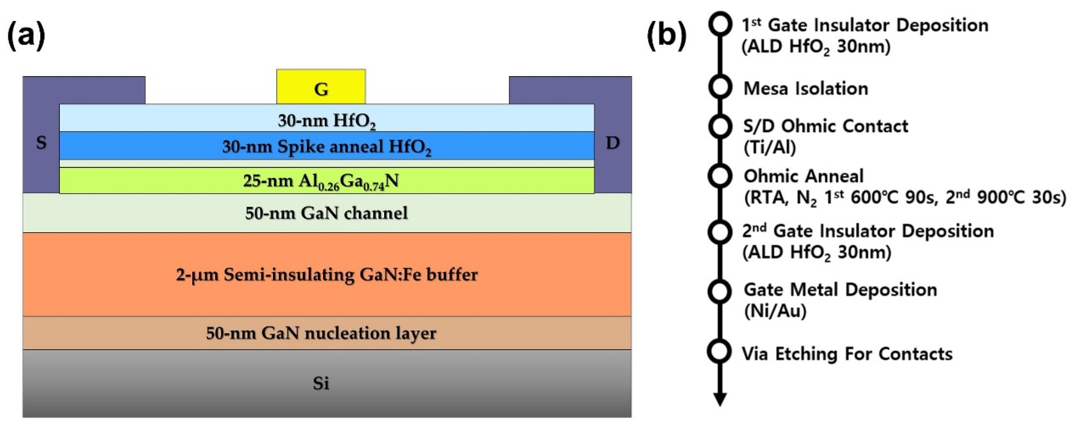
Abstract
:1. Introduction
2. Experimental
3. Results and Discussion
4. Conclusions
Author Contributions
Funding
Data Availability Statement
Acknowledgments
Conflicts of Interest
References
- Chen, K.J.; Häberlen, O.; Lidow, A.; Tsai, C.L.; Ueda, T.; Uemoto, Y.; Wu, Y. GaN-on-Si Power Technology. IEEE Trans. Electron Devices 2017, 64, 779–795. [Google Scholar] [CrossRef]
- Amano, H.; Baines, Y.; Beam, E.; Borga, M.; Bouchet, T.; Chalker, P.R.; Charles, M.; Chen, K.J.; Chowdhury, N.; Chu, R.; et al. The 2018 GaN power electronics roadmap. IOPsci. J. Phys. D Appl. Phys. 2018, 51, 163001. [Google Scholar] [CrossRef]
- Ghosh, S.; Ahsan, S.A.; Dasgupta, A.; Khandelwal, S.; Chauhan, Y.S. GaN HEMT modeling for power and RF applications using ASM-HEMT. In Proceedings of the 2016 3rd International Conference on Emerging Electronics (ICEE), Mumbai, India, 27–30 December 2016; pp. 1–3. [Google Scholar]
- Zanoni, E.; Meneghini, M.; Meneghesso, G.; Bisi, D.; Rossetto, I.; Stocco, A. Reliability and failure physics of GaN HEMT, MIS-HEMT and p-gate HEMTs for power switching applications: Parasitic effects and degradation due to deep level effects and time-dependent breakdown phenomena. In Proceedings of the 2015 IEEE 3rd Workshop on Wide Bandgap Power Devices and Applications (WiPDA), Blacksburg, VA, USA, 2–4 November 2015; pp. 75–80. [Google Scholar]
- An, D.; Lee, B.H.; Lim, B.O.; Lee, M.K.; Kim, S.C.; Oh, J.H.; Kim, S.D.; Park, H.M.; Shin, D.H.; Rhee, J.K. High switching performance 0.1-μm metamorphic HEMTs for low conversion loss 94-GHz resistive mixers. IEEE Electron Device Lett. 2005, 26, 707–709. [Google Scholar]
- Ando, Y.; Kaneki, S.; Hashizume, T. Improved operation stability of Al2O3/AlGaN/GaN MOS high-electron-mobility transistors grown on GaN substrates. Appl. Phys. Express 2019, 12, 024002. [Google Scholar] [CrossRef]
- Shi, Y.T.; Lu, H.; Xu, W.Z.; Zeng, C.K.; Ren, F.F.; Ye, J.D.; Zhou, D.; Chen, D.J.; Zhang, R.; Zheng, Y. High-k HfO2-Based AlGaN/GaN MIS-HEMTs with Y2O3 Interfacial Layer for High Gate Controllability and Interface Quality. IEEE J. Electron Devices Soc. 2020, 8, 15–19. [Google Scholar] [CrossRef]
- Fontserè, A.; Pérez-Tomás, A.; Godignon, P.; Millán, J.; De Vleeschouwer, H.; Parsey, J.M.; Moens, P. Wafer scale and reliability investigation of thin HfO2· AlGaN/GaN MIS-HEMTs. Microelectron. Reliab. 2012, 52, 2220–2223. [Google Scholar] [CrossRef]
- Park, M.H.; Lee, Y.H.; Hwang, C.S. Understanding ferroelectric phase formation in doped HfO2 thin films based on classical nucleation theory. Nanoscale 2019, 11, 19477–19487. [Google Scholar] [CrossRef] [PubMed]
- Kobayashi, M.; Hiramoto, T. On device design for steep-slope negative-capacitance field-effect-transistor operating at sub-0.2V supply voltage with ferroelectric HfO2 thin film. AIP Adv. 2016, 6, 025113. [Google Scholar]
- Tokumitsu, E. Oxide-Channel Ferroelectric-Gate Thin-Film Transistors with Nonvolatile Memory Function. Top. Appl. Phys. 2020, 131, 111–124. [Google Scholar]
- Wu, C.; Ye, H.; Shaju, N.; Smith, J.; Grisafe, B.; Datta, S.; Fay, P. Hf0.5Zr0.5O2-Based Ferroelectric Gate HEMTs with Large Threshold Voltage Tuning Range. IEEE Electron Device Lett. 2020, 41, 337–340. [Google Scholar] [CrossRef]
- Chang, Y.C.; Huang, M.L.; Chang, Y.H.; Lee, Y.J.; Chiu, H.C.; Kwo, J.; Hong, M. Atomic-layer-deposited Al2O3 and HfO2 on GaN: A comparative study on interfaces and electrical characteristics. Microelectron. Eng. 2011, 88, 1207–1210. [Google Scholar] [CrossRef]
- Gunawan, R.; Jung, M.Y.L.; Seebauer, E.G.; Braatz, R.D. Optimal control of rapid thermal annealing in a semiconductor process. J. Process Control 2004, 14, 423–430. [Google Scholar] [CrossRef]
- Lee, C.H.; Yang, J.Y.; Heo, J.S.; Yoo, G.W. Graded Crystalline HfO2 Gate Dielectric Layer for High-k/Ge MOS Gate Stack. IEEE J. Electron Devices Soc. 2021, 9, 295–299. [Google Scholar] [CrossRef]
- Yang, J.Y.; Ma, J.Y.; Lee, C.H.; Yoo, G.W. Polycrystalline/Amorphous HfO2 Bilayer Structure as a Gate Dielectric for β-Ga2O3 MOS Capacitors. IEEE Trans. Electron Devices 2021, 68, 1011–1015. [Google Scholar] [CrossRef]
- Schroeder, U.; Yurchuk, E.; Müller, J.; Martin, D.; Schenk, T.; Polakowski, P.; Adelmann, C.; Popovici, M.I.; Kalinin, S.V.; Mikolajick, T. Important of different dopants on the switching properties of ferroelectric hafnium oxide. IOPsci. J. Phys. D Appl. Phys. 2014, 53, 08LE02. [Google Scholar]
- Sang, X.; Grimley, E.D.; Schenk, T.; Schroeder, U.; Lebeau, J.M. On the structural origins of ferroelectricity in HfO2 thin films. Appl. Phys. Lett. 2015, 106, 162905. [Google Scholar] [CrossRef]
- Polakowski, P.; Müller, J. Ferroelectricity in undoped hafnium oxide. Appl. Phys. Lett. 2015, 106, 232905. [Google Scholar] [CrossRef]
- Nishimura, T.; Xu, L.; Shibayama, S.; Yajima, T.; Migita, S.; Toriumi, A. Ferroelectricity of nondoped thin HfO2 films in TiN/HfO2/TiN stacks. IOPsci. J. Phys. D Appl. Phys. 2016, 55, 08PB01. [Google Scholar]
- Schroder, D.K. Semiconductor Material and Device Characterization; Wiley-IEEE Press: New York, NY, USA, 2006; Volume 3. [Google Scholar]
- Que, T.T.; Zhao, Y.W.; Qiu, Q.L.; Li, L.A.; He, L.; Zhang, J.W.; Feng, C.L.; Liu, Z.X.; Wu, Q.S.; Chen, J. Evaluation of stress voltage on off-state time-dependent breakdown for GaN MIS-HEMT with SiNx gate dielectric. Chin. Phys. B 2020, 29, 107201. [Google Scholar] [CrossRef]
- Scott, J.F.; Kammerdiner, L.; Parris, M.; Traynor, S.; Ottenbacher, V.; Shawabkeh, A.; Oliver, W.F. Switching kinetics of lead zirconate titanate submicron thin-film memories. J. Appl. Phys. 1988, 64, 787–792. [Google Scholar] [CrossRef]
- Moghadam, R.M.; Xiao, Z.; Ahmadi-Majlan, K.; Grimley, E.D.; Bowden, M.; Ong, P.V.; Chambers, S.A.; Lebeau, J.M.; Hong, X.; Sushko, P.V.; et al. An Ultrathin Single Crystalline Relaxor Ferroelectric Integrated on a High Mobility Semiconductor. Nano Lett. 2017, 17, 6248–6257. [Google Scholar] [CrossRef] [PubMed]
- Shen, J.; Zhang, C.Y.; Xu, T.T.; Jiang, A.N.; Zhang, Z.Y.; Wang, S.; Chen, Q. Hysteresis-free HfO2 film grown by atomic layer deposition at low temperature. Thin Solid Films 2011, 519, 7723–7726. [Google Scholar] [CrossRef]
- Zhang, M.; Kong, Y.; Zhou, J.; Xue, F.; Li, L.; Jiang, W.; Hao, L.; Luo, W.; Zeng, H. Polarization and interface charge coupling in ferroelectric/AlGaN/GaN heterostructure. Appl. Phys. Lett. 2012, 100, 112902. [Google Scholar] [CrossRef]


Publisher’s Note: MDPI stays neutral with regard to jurisdictional claims in published maps and institutional affiliations. |
© 2021 by the authors. Licensee MDPI, Basel, Switzerland. This article is an open access article distributed under the terms and conditions of the Creative Commons Attribution (CC BY) license (https://creativecommons.org/licenses/by/4.0/).
Share and Cite
Yeom, M.J.; Yang, J.Y.; Lee, C.H.; Heo, J.; Chung, R.B.K.; Yoo, G. Low Subthreshold Slope AlGaN/GaN MOS-HEMT with Spike-Annealed HfO2 Gate Dielectric. Micromachines 2021, 12, 1441. https://doi.org/10.3390/mi12121441
Yeom MJ, Yang JY, Lee CH, Heo J, Chung RBK, Yoo G. Low Subthreshold Slope AlGaN/GaN MOS-HEMT with Spike-Annealed HfO2 Gate Dielectric. Micromachines. 2021; 12(12):1441. https://doi.org/10.3390/mi12121441
Chicago/Turabian StyleYeom, Min Jae, Jeong Yong Yang, Chan Ho Lee, Junseok Heo, Roy Byung Kyu Chung, and Geonwook Yoo. 2021. "Low Subthreshold Slope AlGaN/GaN MOS-HEMT with Spike-Annealed HfO2 Gate Dielectric" Micromachines 12, no. 12: 1441. https://doi.org/10.3390/mi12121441