Investigating Commercial Filaments for 3D Printing of Stiff and Elastic Constructs with Ligament-Like Mechanics

 , , ,
, , ,
Abstract
:1. Introduction
2. Materials and Methods
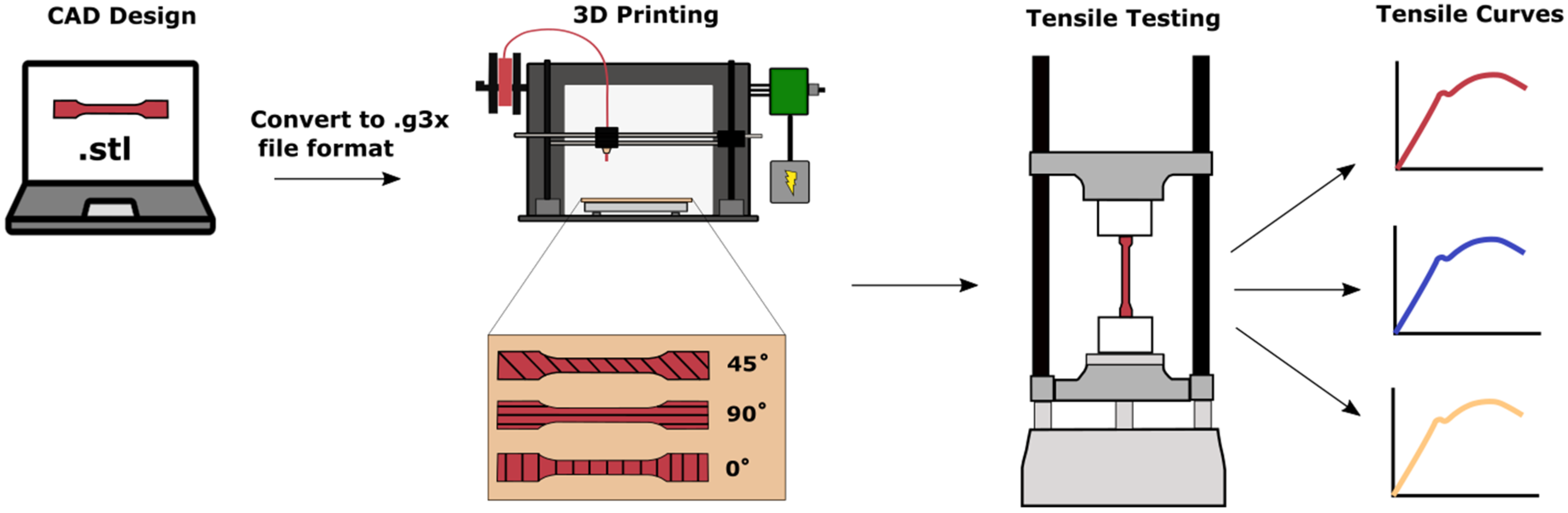
2.1. 3D Printing of Tensile Specimens
2.2. Filaments
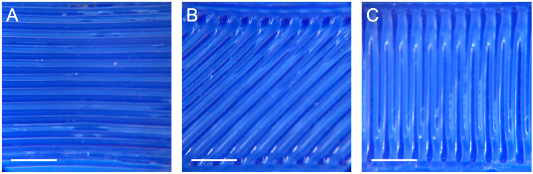
2.3. Light Microscopy
2.4. Mechanical Testing
2.5. Tensile Analysis
2.6. Verification of Gauge Displacement
2.7. Statistical Analyses
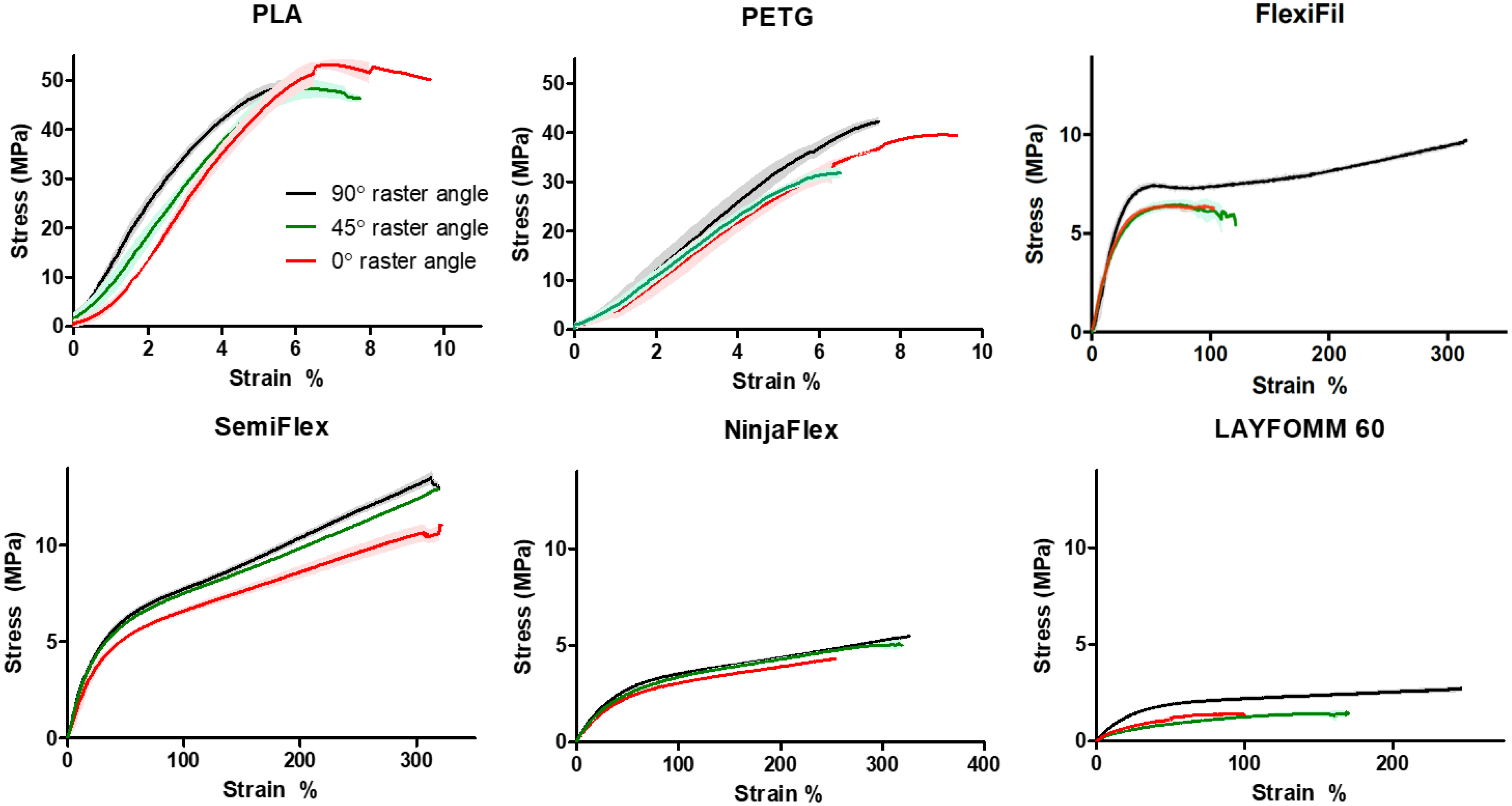
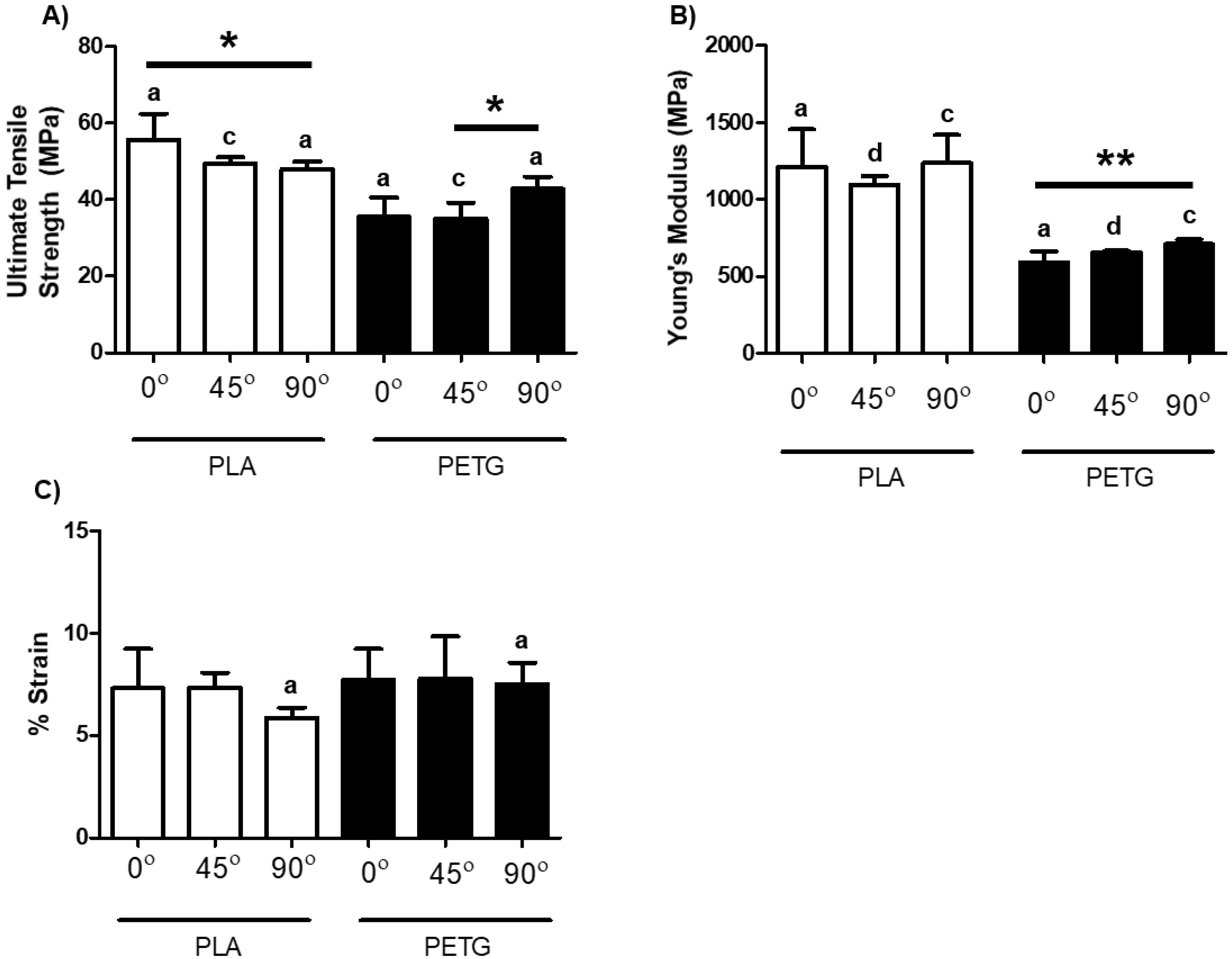
3. Results
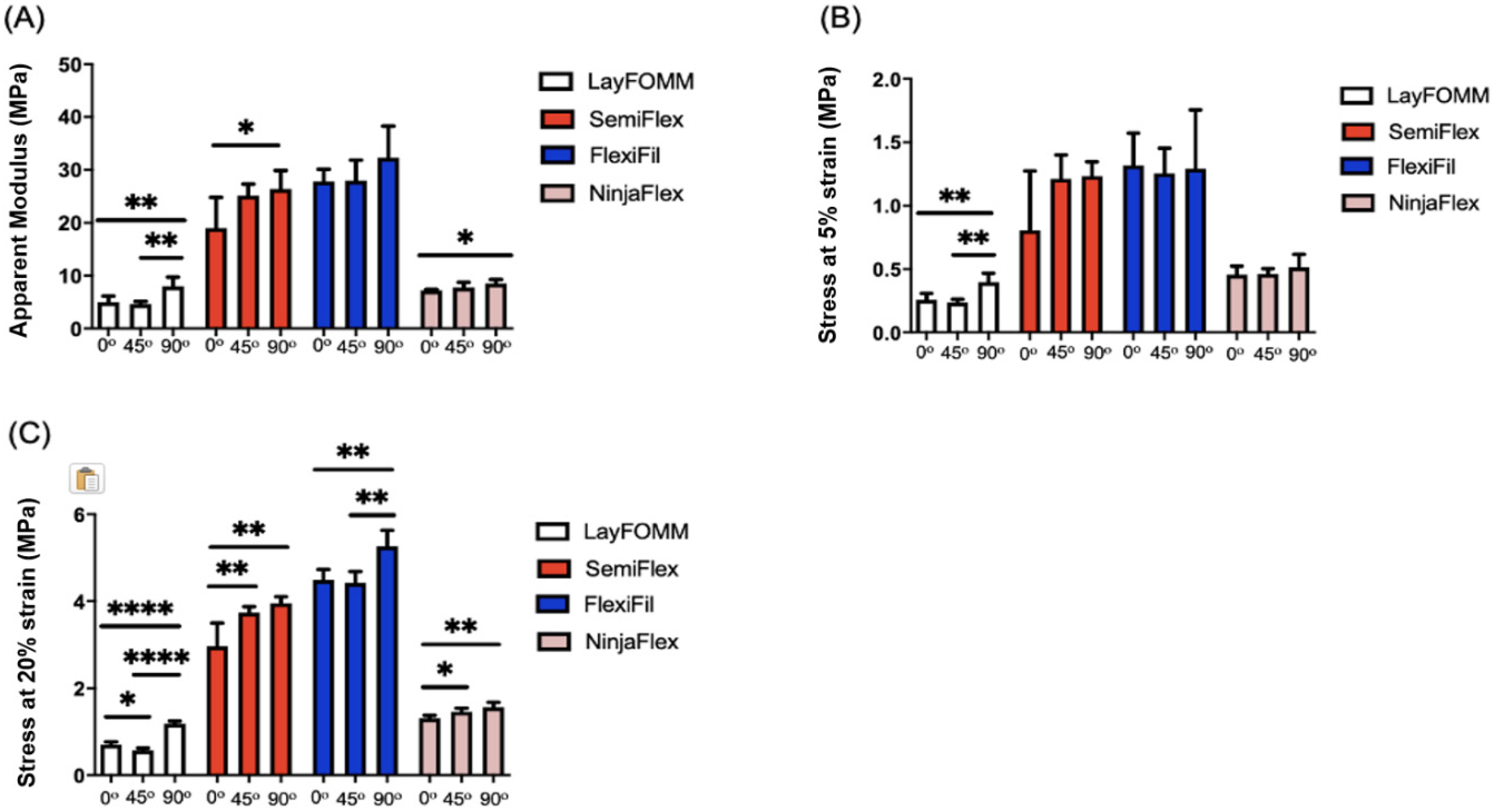
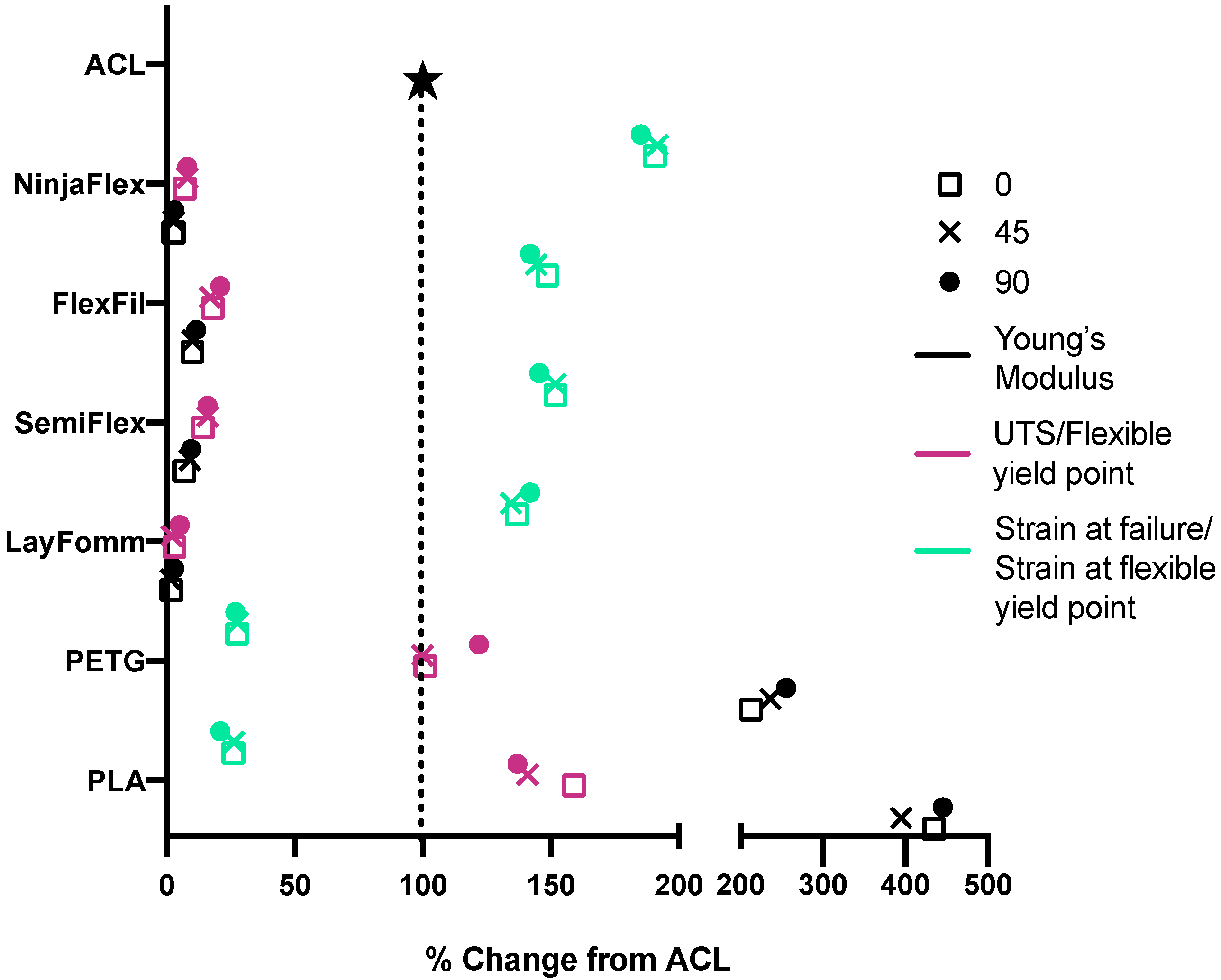
Tensile Properties
4. Discussion
Supplementary Materials
Author Contributions
Funding
Conflicts of Interest
References
- Risberg, M.A.; Lewek, M.; Snyder-Mackler, L. A systematic review of evidence for anterior cruciate ligament rehabilitation: How much and what type? Phys. Ther. Sport 2004, 5, 125–145. [Google Scholar] [CrossRef]
- Butler, D.L.; Noyes, F.R.; Grood, E.S. Ligamentous restraints to anterior-posterior drawer in the human knee. A biomechanical study. J. Bone Jt. Surg. Am. Vol. 1980, 62, 259–270. [Google Scholar] [CrossRef]
- Kiapour, A.M.; Murray, M.M. Basic science of anterior cruciate ligament injury and repair. Bone Jt. Res. 2014, 3, 20–31. [Google Scholar] [CrossRef] [PubMed]
- Gallucci, J. Soccer Injury Prevention and Treatment: A Guide to Optimal Performance for Players, Parents, and Coaches; Demos Medical Publishing: New York, NY, USA, 2014; p. 201. [Google Scholar]
- Marieswaran, M.; Jain, I.; Garg, B.; Sharma, V.; Kalyanasundaram, D. A review on biomechanics of anterior cruciate ligament and materials for reconstruction. Appl. Bionics Biomech. 2018, 2018, 4657824. [Google Scholar] [CrossRef] [PubMed] [Green Version]
- Markatos, K.; Kaseta, M.K.; Lallos, S.N.; Korres, D.S.; Efstathopoulos, N. The anatomy of the acl and its importance in acl reconstruction. Eur. J. Orthop. Surg. Traumatol. Orthop. Traumatol. 2013, 23, 747–752. [Google Scholar] [CrossRef] [PubMed]
- Arnoczky, S.P. Anatomy of the anterior cruciate ligament. Clin. Orthop. Relat. Res. 1983, 172, 19–25. [Google Scholar] [CrossRef]
- Mommersteeg, T.J.; Kooloos, J.G.; Blankevoort, L.; Kauer, J.M.; Huiskes, R.; Roeling, F.Q. The fibre bundle anatomy of human cruciate ligaments. J. Anat. 1995, 187, 461–471. [Google Scholar]
- Welsh, R.P. Knee joint structure and function. Clin. Orthop. Relat. Res. 1980, 147, 7–14. [Google Scholar] [CrossRef]
- Amis, A.A.; Dawkins, G.P. Functional anatomy of the anterior cruciate ligament. Fibre bundle actions related to ligament replacements and injuries. J. Bone Jt. Surg. Br. Vol. 1991, 73, 260–267. [Google Scholar] [CrossRef] [Green Version]
- Norwood, L.A.; Cross, M.J. Anterior cruciate ligament: Functional anatomy of its bundles in rotatory instabilities. Am. J. Sports Med. 1979, 7, 23–26. [Google Scholar] [CrossRef]
- Blackburn, T.A.; Craig, E. Knee anatomy: A brief review. Phys. Ther. 1980, 60, 1556–1560. [Google Scholar] [CrossRef]
- Huebner, P.; Warren, P.B.; Chester, D.; Spang, J.T.; Brown, A.C.; Fisher, M.B.; Shirwaiker, R.A. Mechanical properties of tissue formed in vivo are affected by 3d-bioplotted scaffold microarchitecture and correlate with ecm collagen fiber alignment. Connect. Tissue Res. 2020, 61, 190–204. [Google Scholar] [CrossRef]
- Kwansa, A.L.; Empson, Y.M.; Ekwueme, E.C.; Walters, V.I.; Freeman, J.W.; Laurencin, C.T. Novel matrix based anterior cruciate ligament (acl) regeneration. Soft Matter 2010, 6, 5016. [Google Scholar] [CrossRef]
- Śmigielski, R.; Zdanowicz, U.; Drwięga, M.; Ciszek, B.; Ciszkowska-Łysoń, B.; Siebold, R. Ribbon like appearance of the midsubstance fibres of the anterior cruciate ligament close to its femoral insertion site: A cadaveric study including 111 knees. Knee Surg. Sports Traumatol. Arthrosc. 2015, 23, 3143–3150. [Google Scholar] [CrossRef] [Green Version]
- Korenczuk, C.E.; Votava, L.E.; Dhume, R.Y.; Kizilski, S.B.; Brown, G.E.; Narain, R.; Barocas, V.H. Isotropic failure criteria are not appropriate for anisotropic fibrous biological tissues. J. Biomech. Eng. 2017, 139, 0710081–07100810. [Google Scholar]
- Friel, N.A.; Chu, C.R. The role of acl injury in the development of posttraumatic knee osteoarthritis. Clin. Sports Med. 2013, 32, 1–12. [Google Scholar] [CrossRef]
- Mahapatra, P.; Horriat, S.; Anand, B.S. Anterior cruciate ligament repair—Past, present and future. J. Exp. Orthop. 2018, 5, 1–10. [Google Scholar] [CrossRef] [PubMed] [Green Version]
- Mastrangelo, A.N.; Magarian, E.M.; Palmer, M.P.; Vavken, P.; Murray, M.M. The effect of skeletal maturity on the regenerative function of intrinsic acl cells. J. Orthop. Res. 2010, 28, 644–651. [Google Scholar] [CrossRef] [PubMed] [Green Version]
- Laurent, C.D.; Liu, X.; De Isla, N.; Wang, X.; Rahouadj, R. Defining a scaffold for ligament tissue engineering: What has been done, and what still needs to be done. J. Cell. Immunother. 2018, 4, 4–9. [Google Scholar] [CrossRef]
- Frank, C.B. Ligament structure, physiology and function. J. Musculoskelet. Neuronal Interact. 2004, 4, 199–201. [Google Scholar]
- Crawford, S.N.; Waterman, B.R.; Lubowitz, J.H. Long-term failure of anterior cruciate ligament reconstruction. Arthrosc. J. Arthrosc. Relat. Surg. 2013, 29, 1566–1571. [Google Scholar] [CrossRef]
- Diegel, O. 10.02—Additive manufacturing: An overview. In Comprehensive Materials Processing; Elsevier Ltd.: Oxford, UK, 2014. [Google Scholar]
- Jiménez, M.; Romero, L.; Domínguez, I.A.; Espinosa, M.D.M.; Domínguez, M. Additive manufacturing technologies: An overview about 3d printing methods and future prospects. Complexity 2019, 2019, 1–30. [Google Scholar] [CrossRef] [Green Version]
- Ahangar, P.; Cooke, M.E.; Weber, M.H.; Rosenzweig, D.H. Current biomedical applications of 3d printing and additive manufacturing. Appl Sci. 2019, 9, 1713. [Google Scholar] [CrossRef] [Green Version]
- Haglund, L.; Ahangar, P.; Rosenzweig, D.H. Advancements in 3d printed scaffolds to mimic matrix complexities for musculoskeletal repair. Curr. Opin. Biomed. Eng. 2019, 10, 142–148. [Google Scholar] [CrossRef]
- Gleadall, A.; Visscher, D.; Yang, J.; Thomas, D.; Segal, J. Review of additive manufactured tissue engineering scaffolds: Relationship between geometry and performance. Burns Trauma 2018, 6, 19. [Google Scholar] [CrossRef] [PubMed] [Green Version]
- O’Brien, F.J. Biomaterials & scaffolds for tissue engineering. Mater. Today 2011, 14, 88–95. [Google Scholar]
- Ratcliffe, A.; Butler, D.L.; Dyment, N.A.; Cagle, P.J.; Proctor, C.S.; Ratcliffe, S.S.; Flatow, E.L. Scaffolds for tendon and ligament repair and regeneration. Ann. Biomed. Eng. Soc. 2015, 43, 819–831. [Google Scholar] [CrossRef] [Green Version]
- Lim, W.L.; Liau, L.L.; Ng, M.H.; Chowdhury, S.R.; Law, J.X. Current progress in tendon and ligament tissue engineering. Tissue Eng. Regen. Med. 2019, 16, 549–571. [Google Scholar] [CrossRef]
- Rosenzweig, D.H.; Carelli, E.; Steffen, T.; Jarzem, P.; Haglund, L. 3d-printed abs and pla scaffolds for cartilage and nucleus pulposus tissue regeneration. Int. J. Mol. Sci. 2015, 16, 15118–15135. [Google Scholar] [CrossRef] [Green Version]
- Fairag, R.; Rosenzweig, D.H.; Ramirez-Garcialuna, J.L.; Weber, M.H.; Haglund, L. Three-dimensional printed polylactic acid scaffolds promote bone-like matrix deposition in vitro. ACS Appl. Mater. Interfaces 2019, 11, 15306–15315. [Google Scholar] [CrossRef]
- Alaribe, F.N.; Manoto, S.L.; Motaung, S.C.K.M. Scaffolds from biomaterials: Advantages and limitations in bone and tissue engineering. Biologia 2016, 71, 353–366. [Google Scholar] [CrossRef]
- Eltom, A.; Zhong, G.; Muhammad, A. Scaffold techniques and designs in tissue engineering functions and purposes: A review. Adv. Mater. Sci. Eng. 2019, 2019, 1–13. [Google Scholar] [CrossRef] [Green Version]
- Ahangar, P.; Akoury, E.; Luna, A.S.R.G.; Nour, A.; Weber, M.H.; Rosenzweig, D.H. Nanoporous 3d-printed scaffolds for local doxorubicin delivery in bone metastases secondary to prostate cancer. Materials 2018, 11, 1485. [Google Scholar] [CrossRef] [Green Version]
- TDS. NinjaFlex; Fenner Inc.: Manheim, PA, USA, 2016; Available online: https://ninjatek.com/wp-content/uploads/2019/10/NinjaFlex-TDS.pdf (accessed on 9 March 2020).
- TDS. NinjaFlex SemiFlex; Fenner Inc.: Manheim, PA, USA, 2016; Available online: https://www.3dmensionals.de/media/pdf/cf/33/7e/SemiFlex-TDS.pdf (accessed on 9 March 2020).
- TDS. FlexiFil; Formfutura BV: Nijmegan, The Netherlands; Available online: https://gzhls.at/blob/ldb/0/4/1/7/4ddb1d5c17caa564a350f22266fb04ae1b39.pdf (accessed on 9 March 2020).
- TDS. PLA; SD3D Printing: San Diego, CA, USA; Available online: https://www.sd3d.com/wp-content/uploads/2017/06/MaterialTDS-PLA_01.pdf (accessed on 9 March 2020).
- TDS. PETG; SD3D Printing: San Diego, CA, USA; Available online: https://www.sd3d.com/wp-content/uploads/2017/06/MaterialTDS-PETG_01.pdf (accessed on 9 March 2020).
- Takeda, Y.; Xerogeanes, J.W.; Livesay, G.A.; Fu, F.H.; Woo, S.L.Y. Biomechanical function of the human anterior cruciate ligament. J. Arthrosc. Relat. Surg. 1994, 10, 140–147. [Google Scholar] [CrossRef]
- Chandrashekar, N.; Mansouri, H.; Slauterbeck, J.; Hashemi, J. Sex-based differences in the tensile properties of the human anterior cruciate ligament. J. Biomech. 2006, 39, 2943–2950. [Google Scholar] [CrossRef]
- Parrado-Agudelo, J.Z.; Narváez-Tovar, C. Mechanical characterization of polylactic acid, polycaprolactone and lay-fomm 40 parts manufactured by fused deposition modeling, as a function of the printing parameters. ITECKNE 2019, 16, 25–31. [Google Scholar] [CrossRef] [Green Version]
- Fleming, B.C.; Beynnon, B.D. In vivo measurement of ligament/tendon strains and forces: A review. Ann. Biomed. Eng. 2004, 32, 318–328. [Google Scholar] [CrossRef]
- Beynnon, B.D.; Fleming, B.C. Anterior cruciate ligament strain in-vivo: A review of previous work. J. Biomech. 1998, 31, 519–525. [Google Scholar] [CrossRef]
- Sheehan, F.T.; Rebmann, A. Non-invasive, in vivo measures of anterior cruciate ligament strains. Trans. in Orthop. Res. Soc. 2003, 28, 264. [Google Scholar]
- Butler, D.L.; Guan, Y.; Kay, M.D.; Cummings, J.F.; Feder, S.M.; Levy, M.S. Location-dependent variations in the material properties of the anterior cruciate ligament. J. Biomech. 1992, 25, 511–518. [Google Scholar] [CrossRef]
- Bružauskaitė, I.; Bironaitė, D.; Bagdonas, E.; Bernotienė, E. Scaffolds and cells for tissue regeneration: Different scaffold pore sizes—Different cell effects. Cytotechnol. Inc. Methods Cell Sci. Int. J.Cell Cult. Biotechnol. 2016, 68, 355–369. [Google Scholar]
- Akoury, E.; Weber, M.H.; Rosenzweig, D.H. 3d-printed nanoporous scaffolds impregnated with zoledronate for the treatment of spinal bone metastases. MRS Adv. 2019, 4, 1245–1251. [Google Scholar] [CrossRef]
- Wang, S.; Zhong, S.; Lim, C.T.; Nie, H. Effects of fiber alignment on stem cells–fibrous scaffold interactions. J. Mater. Chem. B 2015, 3, 3358–3366. [Google Scholar] [CrossRef]
- Brown, R.A.; Prajapati, R.; McGrouther, D.A.; Yannas, I.V.; Eastwood, M. Tensional homeostasis in dermal fibroblasts: Mechanical responses to mechanical loading in three-dimensional substrates. J. Cell. Physiol. 1998, 175, 323–332. [Google Scholar] [CrossRef]
- Wang, J.H.C.; Jia, F.; Gilbert, T.W.; Woo, S.L.Y. Cell orientation determines the alignment of cell-produced collagenous matrix. J. Biomech. 2003, 36, 97–102. [Google Scholar] [CrossRef]
- Tanikella, N.G.; Wittbrodt, B.; Pearce, J.M. Tensile strength of commercial polymer materials for fused filament fabrication 3d printing. Addit. Manuf. 2017, 15, 40–47. [Google Scholar] [CrossRef] [Green Version]
- Perego, G.; Cella, G.D.; Bastioli, C. Effect of molecular weight and crystallinity on poly(lactic acid) mechanical properties. J. Appl. Polym. Sci. 1996, 59, 37–43. [Google Scholar] [CrossRef]
- Wittbrodt, B.; Pearce, J.M. The effects of pla color on material properties of 3-d printed components. Addit. Manuf. 2015, 8, 110–116. [Google Scholar] [CrossRef] [Green Version]
- Wimpenny, D.I.; Pandey, P.M.; Kumar, L.J. Advances in 3d Printing & Additive Manufacturing Technologies; Springer: Singapore, 2016. [Google Scholar]
- Balani, K.; Verma, V.; Agarwal, A.; Narayan, R. Biosurfaces: A Materials Science and Engineering Perspective; John Wiley & Sons, Inc.: Hoboken, NJ, USA, 2015; p. 338. [Google Scholar]
- Mar, D.E.; Clary, S.J.; Burton, D.C.; McIff, T.E. Biomechanics of prophylactic tethering for proximal junctional kyphosis: Characterization of spinous process tether pretensioning and pull-out force. Spine Deform. 2019, 7, 191–196. [Google Scholar] [CrossRef]
- Petersen, W.; Rembitzki, I.V.; Koppenburg, A.G.; Ellermann, A.; Liebau, C.; Brüggemann, G.P.; Best, R. Treatment of acute ankle ligament injuries: A systematic review. Arch. Orthop. Trauma Surg. 2013, 133, 1129–1141. [Google Scholar] [CrossRef] [Green Version]
- Andersson, J.K.; Rööser, B.; Karlsson, J. Level of evidence in wrist ligament repair and reconstruction research: A systematic review. J. Exp. Orthop. 2018, 5, 1–8. [Google Scholar] [CrossRef] [PubMed] [Green Version]


| Material | Yield Tensile Strength (MPa) | Ultimate Tensile Strength (MPa) | Tensile Modulus (MPa) | Manufacturer Datasheet |
|---|---|---|---|---|
| NinjaFlex | 4 | 26 | 12 | [36] |
| SemiFlex | 9 | 43 | 25 | [37] |
| FlexiFil | 24 | 95 | [38] | |
| PLA | 35.9 | 26.4 | 2300 | [39] |
| PETG | 53 | 2100 | [40] |
| Material | Nozzle Temperature (°C) | Bed Temperature (°C) | Initial Layer Speed (mm/s) | Speed (mm/s) |
|---|---|---|---|---|
| PLA | 205 | 70 | 17.5 | 35 |
| PETG | 240 | 80 | 17.5 | 35 |
| SemiFlex | 215 | 50 | 15 | 30 |
| FlexiFil | 215 | 55 | 15 | 30 |
| NinjaFlex | 230–240 | 55 | 10 | 15 |
| Lay FOMM 60 | 220–225 | 50 | 15 | 25 |
| Material | Effect of Raster Angle on Mechanical Properties | ||
|---|---|---|---|
| UTS | Young’s Modulus | Strain at Failure | |
| PLA | 0.0300 | 0.6114 | 0.0280 |
| PETG | 0.0232 | 0.0053 | 0.9606 |
| Material | Effect of Raster Angle on Mechanical Properties | ||||
|---|---|---|---|---|---|
| Apparent Modulus | 5% Strain | 20% Strain | 50% Strain | 100% Strain | |
| Lay FOMM 60 | 0.0018 | 0.0008 | <0.0001 | 0.0193 | N/A |
| SemiFlex | 0.0323 | 0.0746 | 0.0012 | 0.0006 | 0.0003 |
| FlexiFil | 0.2166 | 0.8273 | 0.0012 | 0.0119 | 0.0471 |
| NinjaFlex | 0.0489 | 0.4141 | 0.0028 | 0.0019 | <0.0001 |
| Material | Mechanical Properties | |||
|---|---|---|---|---|
| Raster Angle (°) | Young’s Modulus (MPa) | UTS/Flexible Yield Point (MPa) | Strain at Failure/Strain at Flexible Yield (%) | |
| PLA | 0 | 1208 | 55.72 | 7.301 |
| 45 | 1098 | 49.43 | 7.347 | |
| 90 | 1238 | 47.98 | 5.857 | |
| PETG | 0 | 591.6 | 35.50 | 7.731 |
| 45 | 656.3 | 34.96 | 7.786 | |
| 90 | 710.7 | 42.85 | 7.509 | |
| Lay FOMM 60 | 0 | 5.040 | 1.017 | 38.27 |
| 45 | 4.622 | 0.8152 | 37.69 | |
| 90 | 7.992 | 1.711 | 39.76 | |
| SemiFlex | 0 | 18.98 | 4.822 | 42.53 |
| 45 | 25.16 | 5.605 | 42.47 | |
| 90 | 26.39 | 5.687 | 40.75 | |
| FlexiFil | 0 | 27.82 | 6.129 | 41.63 |
| 45 | 27.96 | 5.992 | 40.39 | |
| 90 | 32.30 | 7.189 | 39.75 | |
| NinjaFlex | 0 | 7.244 | 2.404 | 53.38 |
| 45 | 7.768 | 2.650 | 53.70 | |
| 90 | 8.505 | 2.797 | 51.85 | |
| ACL | - | 278 [40] | 35 [40] | 28 [41] |
© 2020 by the authors. Licensee MDPI, Basel, Switzerland. This article is an open access article distributed under the terms and conditions of the Creative Commons Attribution (CC BY) license (http://creativecommons.org/licenses/by/4.0/).
Share and Cite
Pitaru, A.A.; Lacombe, J.-G.; Cooke, M.E.; Beckman, L.; Steffen, T.; Weber, M.H.; Martineau, P.A.; Rosenzweig, D.H. Investigating Commercial Filaments for 3D Printing of Stiff and Elastic Constructs with Ligament-Like Mechanics. Micromachines 2020, 11, 846. https://doi.org/10.3390/mi11090846
Pitaru AA, Lacombe J-G, Cooke ME, Beckman L, Steffen T, Weber MH, Martineau PA, Rosenzweig DH. Investigating Commercial Filaments for 3D Printing of Stiff and Elastic Constructs with Ligament-Like Mechanics. Micromachines. 2020; 11(9):846. https://doi.org/10.3390/mi11090846
Chicago/Turabian StylePitaru, Audrey A., Jean-Gabriel Lacombe, Megan E. Cooke, Lorne Beckman, Thomas Steffen, Michael H. Weber, Paul A. Martineau, and Derek H. Rosenzweig. 2020. "Investigating Commercial Filaments for 3D Printing of Stiff and Elastic Constructs with Ligament-Like Mechanics" Micromachines 11, no. 9: 846. https://doi.org/10.3390/mi11090846