Light Extraction Analysis of AlGaInP Based Red and GaN Based Blue/Green Flip-Chip Micro-LEDs Using the Monte Carlo Ray Tracing Method


Abstract
:1. Introduction
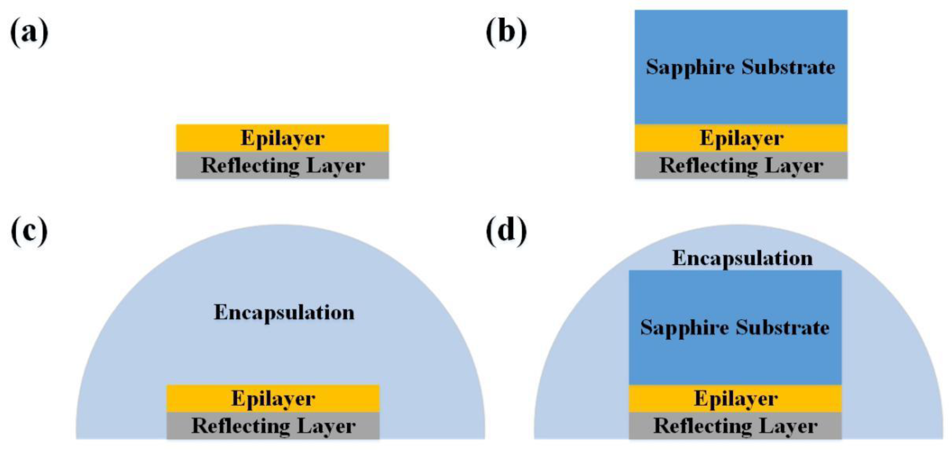
2. Simulation Model
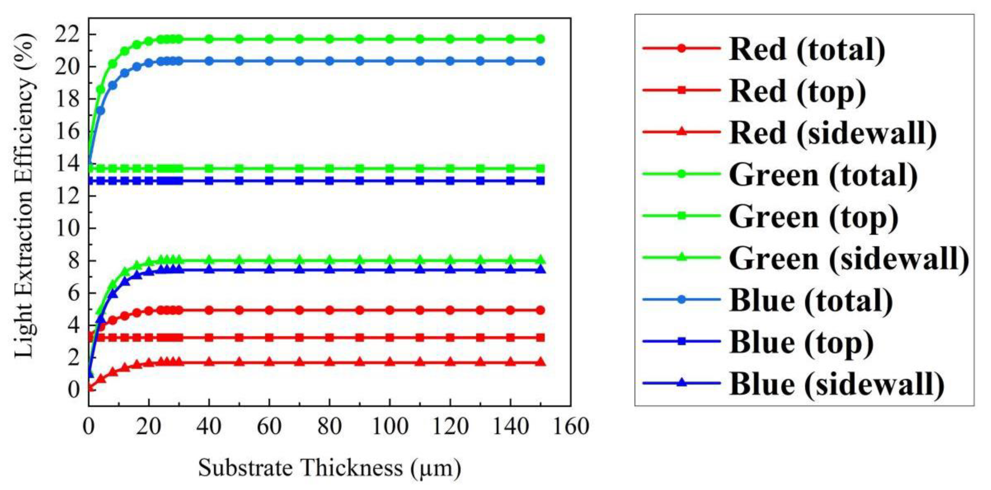
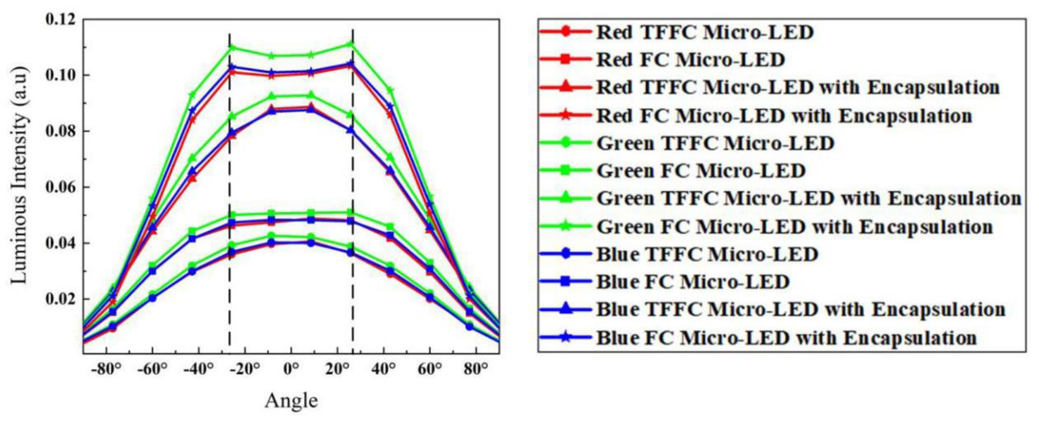
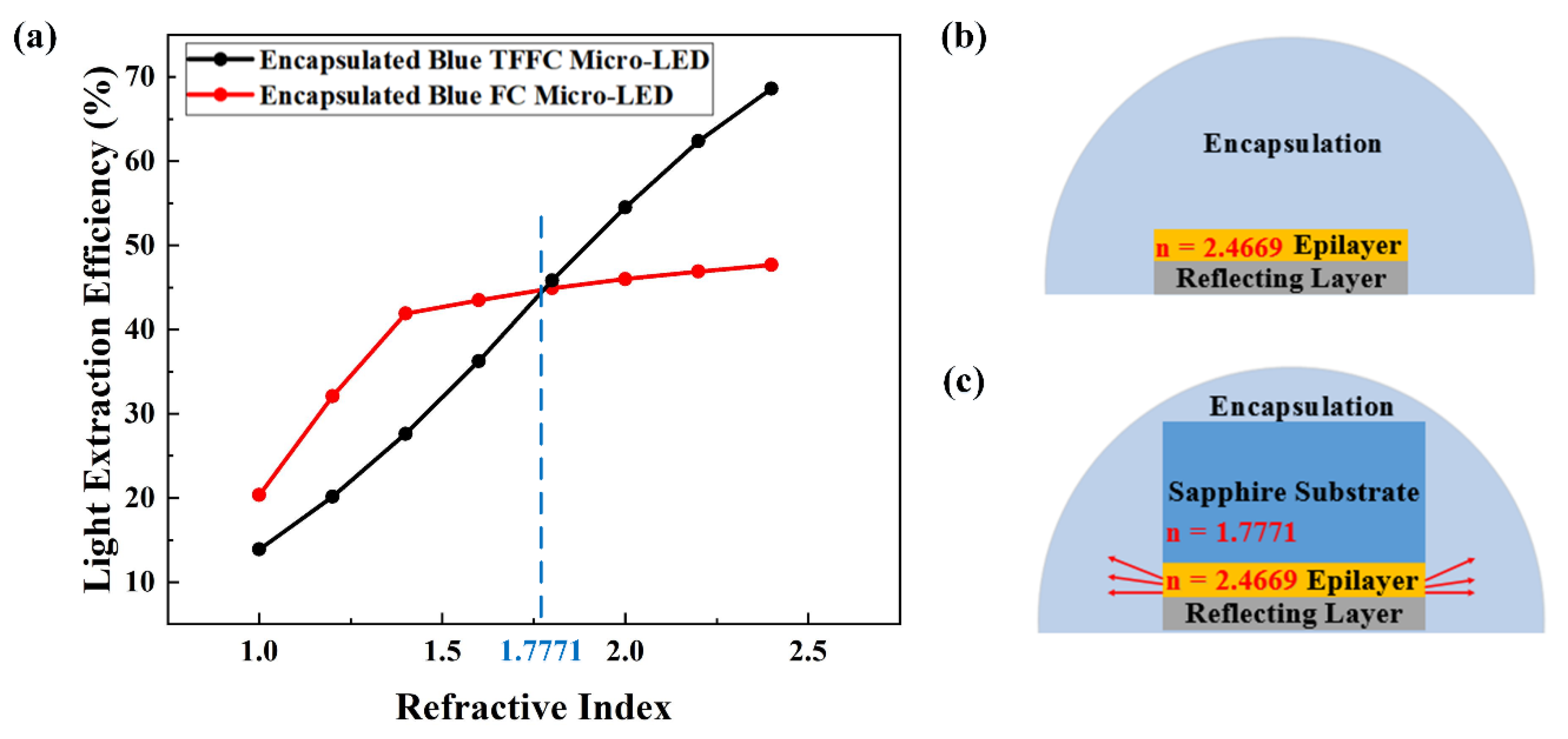
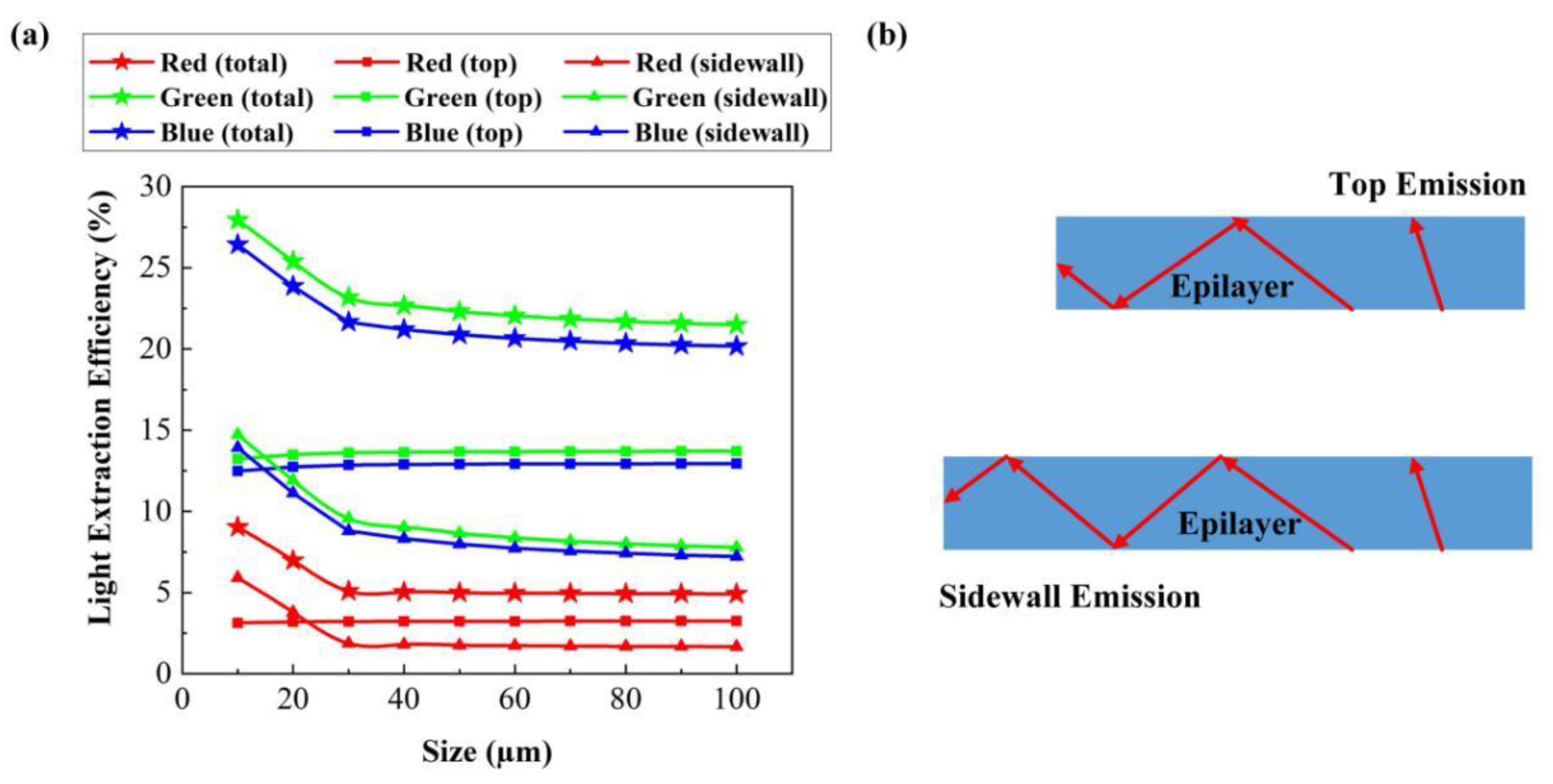
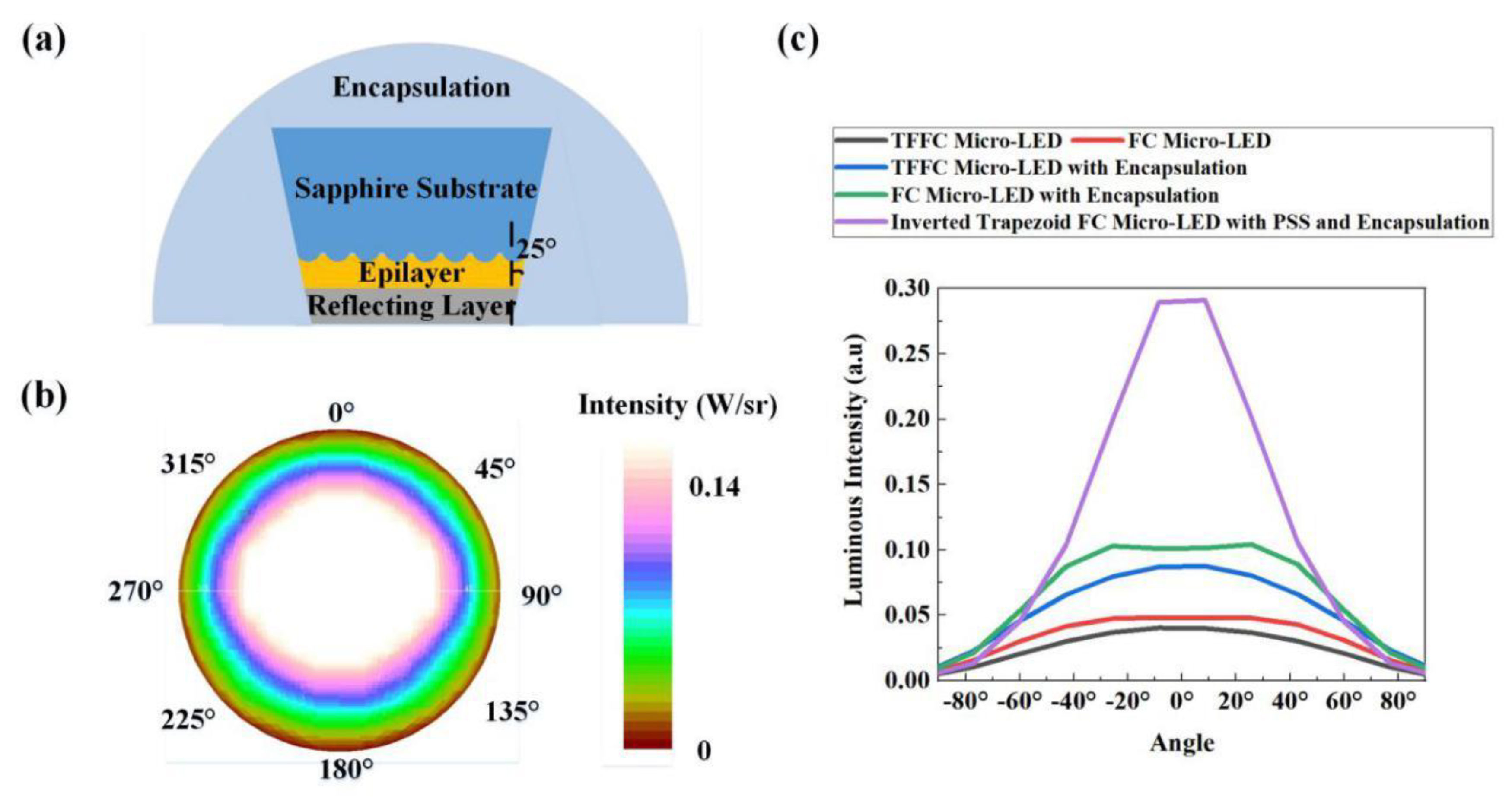
3. Results and Discussion
4. Conclusions
Author Contributions
Funding
Conflicts of Interest
References
- Yang, S.M.; Wang, P.H.; Chao, C.H.; Chu, C.W.; Yeh, Y.T.; Chen, Y.S.; Chang, F.P.; Fang, Y.H.; Lin, C.C.; Wu, C.I. Angular color variation in micron-scale light-emitting diode arrays. Opt. Express 2019, 27, A1308–A1323. [Google Scholar] [CrossRef]
- Gou, F.W.; Hsiang, E.L.; Tan, G.J.; Chou, P.T.; Li, Y.L.; Lan, Y.F.; Wu, S.T. Angular color shift of micro-LED displays. Opt. Express 2019, 27, A746–A757. [Google Scholar] [CrossRef]
- Virey, E.H.; Baron, N. Status and Prospects of microLED Displays. SID Symp. Dig. Tech. Pap. 2018, 49, 593–596. [Google Scholar] [CrossRef]
- Fan, Z.Y.; Lin, J.Y.; Jiang, H.X. III-nitride micro-emitter arrays: Development and applications. J. Phys. D Appl. Phys. 2008, 41, 094001. [Google Scholar] [CrossRef]
- Kang, D.; Oh, J.T.; Song, J.O.; Seong, T.Y.; Kneissl, M.; Amano, H. Hole injection mechanism in the quantum wells of blue light emitting diode with V pits for micro-display application. Appl. Phys. Express 2019, 12, 102016. [Google Scholar] [CrossRef]
- Lee, T.X.; Gao, K.F.; Chien, W.T.; Sun, C.C. Light extraction analysis of GaN based light-emitting diodes with surface texture and/or patterned substrate. Opt. Express 2007, 15, 6670–6676. [Google Scholar] [CrossRef] [PubMed]
- Hu, H.; Zhou, S.; Liu, X.; Gao, Y.; Gui, C.; Liu, S. Effects of GaN/AlGaN/Sputtered AlN nucleation layers on performance of GaN based ultraviolet light-emitting diodes. Sci. Rep. 2017, 7, 44627. [Google Scholar] [CrossRef]
- Chen, X.; Li, K.; Kong, F.; Wang, J.; Zhang, L. Improved the light extraction efficiency of GaN vertical light-emitting diodes using 3D sphere-like arrays. Opt. Quantum Electron. 2015, 47, 2957–2968. [Google Scholar] [CrossRef]
- Zhou, S.; Yuan, S.; Liu, Y.; Guo, L.; Liu, S.; Ding, H. Highly effificient and reliable high power LEDs with patterned sapphire substrate and strip-shaped distributed current blocking layer. Appl. Surf. Sci. 2015, 355, 1013–1019. [Google Scholar] [CrossRef]
- Zhu, P.; Tansu, N. Effect of Packing Density and Packing Geometry on Light Extraction of III-Nitride Light-Emitting Diodes with Microsphere Arrays. Photonics Res. 2015, 3, 184–191. [Google Scholar] [CrossRef]
- Zhou, S.; Xu, H.; Hu, H.; Gui, C.; Liu, S. High quality GaN buffer layer by isoelectronic doping and its application to 365 nm InGaN/AlGaN ultraviolet light-emitting diodes. Appl. Surf. Sci. 2019, 471, 231–238. [Google Scholar] [CrossRef]
- Tang, B.; Miao, J.; Liu, Y.; Wan, H.; Li, N.; Zhou, S. Enhanced Light Extraction of Flip-Chip Mini-LEDs with Prism-Structured Sidewall. Nanomaterials 2019, 9, 319. [Google Scholar] [CrossRef] [Green Version]
- Galeotti, F.; Mróz, W.; Scavia, G.; Botta, C. Microlens arrays for light extraction enhancement in organic light-emitting diodes: A facile approach. Org. Electron. 2013, 14, 212–218. [Google Scholar] [CrossRef]
- Wong, M.S.; Lee, C.; Myers, D.J.; Hwang, D.; Kearns, J.A.; Li, T.; DenBaars, S.P. Size-independent peak efficiency of III-nitride micro-light-emitting-diodes using chemical treatment and sidewall passivation. Appl. Phys. Express 2019, 12, 097004. [Google Scholar] [CrossRef]
- Zhou, S.; Xu, H.; Tang, B.; Liu, Y.; Wan, H.; Miao, J. High-power and reliable GaN based vertical light-emitting diodes on 4-inch silicon substrate. Opt. Express 2019, 27, A1506–A1516. [Google Scholar] [CrossRef]
- Zhao, P.; Zhao, H.P. Analysis of light extraction efficiency enhancement for thin-film-flip-chip InGaN quantum wells light-emitting diodes with GaN micro-domes. Opt. Express 2012, 20, A765–A776. [Google Scholar] [CrossRef]
- Wong, W.S.; Sands, T.; Cheung, N.W.; Kneissl, M.; Bour, D.P.; Mei, P.; Romano, L.T.; Johnson, N.M. Fabrication of thin-film InGaN light-emitting diode membranes by laser lift-off. Appl. Phys. Lett. 1999, 72, 1360–1362. [Google Scholar] [CrossRef]
- Son, K.R.; Lee, T.H.; Lee, B.R.; Im, H.S.; Kim, T.G. Nitride-Based Microlight-Emitting Diodes Using AlN Thin-Film Electrodes with Nanoscale Indium/Tin Conducting Filaments. Small 2018, 14, 1801032. [Google Scholar] [CrossRef]
- Zhou, S.; Liu, X.; Yan, H.; Chen, Z.; Liu, Y.; Liu, S. Highly efficient GaN based high-power flip-chip light-emitting diodes. Opt. Express 2019, 27, A669–A692. [Google Scholar] [CrossRef]
- Wierer, J.J.; Steigerwald, D.A.; Krames, M.R.; O’Shea, J.J.; Ludowise, M.J.; Christenson, G.; Shen, Y.C.; Lowery, C.; Martin, P.S.; Subramanya, S.; et al. High-power AlGaInN flip-chip light-emitting diodes. Appl. Phys. Lett. 2001, 78, 3379–3381. [Google Scholar] [CrossRef]
- Yonkee, B.P.; Young, E.C.; DenBaars, S.P.; Nakamura, S.; Speck, J.S. Silver free III-nitride flip chip light emitting-diode with wall plug efficiency over 70% utilizing a GaN tunnel junction. Appl. Phys. Lett. 2016, 109, 191104. [Google Scholar] [CrossRef]
- Shatalov, M.; Chitnisl, A. Thermal analysis of flip-chip packaged 280 nm nitride based deep ultraviolet light-emitting diodes. Appl. Phys. Lett. 2016, 86, 2201109. [Google Scholar] [CrossRef]
- Zhou, S.; Xu, H.; Liu, M.; Liu, X.; Zhao, J.; Li, N.; Liu, S. Effect of Dielectric Distributed Bragg Reflector on Electrical and Optical Properties of GaN-Based Flip-Chip Light-Emitting Diodes. Micromachines 2018, 9, 650. [Google Scholar] [CrossRef] [Green Version]
- Zhou, S.; Zheng, C.; Lv, J.; Gao, Y.; Wang, R.; Liu, S. GaN based flip-chip LEDs with highly reflective ITO/DBR p-type and via hole based n-type contacts for enhanced current spreading and light extraction. Opt. Laser Technol. 2017, 92, 95–100. [Google Scholar] [CrossRef] [Green Version]
- Zhao, J.; Liu, X.; Xu, H.; Miao, J.; Hu, J.; Zhou, S. High-Performance Green Flip-Chip LEDs with Double-Layer Electrode and Hybrid Reflector. ECS J. Solid State Sci. Technol. 2019, 8, Q153–Q157. [Google Scholar] [CrossRef]
- Liu, X.; Zhou, S.; Gao, Y.; Hu, H.; Liu, Y.; Gui, C.; Liu, S. Numerical simulation and experimental investigation of GaN based flip-chip LEDs and top-emitting LEDs. Appl. Opt. 2017, 56, 9502–9509. [Google Scholar] [CrossRef]
- Zhou, S.; Liu, X.; Gao, Y.; Liu, Y.; Liu, M.; Liu, Z.; Gui, C.; Liu, S. Numerical and experimental investigation of GaN based flip-chip light-emitting diodes with highly reflective Ag/TiW and ITO/DBR Ohmic contacts. Opt. Express 2017, 25, 26615–26627. [Google Scholar] [CrossRef]
- Ting, D.Z.; McGill, T.C. Monte Carlo simulation of light-emitting diode light extraction characteristics. Opt. Eng. 1995, 34, 3545–3553. [Google Scholar] [CrossRef]
- Lee, S.J. Analysis of light-emitting diode by Monte Carlo photo simulation. Appl. Opt. 2001, 40, 1427–1437. [Google Scholar] [CrossRef]
- Pan, J.W.; Tsai, P.J.; Chang, K.D.; Chang, Y.Y. Light extraction efficiency analysis of GaN based light-emitting diodes with nanopatterned sapphire substrates. Appl. Opt. 2013, 52, 1358–1367. [Google Scholar] [CrossRef]
- Cheng, W.C.; Huang, S.Y.; Chen, Y.J.; Wang, C.S.; Lin, H.Y.; Wu, T.M.; Horng, R.H. AlGaInP Red LEDs with Hollow Hemispherical Polystyrene Arrays. Sci. Rep. 2018, 8, 911. [Google Scholar] [CrossRef] [Green Version]
- Bao, X.Z.; Liang, J.Q.; Liang, Z.Z.; Wang, W.B.; Tian, C.; Qin, Y.X.; Lü, J.G. Design and fabrication of AlGaInP based micro-light-emitting-diode array devices. Opt. Laser Technol. 2016, 78, 34–41. [Google Scholar] [CrossRef]
- Horng, R.H.; Chien, H.Y.; Chen, K.Y.; Tseng, W.Y.; Tsai, Y.T.; Tarntair, F.G. Development and fabrication of AlGaInP based flip-chip micro-LEDs. IEEE J. Electron Dev. 2018, 6, 475–479. [Google Scholar] [CrossRef]
- Hu, H.; Zhou, S.; Wan, H.; Liu, X.; Li, N.; Xu, H. Effect of strain relaxation on performance of InGaN/GaN green LEDs grown on 4-inch sapphire substrate with sputtered AlN nucleation layer. Sci. Rep. 2019, 9, 3447. [Google Scholar] [CrossRef] [Green Version]
- Zhou, S.; Liu, X.; Yan, H.; Gao, Y.; Xu, H.; Zhao, J.; Quan, Z.; Gui, C.; Liu, S. The effect of nanometre-scale V-pits on electronic and optical properties and efficiency droop of GaN based green light-emitting diodes. Sci. Rep. 2018, 8, 11053. [Google Scholar] [CrossRef]
- Liu, M.; Zhao, J.; Zhou, S.; Gao, Y.; Hu, J.; Liu, X.; Ding, X. An InGaN/GaN superlattice to enhance the performance of green LEDs: Exploring the role of V-pits. Nanomaterials 2018, 8, 450. [Google Scholar] [CrossRef] [Green Version]
- Zhou, S.; Lv, J.; Wu, Y.; Zhang, Y.; Zheng, C.; Liu, S. Reverse leakage current characteristics of InGaN/GaN multiple quantum well ultraviolet/blue/green light-emitting diodes. Jpn. J. Appl. Phys. 2018, 57, 051003. [Google Scholar] [CrossRef]
- Ishimoto, S.; Han, D.P.; Yamamoto, K.; Mano, R.; Kamiyama, S.; Takeuchi, T.; Akasaki, I. Enhanced device performance of GaInN-based green light-emitting diode with sputtered AlN buffer layer. Appl. Sci. 2019, 9, 788. [Google Scholar] [CrossRef] [Green Version]
- Zhu, P.; Zhu, H.; Thapa, S.; Adhikari, G.C. Design rules for white light emitters with high light extraction efficiency. Opt. Express 2019, 27, A1297–A1307. [Google Scholar] [CrossRef]


| Materials | Thickness (µm) | Central Wavelengths (µm) | Refractive Index n | Extinction Coefficient k |
|---|---|---|---|---|
| Epilayer of red micro-LED | 6 | 622 | 3.3315 | 0.02 |
| Sapphire substrate of red micro-LED | 120 | 622 | 1.7664 | |
| Epilayer of green micro-LED | 6 | 527 | 2.4263 | 0.003 |
| Sapphire substrate of green micro-LED | 120 | 527 | 1.7721 | |
| Epilayer of blue micro-LED | 6 | 470 | 2.4669 | 0.003 |
| Sapphire substrate of blue micro-LED | 120 | 470 | 1.7771 |
© 2019 by the authors. Licensee MDPI, Basel, Switzerland. This article is an open access article distributed under the terms and conditions of the Creative Commons Attribution (CC BY) license (http://creativecommons.org/licenses/by/4.0/).
Share and Cite
Lan, S.; Wan, H.; Zhao, J.; Zhou, S. Light Extraction Analysis of AlGaInP Based Red and GaN Based Blue/Green Flip-Chip Micro-LEDs Using the Monte Carlo Ray Tracing Method. Micromachines 2019, 10, 860. https://doi.org/10.3390/mi10120860
Lan S, Wan H, Zhao J, Zhou S. Light Extraction Analysis of AlGaInP Based Red and GaN Based Blue/Green Flip-Chip Micro-LEDs Using the Monte Carlo Ray Tracing Method. Micromachines. 2019; 10(12):860. https://doi.org/10.3390/mi10120860
Chicago/Turabian StyleLan, Shuyu, Hui Wan, Jie Zhao, and Shengjun Zhou. 2019. "Light Extraction Analysis of AlGaInP Based Red and GaN Based Blue/Green Flip-Chip Micro-LEDs Using the Monte Carlo Ray Tracing Method" Micromachines 10, no. 12: 860. https://doi.org/10.3390/mi10120860