1. Introduction
In recent decades, micro/nanofluidics has received significant interest due to its promising applications in bioengineering and chemical engineering [
1,
2,
3,
4,
5]. Electroosmosis, first reported by Reuss [
6], has been widely studied both experimentally and theoretically due to its unique feature of easily manipulating flow at micro/nanoscale [
7,
8,
9,
10,
11]. At nanoscale, the electric double layer (EDL) may become overlapped under the condition of low bulk salt concentration [
12,
13], resulting in the ionic selective property of the nanochannel [
14].
As is common in chemical and biomedical applications, solutions are often made from large molecules, such as polymer or DNA. These solutions exhibit non-linear rheological behavior that is distinctively different from the Newtonian fluid [
15,
16], such as the variable viscosity and normal stress difference [
17]. Understanding the EOF of these non-Newtonian fluids is of practical importance for the experimental design as well as the operation of various micro/nanofluidic devices. Bello et al. [
18] firstly experimentally showed that the electroosmotic flow velocity of a polymer solution in a capillary is much higher than the predicted Helmholtz–Smoluchowski velocity. Chang et al. [
19] experimentally investigated the EOF of polymer solutions and observed the drag reduction and reduced effective viscosity. Huang et al. [
20] conducted the experimental and theoretical study on the non-Newtonian EOF, and showed the enhancement of the EOF velocity due to the shear thinning effect. Recently, more researches on the EOF of non-Newtonian fluids have been conducted from the theoretical aspect. For example, Zhao et al. [
21,
22] derived closed-form solutions for the electroosmotic flow of power-law fluids over a planar surface and a parallel-plate microchannel. Tang et al. [
23] numerically studied the EOF of power-law non-Newtonian fluid in microchannel, and showed the influence of fluid rheology on the EOF pattern. Choi et al. [
24] analytically studied the EOF of viscoelastic fluid with Phan-Thien–Tanner (PTT) model in a two-dimensional microchannel, and analyzed the effects of relaxation time, extensibility parameter, and slip parameter of the PTT model on the velocity and flow rate. Mukherjee et al. [
25] developed the closed-form EOF velocity distribution for viscoelastic fluid of the simplified PTT (sPTT) model in microchannel confined between two parallel plates. Martínez et al. [
26] asymptotically analyzed the EOF of a viscoelastic fluid with sPTT model in a wavy-wall microchannel, and examined the effects of the wave number and viscoelastic character of the fluid. Park et al. [
27] derived the Helmholtz–Smoluchowski velocity and analytically calculated the volumetric flow rate in a microchannel for the EOF of PTT fluid. Afonso et al. [
28] developed the analytical solution for the EOF of viscoelastic fluid in a microchannel by using both PTT model and Finitely Extensible Nonlinear Elastic with Peterlin closure (FENE–P) model. Dhinakaran et al. [
29] analytically investigated the steady EOF of viscoelastic fluid between parallel plates using the PTT model.
Most of the theoretical studies on EOF of viscoelastic fluid are in microscale, where the assumptions of small charge density and relatively thin EDL are reasonable. When the characteristic length of the channel is on nanoscale, the EDL thickness becomes comparable to the nanochannel height [
30,
31], the nonlinear Poisson–Nernst–Planck equations have to be used to solve for the electric potential and ionic concentration. Mei et al. [
32] numerically studied the EOF of viscoelastic fluid in a nanoslit and reported the effect of the rheological property of Linear Phan-Thien–Tanner (LPTT) fluid on the fully developed EOF. In this study, the work of Mei et al. [
32] is extended to investigate the EOF of the LPTT viscoelastic fluid in a nanochannel connecting two large reservoirs, which is closer to the actual experimental devices. The influence of the rheological property of the viscoelastic fluid on the ionic conductance across the nanochannel is examined with consideration of the EDLs overlapping condition.
2. Mathematical Model
Consider a nanochannel of height
Hc, length
Lc, and width
W connecting two reservoirs of height
Hr and length
Lr. A binary KCl electrolyte solution of bulk concentration
is filled in the nanochannel and is electrically driven by an external potential bias
V0 applied between the inlet (Anode) and outlet (Cathode). Assume that the nanochannel height is much smaller than its width and length (i.e.,
), so the problem can be simplified to a 2D problem schematically shown in
Figure 1. Cartesian coordinate system O–xy is adopted with x-axis in the height direction, y-axis in the length direction, and origin fixed on the center of the upper channel surface. As the problem is symmetric about the central axis
GI, only half of the geometry is considered, with symmetric boundary conditions applied for all fields on the symmetry axis.
The mass and momentum conservation equations governing the incompressible viscoelastic fluid are
where
and
p denote the velocity field and pressure, respectively;
is the electric potential and
is the volume charge density within the electrolyte solution;
ρ and
represent the fluid density and the solvent dynamic viscosity, respectively; and the polymeric stress tensor
accounts for the memory of the viscoelastic fluid. Depending on the type of viscoelastic fluid, different constitutive models have been developed to describe the relation of
and the deformation rate of the fluid, such as Oldryod–B model, Giesekus model, LPTT model, and so forth. For the LPPT model adopted in this study,
is given by
where
is the symmetric conformation tensor representing the configuration of the polymer molecules,
is the polymeric viscosity, and
is the relaxation time of the polymer.
For the LPTT model, the equation governing the conformation tensor
c is
where the non-linear parameter
is the extensibility parameter.
The channel surface in contact with the electrolyte solution of permittivity
will become charged and an electric double layer enriched with counterions will develop in the vicinity of the charged surface. The electric potential and ionic concentration within the electrolyte solution are governed by the Poisson equation and the Nernst–Planck equation as
In the above, , and are the valence, diffusivity, and ionic concentration of ith ionic species (i = 1 for K+, 2 for Cl−), respectively; , R, and T are the Faraday constant, gas constant, and the absolute temperature, respectively.
Select the channel height
Hc as length scale,
as velocity scale with
being the total viscosity,
as the pressure scale,
RT/F as electric potential scale, the bulk concentration
as the ionic concentration scale, and the set of governing Equations (1)–(2) and (4)–(6) can be normalized as
In the above, all the variables with prime indicate their dimensionless form; the Debye length is
;
is the ratio of the solvent viscosity to the total viscosity, i.e.,
; the dimensionless Reynolds number is
, and Weissenberg number is
. The boundary conditions are given as follows.
At the symmetric axis, zero normal gradient is applied for all variables.
At the Anode (or Cathode),
where
represents the normal unit vector on the surface.
On the nanochannel wall with a uniform surface charge density
,
On the surfaces of reservoir (i.e., AB and EF), a symmetric boundary condition is imposed to account for the large size reservoirs.
The initial conditions are set as
3. Numerical Method and Code Validation
One of the most challenging problems for the numerical simulation of viscoelastic fluid flow is the high Weissenberg Number Problem (HWNP), i.e., the loss of numerical accuracy and stability at a relatively high
Wi [
33,
34,
35]. Log conformation reformulation (LCR) method [
34] has been shown as one of the most effective strategy to overcome this issue, and is adopted in this study. The procedure is presented as follows.
Due to the symmetric positive definite (SPD) property of conformation tensor
c, its matrix logarithm exists as
where
is a diagonal matrix whose diagonal elements are the eigenvalues of
c; and
R is an orthogonal matrix composed of the eigenvectors of
c.
The equation for the conformation tensor can be rewritten in terms of
as
where
and
are the anti-symmetric matrix and the symmetric traceless matrix of the decomposition of the velocity gradient tensor
, as derived by Fattal and Kupferman [
35].
Then, the conformation tensor
c can be obtained from
as
To numerically solve the coupled set of Equations (7)–(8), (10)–(11), and (16) along with the boundary and initial conditions, a new solver is implemented in an open source software for CFD–OpenFOAM. QUICK, Gauss Linear, and MINMOD schemes are used to discretize the convection terms in Equations (8), (11), and (16), respectively. Pressure Implicit with Splitting of Operators (PISO) algorithm is used to solve Equation (8). Finer mesh is distributed near the charged wall and a mesh convergence study is conducted to ensure the accuracy of the following simulations.
The developed solver has been shown to accurately simulate the viscoelastic fluid of EOF in a nanoslit [
32]. To further check the accuracy and the validity of the developed solver, we simulate a Newtonian EOF in a nanochannel with reservoirs, the geometry of which is used for the following study, and compare the results with that obtained from finite element software Comsol (version 5.1, Comsol, Stockholm, Sweden). The geometric parameters are given as
Other parameters are set as
. For the simulations in this study, the time is set long enough that all flows reach steady state, and the steady results are shown below.
Figure 2 shows the comparison of the simulated dimensionless velocity in the channel length direction at the middle cross section of the nanochannel with the results obtained in commercial software Comsol (
www.comsol.com) for different bulk salt concentrations,
C0 = 0.5, 5, and 50 mM, corresponding to
. Under low salt concentration
C0 = 0.5 mM, as the thickness of EDL is larger than half of the channel height, i.e., the EDLs are overlapping, the velocity gradually increases from the wall and reaches maximum velocity at the center of the nanochannel. For high bulk salt concentration
C0 = 50 mM with thin EDL, the velocity increases to its maximum value within a distance from the charged surface and remains at its maximum value. It is obvious that good agreement between our numerical results and the Comsol simulation is achieved for both cases of thin EDL and overlapping EDLs.
The EOF of viscoelastic fluid in the same geometry is then solved by the validated solver to investigate the effects of Weissenberg number Wi on the flow rate and ionic conductance. The viscosity ratio and the extensibility parameter for the LPTT viscoelastic fluid are set to β = 0.1 and ε = 0.25.
4. Results and Discussion
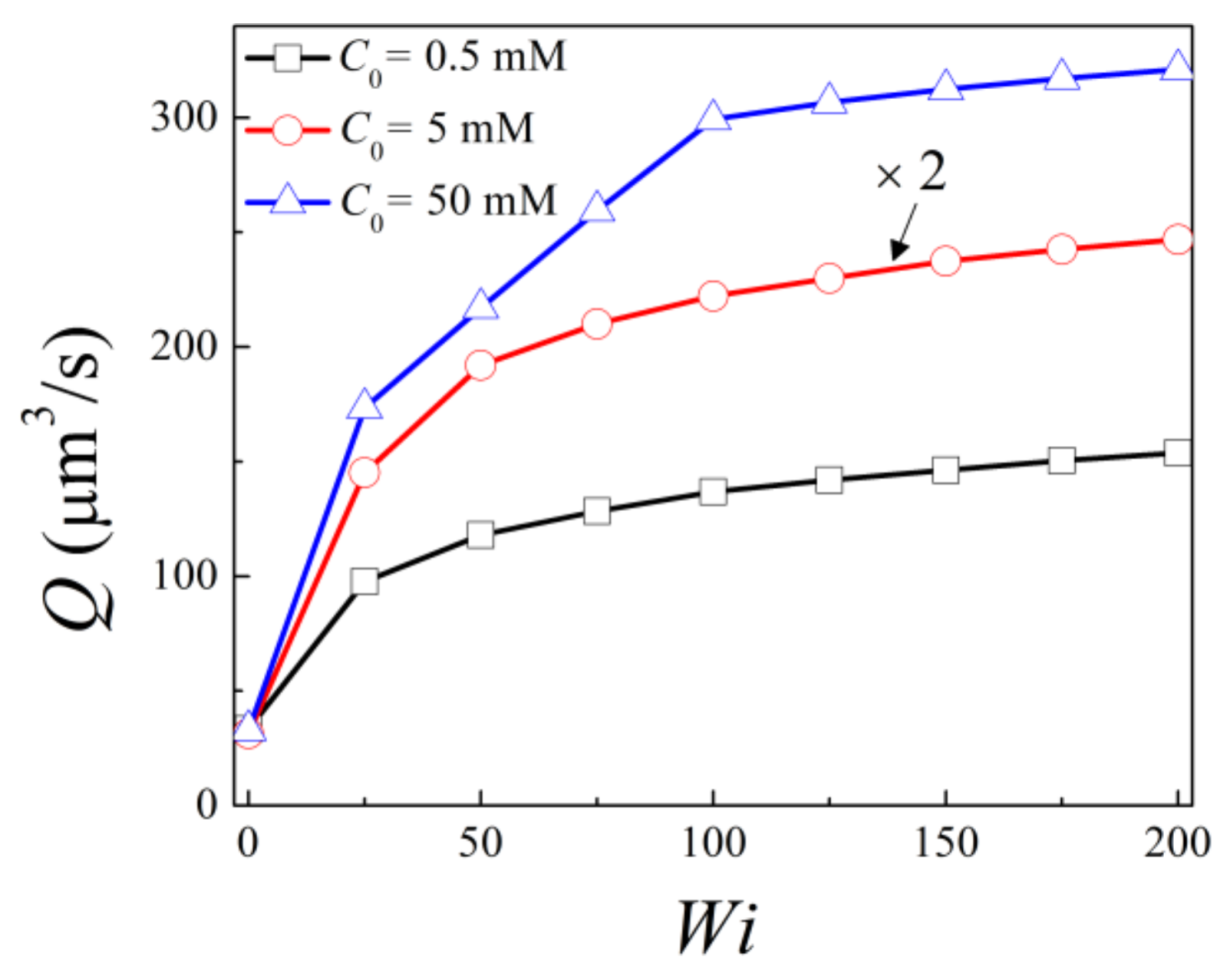
First of all, the volume flow rate across the channel is calculated at the middle of the channel (
) as
for bulk salt concentration
C0 = 0.5 mM, 5 mM, and 50 mM under different Weissenberg
Wi, as shown in
Figure 3. With the same Weissenberg number, the volume flow rate is lowest at C
0 = 0.5 mM, while it is the highest at C
0 = 5 mM. The former is because for low bulk salt concentration C
0 = 0.5 mM, the overall net charge density and thus the electric body force within the nanochannel is low. The highest flow rate at moderate bulk salt concentration C
0 = 5 mM is due to the fact that the EDLs are slightly overlapped, so the net ionic concentration within the nanochannel is higher compared to those for both C
0 = 0.5 mM and C
0 = 50 mM. Under the same bulk salt concentrations,
monotonously increases with
Wi within the investigated range, which is due to the shear thinning effect of viscoelastic fluid of the LPTT model. Besides this, the increase of flow rate is more obvious for
and becomes less apparent as
further increases. This indicates that the effect of
Wi on the shear viscosity becomes less apparent with increasing
Wi. At
Wi =200, the flow rates are 4.95, 7.89, and 9.74 times of that for Newtonian fluid at
C0 = 0.5 mM, 5 mM, and 50 mM, respectively. This indicates that the shear thinning effect is more obvious for the case with smaller EDL thickness.
The ionic conductance within the nanochannel is calculated as
In terms of dimensionless variables, the ionic conductance can be written as
It is obvious that the ionic conductance consists of convective, diffusive, and migrative components, which can be written as
Figure 4 shows the variation of the ionic conductance with the Weissenberg number for bulk salt concentrations of
C0 = 0.5 mM, 5 mM, and 50 mM, respectively. For
C0 = 0.5 mM and 5 mM, apparent increase of ionic conductance is seen for viscoelastic fluid compared to that of the Newtonian fluid, and the ionic conductance monotonously increase with
Wi. Similar to the trend of the flow rate, the increase becomes less obvious for higher
Wi. For 50 mM, ionic conductance slightly increases for viscoelastic fluid at
Wi = 50 compared to the Newtonian fluid, and remains almost constant as
Wi further increases. At
Wi = 200, the ionic conductance is 1.27, 1.20, and 1.03 times that for Newtonian fluid under bulk salt concentrations of
C0 = 0.5 mM, 5 mM, and 50 mM, respectively. Thus, the enhancement of ionic conductance is more obvious for low salt concentration, under which the EDLs are highly overlapped, and becomes less apparent as
C0 increases. When the bulk salt concentration is relatively high, the effect of viscoelasticity on the ionic conductance is negligible.
The variation of ionic conductance with
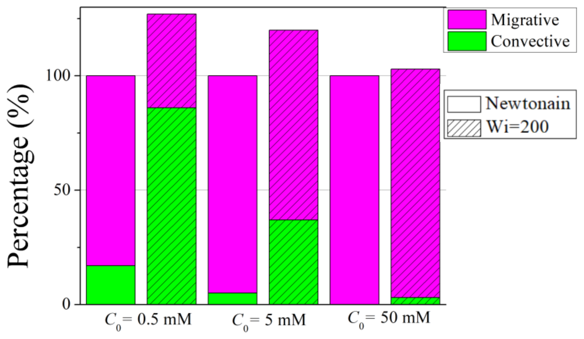
Wi for different bulk concentrations can be analyzed by the contributions of the convective, diffusive, and migrative components in Equation (20).
Figure 5 presents the percentage of the convective and migrative components for Newtonian fluid and viscoelastic fluid of
Wi = 200 at C
0 = 0.5 mM, 5 mM and 50 mM, respectively. The diffusive component is not shown due to the fact that for all cases, the percentage of diffusive conductance is less than 0.5%, and thus its contribution is negligible. Besides this, to better compare the results of the Newtonian fluid and the viscoelastic fluid, the percentage of viscoelastic is shown with respect to the Newtonian fluid under the same C
0. For viscoelastic of
Wi = 200, an apparent increase in the convective ionic conductance is observed compared to that of the Newtonian fluid, while an obvious decrease of migrative component is seen for viscoelastic fluid. The increase of the convective ionic conductance is due to shear thinning effect, as it is proportional to the mainstream velocity. The decrease of migrative ionic conductance stems from the change in the distributions of the electric potential and the ionic concentration under the presence of viscoelasticity. The increase of the convective component exceeds the decrease of the migrative component, resulting in an overall increase of the ionic conductance. Besides this, at low bulk salt concentration, the ratio of the convective component to the migrative component is relatively large, thus the increase of convective component for viscoelastic fluid contributes significantly to the increase of the total ionic conductance. As the bulk salt concentration increases, the contribution of the convective component becomes smaller, thus the increase of the total ionic conductance for viscoelastic fluid becomes less significant. In Newtonian fluid, the migrative component dominates for all three salt concentrations, while in viscoelastic fluid the convective component dominates when the EDLs are overlapped.
Figure 6 depicts the distribution of the dimensionless
along the centerline of the nanochannel for Newtonian fluid and viscoelastic fluid of
Wi = 200 for the case of overlapped EDLs (i.e., C
0 = 0.5 mM). Within the confined nanochannel, the value of
remains almost constant, while a sharp increase (decrease) occurs near the opening at the Cathode (Anode) side. This variation arises from the large change of net charge density within the solution in both reservoirs compared to the region near the nanochannel, due to the highly overlapped EDLs. Besides this, it is noticed that within the confined nanochannel, a decrease in the magnitude of
occurs for viscoelastic fluid compared to the Newtonian fluid. This decrease explains the decrease in the migrative ionic conductance, which is proportional to
. However, the effect of viscoelasticity on the electric potential distribution is not significant. This can be explained as following. As the surface charge density is assumed to be uniformly distributed at the nanochannel wall, the induced EOF velocity is almost parallel to the nanochannel surface. Under this condition, the ionic distribution and thus the electric potential is mainly determined by the surface charge density, and the increase of EOF velocity has negligible effect on the electric potential [
36].


