Article

Monitoring Structural Displacements on a Wall with Five-Constellation Precise Point Positioning: A Position-Constrained Method and the Performance Analyses

Department of Land Economics, National Chengchi University, Taipei City 116011, Taiwan
*
Author to whom correspondence should be addressed.
Remote Sens. 2023, 15(5), 1314; https://doi.org/10.3390/rs15051314
Submission received: 26 December 2022 / Revised: 20 February 2023 / Accepted: 24 February 2023 / Published: 27 February 2023
(This article belongs to the Special Issue Multi-GNSS: Methods, Challenges, and Applications)

Abstract

:
The global navigation satellite system (GNSS) precise point positioning (PPP) technique has been commonly applied to structural displacement monitoring. Considering the sheltering effect, GNSS receivers are regularly mounted on the top of a structure, but the structure is often not a rigid body; therefore, the receiver should also be mounted on the wall of the structure. Combining five constellations, GNSS can effectively reduce the sheltering effect. Therefore, this study attempts to apply the five-constellation PPP technique to monitor structural long-term displacements on the wall (SLDW) and structural vibrational displacements on the wall (SVDW) and then analyze their performance. Two novel methods are proposed in monitoring SVDW. Firstly, semi-generated measurements are designed to generate pseudo-environments with vibrations for the receiver. Therefore, additional instruments are not necessary to generate vibrations. Secondly, to further reduce the sheltering effect, a position-constrained PPP (PCPPP) model is developed. Formal performance analyses are presented in this study, and the results show that using the five-constellation PPP to monitor SLDW and SVDW in the horizontal direction is possible as long as the sheltering effect over the half sky of the receiver is not severe. In monitoring SVDW, the PCPPP model can perform better than the classical PPP model and be successful in the horizontal direction when the condition of elevation cutoff is given as high as 50°. For Asia-Pacific mid-low-latitude regions, the global positioning system (GPS) and BeiDou system (BDS) are important to maintain the availability of monitoring SVDW.

1. Introduction

Civil structures include bridges, buildings, tunnels, dams and so on [1]. Over the past decade, structures have been rapidly developed along with the global economy, but they may be deformed by long-term load, environmental changes and other effects. Structural deformation includes horizontal and vertical displacements occurring between different stories of a structure [2]. Studies indicate the cause of the displacements. For instance, ref. [3] described that earthquake can cause shear and torsion on a structure, resulting in structural displacements in the horizontal direction. Ref. [4] indicated wind force is a transverse loading that can cause structural displacements in the horizontal direction. Ref. [5] further found that loading increases with the height of a structure. Refs. [6,7] indicated that ground-borne vibrations, such as a train passing by, a neighbouring construction site and so on, cause slight and high-frequency vibrational behaviors in the vertical direction.
Structural long-term displacements and vibrational displacements are common behaviors in structural deformation [8]. Structural long-term displacement is caused by unavoidable aging and damage accumulation from the environments, and the displacement is a small permanent change [9]. A precise instrument, such as a global navigation satellite system (GNSS), is usually required to constantly inspect the displacement over a long period [10,11]. Structural vibrational displacement can be represented by levels of amplitudes and frequencies, and sometimes the frequencies can reach as high as 10 Hz [12].
Structural displacements are not separated on a structure uniformly, meaning that the sizes and directions of the displacements differ in any part of the structure. Ref. [11] found that the horizontal displacements on an entire dam are not uniformly separated. Ref. [13] also found that structural displacements on a historic building are not uniformly separated. These studies explain that a structure cannot be treated as a rigid body and that the overall wall and top of the structure should be considered when monitoring structural displacements.
Structural health monitoring (SHM) involves implementing a damage identification strategy for aerospace, civil structures and mechanical engineering infrastructure [8]. The GNSS precise positioning is a common means of SHM, including real-time kinematic (RTK) positioning and precise point positioning (PPP) techniques. The GNSS has many advantages, such as unnecessary visibility between monitoring points, weather independence and long-term monitoring support. Over the past years, many studies have discussed the use of GNSS precise positioning to monitor structural displacements. Ref. [14] used real-time kinematic (RTK) positioning to monitor the structural displacements of the Calgary Tower and found a low-frequency vibration of 0.36 Hz owing to the effect of wind force. Refs. [15,16,17] similarly monitored high-rise buildings with the GNSS precise positioning techniques and indicated that centimeter-level structural displacements can occur as a result of the effects of wind force and earthquakes. Refs. [18,19] monitored bridge deformation with RTK positioning, and they found structural displacements occur because of many factors, such as wind force, pedestrians, vehicles and temperature variations. To further understand the amplitudes and frequencies of vibrational displacements, studies regularly transform the displacements from the spatial domain to the spectral domain with mathematical tools, such as fast Fourier transformation (FFT), wavelet analysis and so on. Ref. [16] adopted FFT to inspect the vibrational displacements on a high-rise building. Ref. [18] compared FFT and wavelet analysis with a case of monitoring vibrational displacements on a bridge. The sheltering effect means that the GNSS signals are obstructed by structures, trees and so on, and the effect decreases the number of visible satellites. To avoid the sheltering effect, all of the above studies mount the receivers on the top of the structures.
The GNSS is composed of a global satellite system (GPS), Global’naya Navigatsionnaya Sputnikovaya Sistema (GLONASS), Galileo, BeiDou system (BDS), and quasi-zenith satellite system (QZSS). The more constellations are combined, the larger the number of visible satellites and the higher the positioning performance. Ref. [20] indicated that the positioning accuracy can be improved by combining constellations. Refs. [21,22] also found that combining constellations can improve the ambiguity resolution performance. Ref. [23] proved that combining constellations can effectively increase the availability of positioning in a dense urban area. As studies indicate that combining constellations can improve the accuracy and availability of positioning, ref. [24] attempted to evaluate the performance of monitoring structural displacements on a wall with a four-constellation (GPS/Galileo/BDS/QZSS) RTK positioning. The results show that centimeter-level accuracy can be achieved.
Structural displacement monitoring is important to people’s lives and property. Studies indicate that a structure is not a rigid body. If the condition is not negligible, the structural displacements must be overall considered, including the areas of the top, wall and so on. The PPP technique is widely used in SHM because it can be implemented with one station and achieve centimeter-level positioning accuracy. When implementing the PPP technique in SHM, people regularly mount the receiver on the top of a structure considering a sufficient number of visible satellites, but the structural displacements monitored become subject to the area of the top. Combining the five constellations can effectively increase the number of visible satellites, so it may enable monitoring structural displacements on the wall. This study attempts to adopt the PPP technique combining five constellations (GPS/Galileo/GLONASS/BDS/QZSS) to monitor structural long-term displacements on the wall (SLDW) and structural vibrational displacements on the wall (SVDW). In the analyses, this study collects GNSS data from an open-sky situation and uses levels of masking conditions, including azimuth and elevation cutoffs, to present situations where the receiver can only track satellites over half the sky at most. The performance of monitoring SLDW and SVDW can then be formally analysed. For monitoring SVDW, this study designs semi-generated measurements to produce a pseudo-environment with vibrations for the receiver; to further reduce the sheltering effect, a positioning-constrained PPP (PCPPP) model is proposed.

2. Methodology

In this section, a classical PPP model, the PCPPP model and Kalman filter are firstly introduced. A linear velocity estimation for monitoring SLDW and the semi-generated GNSS measurements are then described.

2.1. Classical PPP Model

The classical PPP model adopts between-satellite single-differenced (BSSD) measurements to eliminate receiver-related systematic errors, including the clock errors, code biases and phase biases. The processing strategies for other systematic errors are given in Table 1.
When two satellites are tracked in a constellation, the BSSD measurements can be expressed as follows [27]:
P r , j s 1 s 2 = ρ r s 1 s 2 + m ( E r s 1 s 2 ) Z T D + μ j I r s 1 s 2 + e r , j s 1 s 2
Φ r , j s 1 s 2 = ρ r s 1 s 2 + m ( E r s 1 s 2 ) Z T D μ j I r s 1 s 2 + λ j N ˜ r , j s 1 s 2 + ε r , j s 1 s 2
where the subscript r identifies the receiver and j refers to signal identifier. Φ r , j s 1 s 2 and P r , j s 1 s 2 denote the phase and code BSSD measurements, respectively; ρ r s 1 s 2 is the BSSD geometric distance. μ j = ( f 1 / f j ) 2 identifies the ionosphere coefficient, where f j means the frequencies and f 1 refers to the first frequency of each constellation. m ( ) describes the Neill mapping function [29], E r s 1 s 2 means the difference of elevations for the two satellites s1 and s2, the parameter ZTD refers to the zenith troposphere delay, λ j refers to the wavelength and e r , j s 1 s 2 is the measurement noise plus multipath effects. N ˜ r , j s 1 s 2 is a lumped parameter, which can be read as:
N ˜ r , j s 1 s 2 = N r , j s 1 N r , j s 2 + δ r , j s 1 δ r , j s 2 + Δ r , j s 1 Δ r , j s 2
where N r , j s 1 and N r , j s 2 are the integer ambiguities, δ r , j s 1 and δ r , j s 2 refer to the satellite phase biases. The symbols Δ r , j s 1 and Δ r , j s 2 mean the inter-channel bias of GLONASS.
When the five constellations are received by the receiver, the linearized observation equations can be read as follows:
E ( L ) = A a + B b + C c + M Z T D ,   D ( L ) = Q L
where E ( ) and D ( ) are expectation and dispersion operators, respectively. The vector L is composed of BSSD measurements minus the computed values, which can be expressed as follows:
L = [ P r , j G 1 G s G P r , j E 1 E s E P r , j R 1 R s R P r , j B 1 B s B P r , j J 1 J s J Φ r , j G 1 G s G Φ r , j E 1 E s E Φ r , j R 1 R s R Φ r , j B 1 B s B Φ r , j J 1 J s J ] 4 ( m G + m E + m R + m B + m J - 5 ) × 1 T
where the subscripts G, E, R, B, J represent the constellations GPS, Galileo, GLONASS, BDS and QZSS, respectively. s G = 2 , , m G , s E = 2 , , m E , s R = 2 , , m R , s B = 2 , , m B , s J = 2 , , m J , in which m * refers to the number of visible satellites for each constellation ( = G, E, R, B, J) and 1 * refers to the respective pivot satellites. The subscripts j G = L 1 , L 2 , j E = E 1 , E 5 a , j B = B 1 I , B 2 b , j R = G 1 , G 2 , j J = L 1 , L 2 . The vector a comprises the lumped parameters and is expressed as follows:
a = [ N ˜ r , j G 1 G s G N ˜ r , j E 1 E s E N ˜ r , j R 1 R s R N ˜ r , j B 1 B s B N ˜ r , j J 1 J s J ] 2 ( m G + m E + m R + m B + m J 5 ) × 1 T
The vector b comprises the parameters for position increments in the Earth-Centred Earth-Fixed (ECEF) frame and is expressed as follows:
b = [ dX dY dZ ] T
The vector c is composed of parameters for BSSD ionospheric delays and is expressed as follows:
c = [ I r 1 G s G I r 1 E s E I r 1 R s R I r 1 B s B I r 1 J s J ] ( m G + m E + m R + m B + m J - 5 ) T
The design matrices A, B, C and M correspond to the parameter vectors a, b, c and ZTD, respectively. Q L refers to the variance–covariance (VC) matrix for the vector L.

2.2. PCPPP Model

The PCPPP model is proposed to improve the performance of monitoring SVDW with the classical PPP model. Different from the classical PPP model, the PCPPP model is given with additional positional pseudo-observations of a wall point (i.e., location of the receiver on the wall). With the observations, the PCPPP model can decrease the uncertainty for the parameters of position increments. The linearized observation equation of the PCPPP model can be expressed as follows:
{ E ( L ) = A a + B b + C c + M Z T D ,   D ( L ) = Q L E ( b c ) = I b ,   D ( b c ) = σ b c 2 I
where I is a 3 × 3 identity matrix and b c refers to the vector comprising the positional pseudo-observations. Since b c is given before a vibration occurs, one has to note that the wall point cannot be dislocated during suffering from the vibration. The standard deviation σ b c is a given value. If σ b c is given too optimistically or pessimistically, the positioning increments will be inappropriately estimated. In this study, in the case of combining the five-constellations measurements, it is denoted as five-constellation PPP and five-constellation PCPPP when the classical PPP and PCPPP models are adopted, respectively. It is denoted as GPS PPP when only GPS measurements are used for the classical PPP model.

2.3. Kalman Filter

The Kalman filter is used to process the unknown parameters of the PPP models. The PPP models can be rewritten as follows:
E ( G k ) = F k X k ,   D ( G k ) = Q G k
where G k refers to the observation vector at epoch k. The vector G k = L k and G k = [ L k b c ] T for the classical PPP and PCPPP models, respectively. F k identifies the design matrix. For the classical PPP and PCPPP models, the respective design matrices are shown in (11) and (12),
F k = [ A k 0 B k C k 0 M k ]
F k = [ A k 0 B k C k M k 0 I ]
and the unknown parameter vector is X k expressed as (13).
X k = [ a k b k c k Z T D k ] T
The Kalman filter processes the unknown parameters with prediction and updating [30]. For the prediction, the Kalman filter predicts the result of the unknown parameters at the next epoch without real measurements. It can be expressed as follows:
X ^ k = Φ k - 1 X ^ k - 1 + W k
where Φ k - 1 refers to a transition matrix composed of an identity matrix, X ^ k means the vector of the predicted parameters and W k is a vector is composed of the system process noises which are normally distributed with a zero mean. According to the error propagation theorem, the VC matrix of X ^ k can be read as follows:
Q X ^ k = Φ k - 1 Q X ^ k - 1 Φ k - 1 T + Q W k
where Q W k refers to the VC matrix of W k . The matrix Q W k is a diagonal matrix, where the elements for the lumped parameters are given with zero when no cycle slip occurs, and the elements for the parameter of the position increments are given with zero when the receiver is treated to be stationary (i.e., a static mode) and with 10 2   m 2 in case the receiver suffers from effects of vibrations (i.e., a kinematic mode). Both the parameter of the ionospheric delays and ZTD generally change slowly in time, and their elements in Q W k can be given with empirical values of 0.03 2   m / s 2 and 0.0003 2   m / s 2 , respectively. The related references can be found in [26,31].
For updating, the Kalman filter uses real measurements at the current epoch to refine the predicted unknown parameters, which can be expressed as follows:
X ^ k = X ^ k K k ( F k X ^ k G k )
Q X ^ k = ( Q X ^ k K k F k Q X ^ k )
where K k is the Kalman gain matrix. The VC matrix of the updated unknown parameters X ^ k is denoted as Q X ^ k , which can be expressed as follows:
Q X ^ k = [ Q a ^ k Q b ^ k symmetry symmetry Q c ^ k σ ZTD k 2 ]
where Q a ^ k , Q b ^ k and Q c ^ k refer to the respective VC matrices for the unknown parameters.
The unknown parameters of the position increments are under the ECEF frame. Then, we can transform them from the ECEF frame to a local geodetic system (N, E and U). The origin of the system is the point of observation (i.e., the observation station). At epoch k, the position increments under the local geodetic system are denoted as, d N k , d E k , and d U k , and the standard deviation are denoted as σ d N k , σ d E k and σ d U k . The detailed transformation theory can be found in [32].

2.4. Velocity Estimation for Structural Long-Term Displacements

Structural long-term displacements can be represented in various behaviors. For instance, ref. [11] discussed the behaviors with linear, cubic and cubic Hermite methods. Ref. [33] put the behaviors in a rigorous model. Since our study focuses on the performance of using the PPP technique in monitoring SLDW, the behavior is presented by a linear function of time series. It is also a basic means to represent structural long-term displacements. In a long period, the linear function can be expressed as follows:
l t m = l t 0 + V ( t m t 0 ) + b 0
where t 0 refers to the first epoch and t m is the m-th epoch. Vectors l t 0 and l t m comprise the position of the receiver at t 0 and t m , respectively. V and b 0 mean the velocity (or slope) and intercept for the structural long-term displacement, respectively. After the positions of the receiver in a long period are collected, the estimated velocity and intercept, denoted as V ^ and b ^ 0 , can be calculated by the least-squares estimation. However, the PPP technique is based on the ECEF frame, of which origin is at the mass centre of the Earth. Therefore, the long-term velocity caused by crustal deformation is reflected on the estimated V ^ . Considering the problem, a well-developed model for the crustal deformation is adopted in this study. In concept, the model is constructed with a semi-kinematic reference frame and is realised by an operation of continuous operating reference station (CORS) network. The development of the model can be referenced to [34]. After eliminating the velocity produced by the model, the corrected velocity of the structural long-term displacement can be obtained as follows:
V ˜ = V ˜ V crustal
where V ˜ is the corrected velocity, and V crustal refers to the velocity from the model.

2.5. Semi-Generated GNSS Measurements

The semi-generated GNSS measurements are used to make pseudo-environments with vibrations for the receiver. Therefore, additional instruments are no longer needed to really produce vibrations. Moreover, any level of vibrational amplitudes and frequencies can be generated with this method. Firstly, a sinusoidal with time series is adopted to generate vibrational displacements. The generated vibrational displacements in the local geodetic system can be expressed as:
D i , t = A i sin ( 2 π F t )
where the subscript i refers to the directions in the local geodetic system (i.e., i = N, E, U) and D i , t is the generated vibrational displacements for the receiver at epoch t. A is the vibrational amplitude and F is the vibrational frequency. The displacements in Equation (21) are then transformed into ranges in the ECEF frame as follows:
Δ ρ r , t s 1 = p e t s 1 p e r , t p e t s 1 p e r , t S 1 [ D N , t D E , t D U , t ]
S = [ - sin L 0 cos L 0 0 - sin B 0 cos L 0 - sin B 0 sin L 0 cos B 0 cos B 0 cos L 0 cos B 0 sin L 0 sin B 0 ]
where B 0 and L 0 refer to the geographic latitude and longitude of the receiver, respectively. Δ ρ r , t s 1 means the range from the satellite s1 and receiver r. p e t s 1 and p e r , t identify the position vectors of the satellite and receiver in the ECEF frame, respectively. After the ranges are computed for all satellites, they are added on the corresponding raw GNSS measurements to change the geometry distances. The new GNSS measurements are called semi-generated measurements, as shown in Figure 1.

3. Monitoring SLDW

The formal performance of monitoring SLDW is presented in this section. Test data are collected from a Trimble Net R9 receiver equipped at one permanent station on the top of a 16-storey structure at National Chengchi University (NCCU), Taiwan, as shown in Figure 2. The station is in an open-sky situation and located in the Asia-Pacific mid-low-latitude region (latitude: 25°3′, longitude: 121°30′). The data include five-constellation dual-frequency measurements, and one-day measurement is collected every week from 1 August 2019 to 31 July 2020. Therefore, 52-day measurements are used in this analysis.
The observation interval is 30 s (i.e., 2880 epochs per day). This study gives a masking condition, in which an azimuth cutoff, from 90° to 270°, is used to present a situation where the station is mounted on the wall. Under this masking condition, the number of visible satellites is significantly decreased because all geostationary satellites on the equator are removed. In addition to the masking caused by the wall, this study considers other possible obstructions over the half sky of the receiver, such as the neighbouring structures. Therefore, the masking condition is further given with seven elevation cutoffs, which are 15°, 30°, 35°, 40°, 45°, 50° and 55°, as shown in Figure 3, and the respective sky plots are shown in Figure 4. The two figures reveal that if the receiver is more down to the bottom of the structure, then more satellites are obstructed.

3.1. Velocity of Station NCCU

The five-constellation PPP is used to computed the daily solutions for the 52 days. The daily solution means the GNSS measurements in a whole day are processed with the Kalman filter in the static mode. The VC matrix of the measurements Q L is given according to an elevation-dependent function, which is expressed as follows:
σ = ( 1 sin ( E l e ) ) σ 0
where Ele refers to the satellite elevation angle. σ 0 means the measurement noise in the zenith direction, which is 0.003 m and 0.3 m for the phase and code measurements, respectively. The 52 daily solutions are then used to estimate the velocity by Equations (19) and (20). The estimated velocity in an open-sky situation is denoted as V ˜ Ref . and shown in Figure 5. Owing to the open-sky situation, the number of visible satellites is sufficient and the velocity can be estimated with confidence. Therefore, V ˜ Ref . is adopted to be a reference value in the following performance analysis.
The standard deviations of each daily solution are obtained at epoch k = 2880, and they are denoted as σ d N 2880 , σ d E 2880 and σ d U 2880 in the local geodetic system. The standard deviations of the 52 daily solutions are illustrated in Figure 6. The result indicates that the standard deviations are stable and that no secular variation occurs either in an open-sky or a severely obstructed situation. Therefore, in this analysis, we roughly regard the standard deviations of the first daily solution, denoted as σ d N day , σ d E day and σ d U day , to represent those of the 52 daily solutions. For the masking conditions, Table 2 lists the standard deviations of the first daily solution and the average of the number of visible satellites for the 52 days. The table indicates that the standard deviations and the average obviously worsen when the elevation cutoffs decreases.

3.2. Performance Analysis

The five-constellation PPP and GPS PPP are used to estimate the velocities at the masking conditions, and the root-mean-squares (RMS) values are listed in Table 3.
The estimated velocities should be similar with V ˜ Ref . because the same station is used. This study then uses the Student’s t-test to verify whether the estimated velocities are similar with V ˜ Ref . in statistic. The difference of the estimated velocities and V ˜ Ref . is expressed as follows:
dv = V ˜ Obstruction   V ˜ Ref . = ( V ^ Obstruction V crust ) ( V ^ Ref . V crust )                 = V ^ Obstruction V ^ Ref .
The standard deviation is given as:
σ dv = σ V ˜ Obstruction 2 + σ V ˜ Ref . 2
where V ˜ Obstruction and σ V ˜ Obstruction refer to the estimated velocity and the related standard deviation at one masking condition. The Student’s t-test and the test value are expressed as follows:
{ H 0 : dv = 0   H 1 : dv 0
Test   value = dv σ dv
If the null hypothesis H 0 is accepted, V ˜ Obstruction and V ˜ Ref . have no significant difference, whereas the alternative hypothesis H 1 is accepted when a significant difference exists. In the Student’s t-test, the significant level is given with 95% and the degree of freedom is 51. Therefore, the threshold of the test value is 2.0076. Once the computed test value by Equation (28) is smaller than the threshold, the alternative hypothesis H 0 is accepted.
In Figure 7 and Figure 8, the GPS PPP and five-constellation PPP are used, respectively, to compute the test values at the masking conditions. In the two figures, we focus on the results in the horizontal (i.e., E and N directions) and vertical (i.e., U direction) directions. In the case of using the GPS PPP, Figure 7 shows that the computed test value is smaller than the threshold when the elevation cutoff is lower than 30° in the horizontal direction. By contrast, no computed test value is smaller than the threshold in the vertical direction. In the case of using the five-constellation PPP, Figure 8 shows that, in the horizontal direction, the computed test value can be smaller than the threshold when the elevation cutoff reaches as high as 55°. In the vertical direction, the computed test value is smaller than the threshold when the elevation cutoff is only at 15°. These results explain that the five-constellation PPP can perform better than the GPS PPP. However, the five-constellation PPP still performs poorly in the vertical direction when the elevation cutoff is high.
From another aspect, Figure 7 and Figure 8 show that the computed test values start to become close to or larger than the threshold when σ d N day , σ d E day or σ d U day are larger than 0.4 cm. This result implies that a criterion, in which the standard deviation of the daily solution should not be larger than 0.4 cm, can be made for users to judge whether the wall point is certain in monitoring SLDW. When the criterion holds true, for five-constellation PPP, Figure 8 shows the computed test values in the horizontal and vertical directions can be smaller than the threshold when the elevation cutoffs are lower than 45°and 15°, respectively. According to Table 3, the RMS values corresponding to the two elevation cutoffs can be 0.8 cm in the U direction and within 0.5 and 0.3 cm in the E and N directions, respectively.
As expressed in Equation (20), a well-developed model for crustal deformation is adopted in this analysis. The uncertainties of the model affect the results of monitoring SLDW. Therefore, the accuracy of the model must be noticed in practice. The uncertainties do not affect the results of the performance analysis because the velocities of crustal deformation are eliminated by Equation (25).

4. Monitoring SVDW

In this section, we analyse the performance of monitoring SVDW with the classical PPP model. We then evaluate the performance improvement of the PCPPP model by comparing the classical PPP and PCPPP models. Similar to the previous section, the test data are collected from the receiver at station NCCU, and levels of masking conditions are used to analyse the performance. To present an environment with vibration, the semi-generated measurements are adopted. The observation sampling rate is 10 Hz, and the observation period is 00:00–22:55 (GPS time), 12 January 2022. The reference coordinate of the station is the daily solution on this date with the five-constellation PPP. Throughout the analysis, the initial epoch of the Kalman filter is set at 00:00, and the kinematic mode is adopted, considering the vibrations.

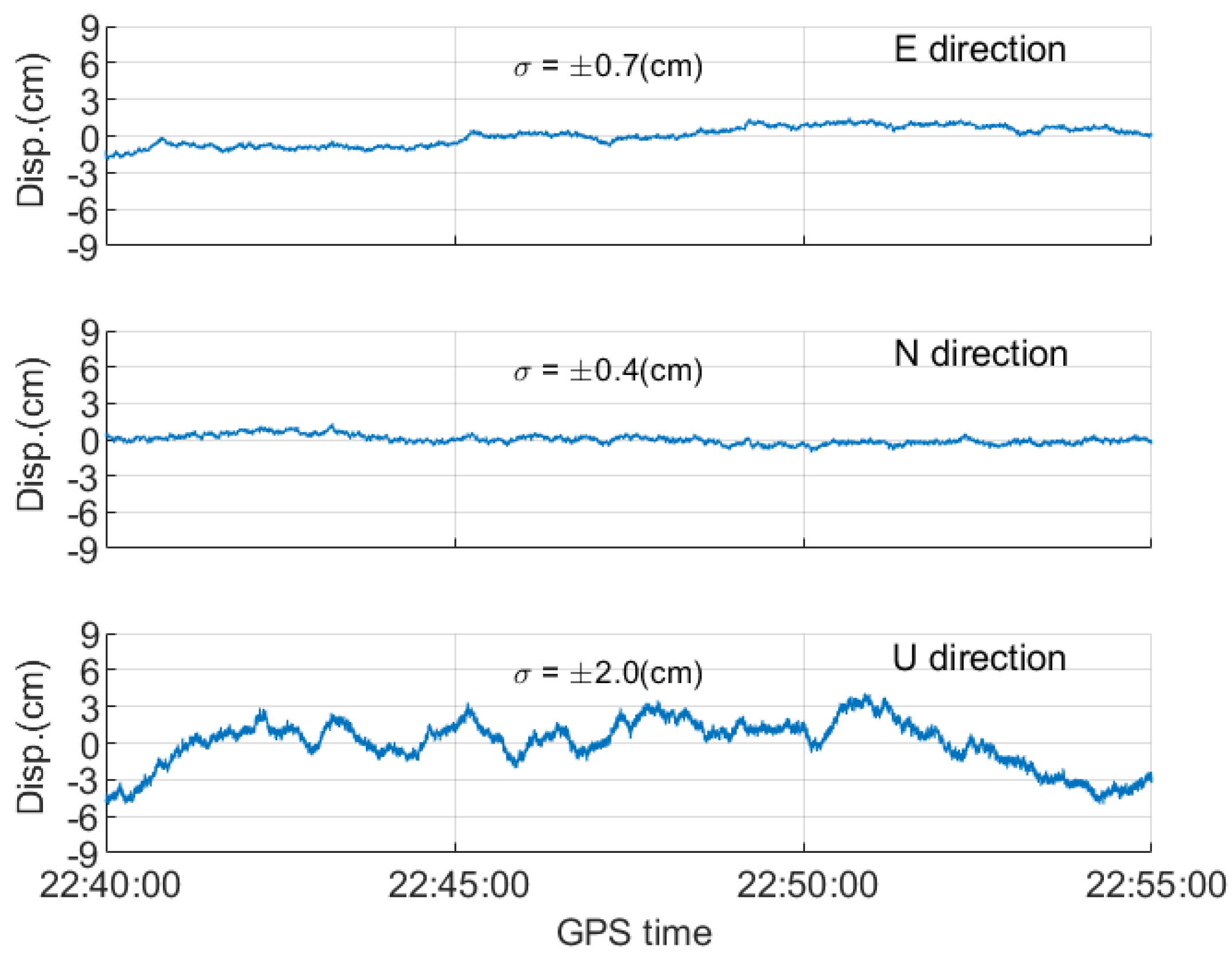
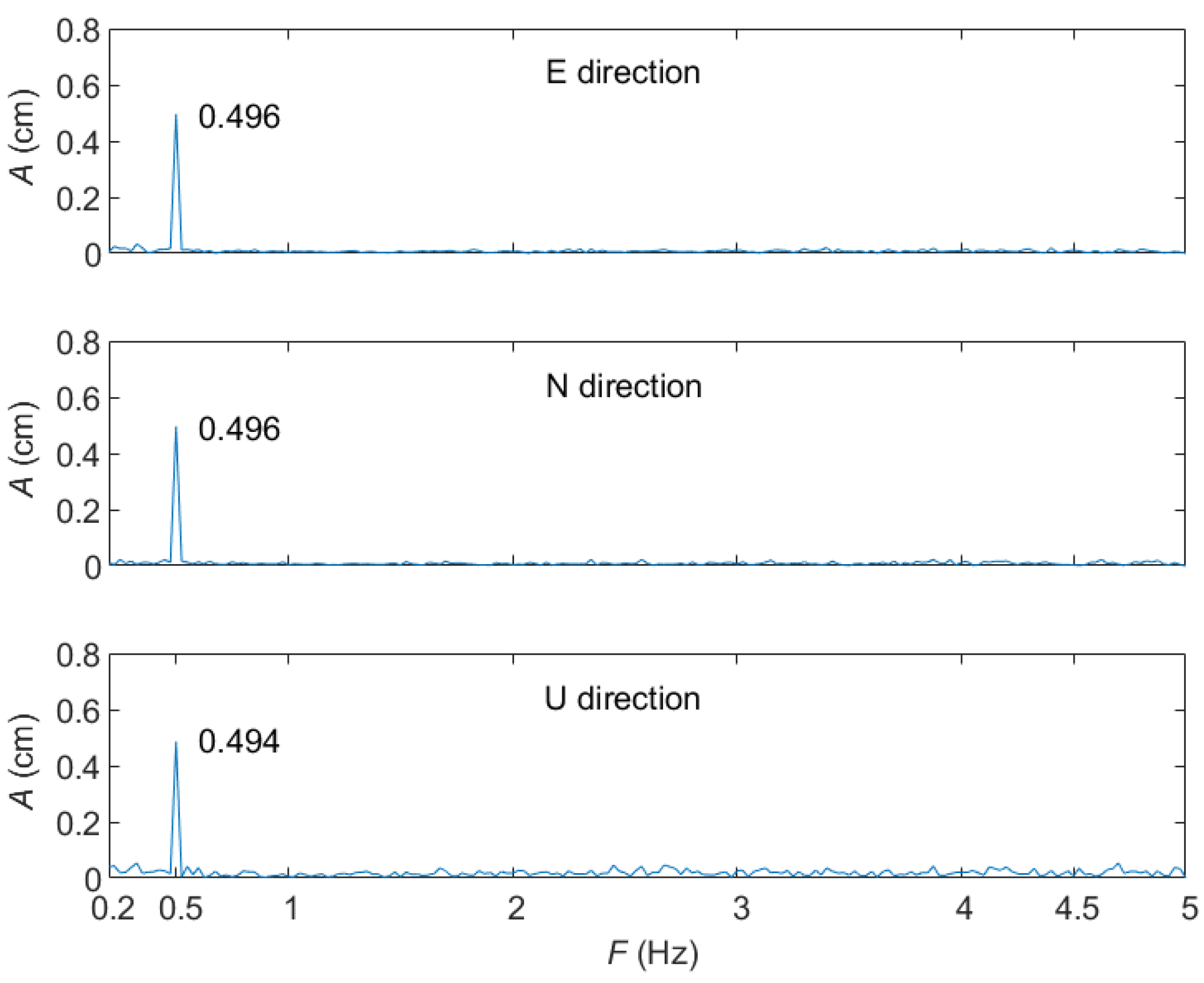
4.1. Vibrational Displacements of Station NCCU

The station is stationary, so the inconsistency between the positioning results and the reference coordinate are deemed the vibrational displacements. Considering the PPP technique needs at least several hours to produce confident results, a test session of over the last 15 min (i.e., 22:40–22:55) is adopted here. In the test session, the total number of visible satellites for the five constellations is 35. Figure 9 shows the vibrational displacements with the raw GNSS measurements. The five-constellation PPP is adopted during the process. FFT is then used to produce the spectrum of the vibrational displacements, as shown in Figure 10. In the FFT spectrum, if a vibrational behavior exists and is obvious enough to be detected, a significant peak occurs in the spectrum. However, no significant peak can be found in the FFT spectrum, which aligns with the fact that the station is stationary. Although no peak can be found, large amplitudes are noted at the vibrational frequencies lower than 0.2 Hz. The large amplitudes are mainly caused by the GNSS signal multipath [35].

4.2. Verifying the Semi-Generated GNSS Measurements

In the analysis, this study uses the semi-generated measurements for the receiver to produce vibrational behaviors and the FFT to verify whether the vibrational amplitudes and frequencies can be detected as large as given in the semi-generated measurements. According to general vibrational behaviors of high-rise buildings and bridges, i.e., they are affected by the surrounding environments, such as wind force, pedestrians, trains and so on, the amplitudes can be as small as values less than 1 cm, and the vibrational frequencies caused by wind force could reach as low as 0.2 Hz, and the train-induced vibrations are at least 5 Hz [7,16,18]. Therefore, the analysis takes these values into account and uses Equation (21) to derive a high-frequency and low-frequency vibrational behaviors on the N, E and U directions. The amplitude is similarly given with 0.5 cm (i.e., <1 cm) for the two vibrational behaviors. The low-frequency vibrational behavior is given with 0.5 Hz (i.e., approximate to 0.2 Hz) in the frequency. According to the Nyquist theorem [36], the effective sampling frequency cannot be higher than half the observation sampling rate; therefore, for the high-frequency vibrational behavior, the vibrational frequency is roughly given with 4.5 Hz (i.e., ≈10 Hz/2). The test session is from 22:46:30 to 22:47:10 (40 s), during which the total number of visible satellites for the five constellations is 35.
Since this study attempts to compare the performance of the two PPP models in monitoring SVDW, a simple case, whose amplitude and vibrational frequencies are time-invariant in the test period, is assumed. In order to clearly distinguish the performance in the horizontal and vertical directions, the given values on the N, E and U directions are the same. The vibrational displacements for the two behaviors are computed with the five-constellation PPP, as shown in Figure 11 and Figure 12.
Subsequently, this study uses the FFT to verify whether the detected vibrational amplitudes and frequencies are as large as given in the semi-generated measurements. To alleviate the multipath effects, a high-pass filter with the cutoff frequency = 0.2 Hz is used. Figure 13 and Figure 14 show the detected vibrational amplitude and frequency in the FFT spectrum for the low- and high-frequency vibrational behaviors, respectively. Figure 13 shows that a peak approximating to 0.5 cm amplitude occurs at 0.5 Hz, which is as large as given in the semi-generated measurements. In Figure 14, a peak approximating to 0.5 cm occurs at 4.5 Hz. The above results explain that using the semi-generated measurements actually can reflect the vibrational behaviors on the positioning results.

4.3. Performance Analysis with the Classical PPP and PCPPP Models

Two issues are discussed in this section. Firstly, the performance with the classical PPP model is evaluated. Next, the performance with the PCPPP model is compared with that with the classical PPP model to evaluate the improvement.
In the first issue, the classical PPP model is adopted and three masking conditions are considered, and the elevation cutoffs of which are 15°, 30° and 50°. Their azimuth cutoffs have the same range, from 90° to 270°. The test session is from 22:46:30 to 22:47:10 (40 s), which is the same as that in the previous section. In the test session, the number of visible satellites for each constellation is m G = 5, m E = 3, m C = 2, m R = 2 and m J = 1 at elevation cutoff = 15°; m G = 3, m E = 2, m C = 2, m R = 2 and m J = 0 at elevation cutoff = 30°; m G = 1, m E = 2, m C = 2, m R = 1 and m J = 0 at elevation cutoff = 50°.
The FFT spectrums of the vibrational behaviors are made according to the previous section. In the FFT spectrum, if only one obvious peak can be found at the given vibrational frequency, it is regarded as an available peak. Figure 15 and Figure 16 show the sizes of the available peaks for the GPS PPP and five-constellation PPP, respectively. In the two figures, if no available peak occurs, they are denoted as N/A. The green and blue bars refer to the high-frequency and low-frequency vibrational behaviors, respectively. When the inconsistency for the size of the available peak and the given vibrational amplitude is within 0.1 cm, the related vibrational behavior is deemed detectable.
The performance analyses are conducted by comparing Figure 15 and Figure 16. At elevation cutoff 15°, the low-frequency vibrational behavior is undetectable in the vertical direction when the GPS PPP is used; on the contrary, it is detectable when the five-constellation PPP is used. At elevation cutoff 50°, the GPS PPP is unavailable because of insufficient number of visible satellites, whereas the high-frequency vibrational behavior is detectable in the horizontal direction when the five-constellation PPP is used. The above comparisons indicate that the five-constellation PPP can perform better than the GPS PPP in monitoring SVDW. However, the five-constellation PPP still performs poorly for low-frequency vibrational behaviors and in the vertical direction when the elevation cutoff is higher than 15°. The poor performance in monitoring low-frequency vibrational behaviors mainly results from the effects of GNSS signal multipath, as mentioned in [36].
In the second issue, the PCPPP model is used to improve the performance of monitoring the vibrational behaviors. In Equation (9), the positional pseudo-observations b c are given with the difference of the reference and the initial coordinates in the Kalman filter. Figure 16, Figure 17 and Figure 18 show the sizes of the available peaks with the five-constellation PCPPP with σ b c = ± 1 , σ b c = ± 9 and σ b c = ± 15 cm, respectively. Compared with Figure 16, Figure 17 indicates that the low-frequency vibrational behavior becomes detectable in the horizontal direction after using the PCPPP model at cutoff 30°. However, at cutoff 15°, the high-frequency and low-frequency vibrational behaviors in the vertical direction become undetectable. At cutoff 50°, the high-frequency vibrational behavior in the horizontal direction also becomes undetectable. The reason is that the condition σ b c = ± 1 cm is given optimistically.
In the comparison of Figure 16 and Figure 18, at cutoff 30° and 50°, the low-frequency vibrational behavior in the horizontal direction becomes detectable. This finding implies that when the condition σ b c = ± 9 cm is adopted, using the PCPP model can improve the performance of monitoring the low-frequency vibrational behavior in the horizontal direction. Next, the comparison of Figure 16 and Figure 19 shows no obvious improvement after using the PCPPP model. The explanation is that the condition σ b c = ± 15 cm is given pessimistically. According to the above comparisons, using the PCPPP model can further improve the performance of monitoring SVDW, particularly for low-frequency vibrational behaviors and in the horizontal direction. However, the standard deviation σ b c must be given appropriately. According to the test results, the condition σ b c = ± 9 cm can be a referenceable value in practice.

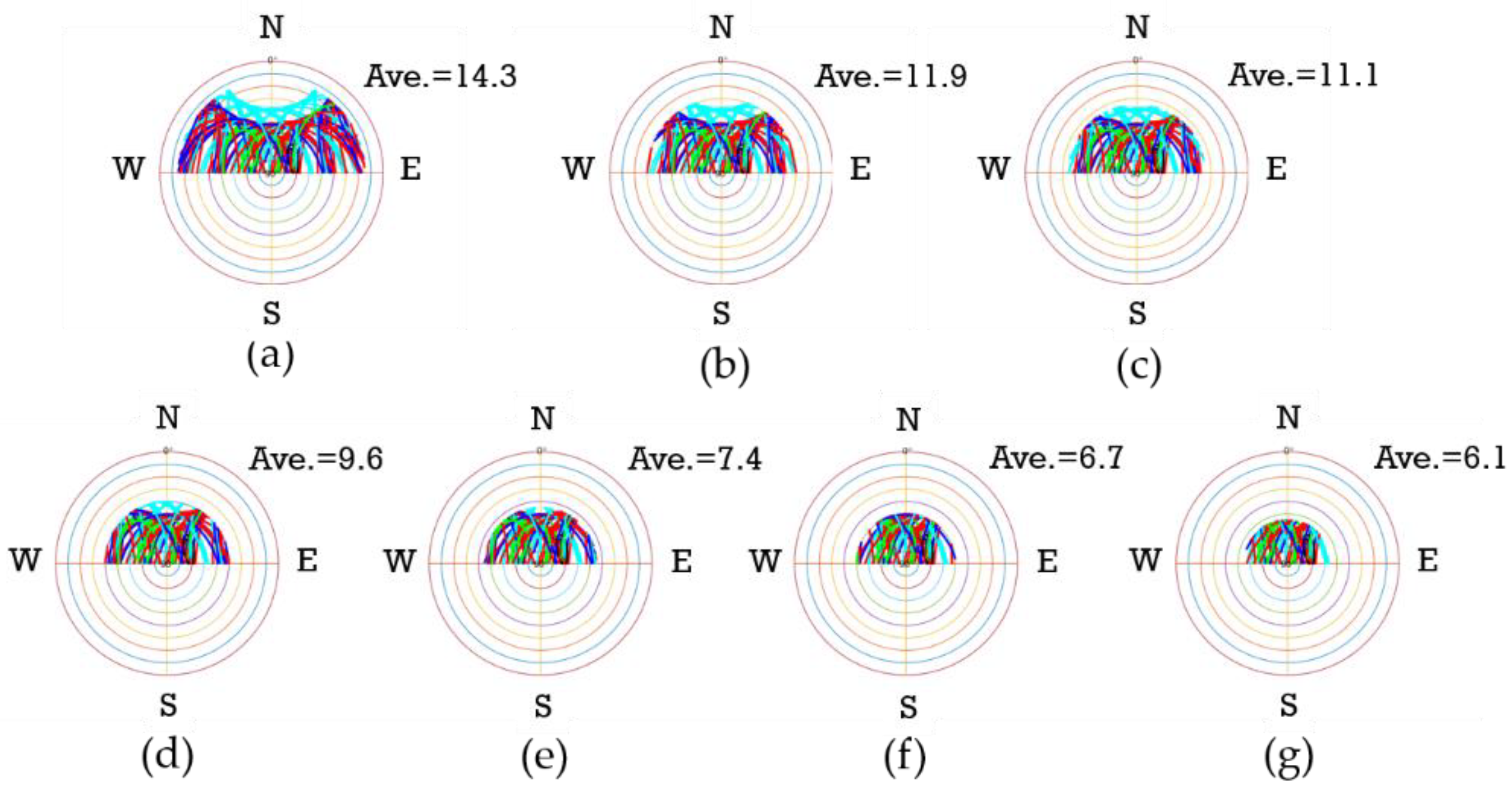
4.4. Availability Analysis for the Asia-Pacific Mid-Low-Latitude Regions

Availability here refers to whether the number of visible satellites is enough to estimate the unknown parameters in the PPP models when monitoring SVDW. Every constellation has its own orbit characteristic, resulting in different satellite separations worldwide. For instance, the QZSS satellites can be observed with very high elevations (at least ≥60°) over Japan. The geostationary satellites move on the equator. The GLONASS has a dense satellite separation in high-latitude regions. Therefore, the availability changes with different regions. In this analysis, we use the station NCCU, located in the Asia-Pacific mid-low-latitude region, to analyse the availability over the region.
The lumped parameters in the two PPP models are treated as time-invariant parameters, so the number of the unknown parameters of the two models in the kinematic mode can be expressed as follows:
u t m = 3 t m + 2 ( M ˜ N * ) + t m ( M ˜ N * ) + t m
With the assumption that no cycle slip occurs and that the number of visible satellites is unchanged from t 0 to t m . u t m refers to the total number of parameters from t 0 to t m . The total number of visible satellites is described as M ˜ ( M ˜ = m G + m E + m R + m B + m J ). Owing to the use of BSSD measurements, if the number of visible satellites m * for one constellation is smaller than 2, then the constellation is abandoned in the PPP models. It can be expressed as:
if   m * <   2 ,   then   m * = 0  
The symbol N * means the number of existing constellations. The existing constellation means its m * has to be ≥2. The total number of measurements from t 0 to t m comprises dual-frequency codes and phases, which is expressed as:
o b s t m = 4 t m ( M ˜ N * )
The redundancy number is the difference of o b s t m and u t m . If the PPP models are solvable, then the redundancy number ≥0. When it holds true, the total number M ˜ can be expressed as following the inequality
M ˜ ( 3 t m N * + 4 t m 2 N * 3 t m 2 ) ceil
where ( ) ceil refers to a function of finding the smallest integer that is greater than or equal to the input value . As the number m * for an existing constellation has to be ≥2, the total number M ˜ should be larger and equal to 2 N * . If not, the number M ˜ is 2 × N * , expressed as follows:
if M ˜ < 2 N * ,   then M ˜ = 2 N *  
After the PPP models are processed with one, two and three epochs, the smallest number of M ˜ can be obtained with Equations (32) and (33). Table 4 lists the results, showing that when more than two epochs are processed, the PPP models are solvable with the condition m * 2 when multiple constellations are processed. According to the condition and Table 2, only GPS/BDS PPP can effectively maintain the availability when the elevation cutoff is as high as 45° because only m ¯ G and m ¯ B are ≥2 when the elevation cutoff is at 45°. Therefore, it can be found that GPS and BDS are important to maintain the availability of monitoring SVDW in the Asia-Pacific mid-low-latitude regions.

5. Discussion

For monitoring structures, GNSS receivers are mounted on the tops of structures in current studies [14,15,16,17,18,19]. Compared with these studies, this study presents the formal performance of monitoring structural displacements on a wall and indicates that monitoring SLDW and SVDW with the five-constellation PPP is possible for occasions in which the sheltering effect over the half sky of the receivers is not severe. The occasions generally can be found in monitoring high-rise structures. Therefore, this study also suggests five-constellation PPP can be an effective means for monitoring displacements on the wall of high-rise structures. Comparing with accelerometers [12], the GNSS will not cause drift in monitoring SLDW. Moreover, comparing with non-contact sensors, such as cameras [2] and stationary LADAR (Light Detection and Ranging) [37], GNSS receivers can be totally free from problems of visibility between monitoring points in case of high-rise structures.

6. Conclusions

This study analyses the performance of monitoring SLDW and SVDW with the five-constellation PPP. The test data are collected from a permanent GNSS station mounted on the top of a 16-storey building, and the performances are formally analyzed with the levels of GNSS masking conditions.
In the performance analysis of monitoring SLDW, adopting the five-constellation PPP can effectively improve the performance of the GPS PPP in the horizontal direction. When the standard deviations of the daily solution in the local geodetic system are larger than 0.4 cm, the performance worsens and even becomes unacceptable. Therefore, a criterion, in which the standard deviations should be smaller than 0.4 cm in the local geodetic system, can be made for the users to judge whether the wall point is certain in monitoring SLDW. Moreover, the PPP technique is based on the ECEF frame, so the effect of crustal deformation is reflected on the results of monitoring SLDW. To overcome the problem, an additional model considering the deformation to remove the effect is necessary.
In the performance analysis of monitoring SVDW, this study designs semi-generated measurements to produce a pseudo-environment with vibrations for the receiver. With the designed measurements, additional instruments are no longer needed to produce environments with real vibrations. The test results show that, owing to the effect of GNSS signal multipath, the performance of monitoring low-frequency vibrational behaviors is worse than that of monitoring high-frequency vibrational behaviors. Compared with the GPS PPP, the five-constellation PPP can effectively improve the performance of monitoring high-frequency vibrational behaviors in the horizontal direction. A PCPPP model is proposed and implemented in this analysis, and the test result shows that as long as the amplitudes of vibrational behaviors are not too large (e.g., <1 cm), using the PCPPP model can effectively improve the performance of monitoring low-frequency vibrational behaviors in the horizontal direction. An appropriate value of 9 cm is recommended for the standard deviations of the positional pseudo-observations used in the PCPPP model. Moreover, the availability analysis reveals that the GPS and BDS are important constellations to maintain the availability of monitoring SVDW in the Asia-Pacific mid-low-latitude regions.
Finally, monitoring SLDW and SVDW in the horizontal direction is possible using the five-constellation PPP as long as the sheltering effect over the half sky of the receiver is not severe. However, it is still a challenging issue in the vertical direction. In the future, this study will try to alleviate the problem by introducing the latest BDS-3 satellites into the five-constellation PPP.

Author Contributions

Conceptualization, F.-Y.C.; methodology, F.-Y.C.; formal analysis, Y.-W.C.; investigation, Y.-W.C.; writing, F.-Y.C.; supervision, F.-Y.C. All authors have read and agreed to the published version of the manuscript.

Funding

This work is funded by the National Science and Technology Council, Taiwan. The grant numbers are 110-2221-E-004-004-MY3 and 111-2121-M-006-007.

Institutional Review Board Statement

Not applicable.

Informed Consent Statement

Not applicable.

Data Availability Statement

Not applicable.

Acknowledgments

We acknowledge the National Science and Technology Council, Taiwan, for the grant.

Conflicts of Interest

The authors declare no conflict of interest.

References

  1. Li, H.-N.; Li, D.-S.; Song, G.-B. Recent applications of fiber optic sensors to health monitoring in civil engineering. Eng. Struct. 2004, 26, 1647–1657. [Google Scholar] [CrossRef]
  2. Zhang, D.; Yu, Z.; Xu, Y.; Ding, L.; Ding, H.; Yu, Q.; Su, Z. GNSS aided long-range 3D displacement sensing for high-rise structures with two non-overlapping cameras. Remote Sens. 2022, 14, 379. [Google Scholar] [CrossRef]
  3. Gokdemir, H.; Ozbasaran, M.; Dogan, M.; Unluoglu, E.; Albayrak, U. Effects of torsional irregularity to structures during earthquakes. Eng. Failure Anal. 2013, 35, 713–717. [Google Scholar] [CrossRef]
  4. Dat, B.T.; Traykov, A.; Traykova, M. Shear-lag effect and its effect on the design of high-rise buildings. E3S Web Conf. 2018, 33, 02001. [Google Scholar] [CrossRef] [Green Version]
  5. Kovacevic, I.; Dzidic, S. Lateral and accidental actions—Risk of progressive collapse in high-rise buildings. In Proceedings of the Contemporary Achievements in Civil Engineering 20, Subotica, Serbia, 20 April 2018. [Google Scholar]
  6. Franius, J.N.; Potts, D.M.; Addenbrooke, T.I.; Burland, J.B. The influence of building weight on tunneling-induced ground and building deformation. Soils Found. 2004, 44, 25–38. [Google Scholar] [CrossRef] [Green Version]
  7. Eitzenberger, A. Train-Induced Vibrations in Tunnels—A review; Luleå University of Technology: Luleå, Sweden, 2008. [Google Scholar]
  8. Farrar, C.R.; Worden, K. An introduction to structural health monitoring. Phil. Trans. R. Soc. A 2007, 24, 303–315. [Google Scholar] [CrossRef]
  9. Ubertini, F.; Cavalagli, N.; Kita, A.; Comanducci, G. Assessment of a monumental masonry bell-tower after 2016 Central Italy seismic sequence by long-term SHM. Bull. Earthq. Eng. 2018, 16, 775–801. [Google Scholar] [CrossRef]
  10. Guan, Z.; Jiang, Y.; Tanabashi, Y. Rheological parameter estimation for the prediction of long-term deformations in conventional tunnelling. Tunn. Undergr. Space Technol. 2009, 24, 250–259. [Google Scholar] [CrossRef] [Green Version]
  11. Gu, H.; Wang, T.; Zhu, Y.; Wang, C.; Yang, D.; Huang, L. A completion method for missing concrete dam deformation monitoring data pieces. Appl. Sci. 2021, 44, 463. [Google Scholar] [CrossRef]
  12. Shen, N.; Chen, L.; Liu, J.; Wang, L.; Tao, T.; Wu, D.; Chen, R. A Review of global navigation satellite system (GNSS)-based dynamic monitoring technologies for structural health monitoring. Remote Sens. 2019, 11, 1001. [Google Scholar] [CrossRef] [Green Version]
  13. Carpinteri, A.; Lacidogna, G. Damage monitoring of an historical masonry building by the acoustic emission technique. Mater. Struct. 2005, 39, 161–167. [Google Scholar] [CrossRef]
  14. Love, J.W.; Teskey, W.F.; Lachapelle, G.; Cannon, M.E. Dynamic deformation monitoring of tall structure using GPS technology. J. Surv. Eng. 1995, 121, 35–40. [Google Scholar] [CrossRef]
  15. Park, H.S.; Shon, H.G.; Kim, I.S.; Park, J.H. Monitoring of structural behavior of high-rise building using GPS. In Proceedings of the CTBUH 2004, Seoul, Korea, 10–13 October 2004. [Google Scholar]
  16. Xiong, C.; Niu, Y. Investigation of the dynamic behavior of a super high-rise structure using RTK-GNSS technique. KSCE J. Civ. Eng. 2019, 23, 654–665. [Google Scholar] [CrossRef]
  17. Zhang, X.; Zhang, Y.; Li, B.; Qiu, G. GNSS-based verticality monitoring of super-tall buildings. Appl. Sci. 2018, 8, 991. [Google Scholar] [CrossRef] [Green Version]
  18. Yu, J.; Yan, B.; Meng, X.; Shao, X.; Ye, H. Measurement of bridge dynamic responses using network-based real-time kinematic GNSS technique. J. Surv. Eng. 2016, 142, 04015013. [Google Scholar] [CrossRef]
  19. Yi, T.H.; Li, H.N.; Gu, M. Full-scale measurements of dynamic response of suspension bridge subjected to environmental loads using GPS technology. Sci. China Technol. Sci. 2010, 53, 469–479. [Google Scholar] [CrossRef]
  20. O’Keefe, K. Availability and reliability advantages of GPS/Galileo integration. In Proceedings of the ION GPS 2001, Salt Lake City, UT, USA, 11–14 September 2001. [Google Scholar]
  21. Chu, F.-Y.; Yang, M. GPS/Galileo long baseline computation: Method and performance analyses. GPS Solut. 2014, 18, 263–272. [Google Scholar] [CrossRef]
  22. Chu, F.-Y.; Yang, M.; Chen, Y.T. GEO-pivoted carrier ambiguity resolution: A method for instantaneous ambiguity resolution in mid-low-latitude regions. GPS Solut. 2019, 23, 107. [Google Scholar] [CrossRef]
  23. Kubo, N.; Tokura, H.; Pullen, S. Mixed GPS—BeiDou RTK with inter-systems bias estimation aided by CSAC. GPS Solut. 2019, 22, 5. [Google Scholar] [CrossRef]
  24. Takahashi, S.; Kubo, N.; Yamaguchi, N.; Yokoshima, T. Real-Time monitoring of structure movements using low-cost, wall-mounted, hand-held RTK-GNSS receivers. In Proceedings of the ION GNSS+ 2018, Miami, FL, USA, 24–28 September 2018. [Google Scholar]
  25. Leick, A.; Rapoport, L.; Tatarnikov, D. GPS Satellite Surveying, 4th ed.; John Wiley & Sons, Inc.: Hoboken, NJ, USA, 2014. [Google Scholar]
  26. Teunissen, P.J.G.; Montenbruck, O. Handbook of Global Navigation Satellite Systems; Springer: Cham, Switzerland.
  27. Goad, C.; Yang, M. On Automatic Precision Airborne GPS Positioning. In Proceedings of the International Symposium on Kinematic Systems in Geodesy, Geomatics and Navigation, Banff, AB, Canada, 30 August–2 September 1994. [Google Scholar]
  28. Watson, C.; Tregoning, P.; Coleman, R. Impact of solid Earth tide models on GPS coordinate and tropospheric time series. Geophys. Res. Lett. 2006, 33, L08306. [Google Scholar] [CrossRef] [Green Version]
  29. Niell, A.E. Global mapping functions for the atmosphere delay at radio wavelengths. Geophys. Res. 1996, B2, 1978–2012. [Google Scholar] [CrossRef]
  30. Gelb, A. Applied Optimal Estimation; The M.I.T. Press: Cambridge, MA, USA, 1979. [Google Scholar]
  31. Goad, C.; Yang, M. A new approach to precision airborne GPS positioning for photogrammetry. Photogramm. Eng. Remote Sens. 1997, 63, 1067–1077. [Google Scholar]
  32. Torge, W.; Müller, J. Geodesy, 4th ed.; Walter de Gruyter: Berlin, Germany, 2012. [Google Scholar]
  33. Lee, J.; Lee, K.; Lee, S.; Lee, Y.; Sim, S. Long-term displacement measurement of bridges using a LiDAR system. Struct. Control Health Monit. 2019, 26, e2428. [Google Scholar] [CrossRef]
  34. Li, C.K.; Ching, K.E.; Chen, K.H. The ongoing modernization of the Taiwan semi-dynamic datum based on the surface horizontal deformation model using GNSS data from 2000 to 2016. J. Geod. 2019, 93, 1543–1558. [Google Scholar] [CrossRef]
  35. Moschas, F.; Stiros, S. Noise characteristics of high-frequency, short-duration GPS records from analysis of identical, collocated instruments. Measurement 2013, 46, 1488–1506. [Google Scholar] [CrossRef]
  36. Nyquist, H. Thermal agitation of electric charge in conductors. Phys. Rev. 1928, 32, 110–113. [Google Scholar] [CrossRef]
  37. Kaartinen, E.; Dunphy, K.; Sadhu, A. LiDAR-based structural health monitoring: Applications in civil infrastructure systems. Sensors 2022, 22, 4610. [Google Scholar] [CrossRef]
Figure 1. GNSS semi-generated measurements for satellite s1 and receiver r.
Remotesensing 15 01314 g001
Figure 2. Illustration of NCCU station.
Remotesensing 15 01314 g002
Figure 3. Levels of masking conditions. Subfigures (ag) illustrate the corresponding elevation cutoffs 15°, 30°, 35°, 40°, 45°, 50° and 55°, respectively.
Remotesensing 15 01314 g003
Figure 4. Satellite sky plots of masking condition levels and the average number of satellites on 1 August 2019. The blue, red, cyan, green and black dots refer to GPS, Galileo, GLONASS, BDS and QZSS satellites, respectively. Subfigures (ag) illustrate the elevation cutoffs 15°, 30°, 35°, 40°, 45°, 50° and 55°, respectively. The azimuth cutoff angle is from 90° to 270°.
Remotesensing 15 01314 g004
Figure 5. Estimated velocity and the standard deviation for 52 days. The top, middle and bottom panels refer to the E, N and U directions, respectively.
Remotesensing 15 01314 g005
Figure 6. Distribution of standard deviations for 52 daily solutions. The left column is in an open-sky situation, and the right column is in a severely obstructed situation (azimuth cutoff is from 90° to 270°, and the elevation cutoff angle is 55°). The red lines are the averages.
Remotesensing 15 01314 g006
Figure 7. Test values of Student’s t-test for masking condition levels. The azimuth cutoff is from 90° to 270°. The GPS PPP is adopted during the process. The top, middle and bottom panels refer to the E, N and U directions, respectively.
Remotesensing 15 01314 g007
Figure 8. Test values of Student’s t-test for masking conditions level. The azimuth cutoff is from 90° to 270°. The five-constellation PPP is adopted during the process. The top, middle and bottom panels refer to the E, N and U directions, respectively.
Remotesensing 15 01314 g008
Figure 9. Vibrational displacements at station NCCU in 22:40–22:55 (GPS time). The five-constellation PPP is adopted during the process.
Remotesensing 15 01314 g009
Figure 10. FFT spectrum of vibrational displacements at station NCCU in 22:40–22:55 (GPS time).
Remotesensing 15 01314 g010
Figure 11. Vibrational displacements with the five-constellation PPP. The red and blue refer to the use of raw and semi-generated GNSS measurements, respectively.
Remotesensing 15 01314 g011
Figure 12. Vibrational displacements with the five-constellation PPP. The red and blue refer to the results of raw and semi-generated GNSS measurements, respectively.
Remotesensing 15 01314 g012
Figure 13. FFT spectrum of the low-frequency vibrational behavior (A = 0.5 cm, F = 0.5 Hz).
Remotesensing 15 01314 g013
Figure 14. FFT spectrum of the high-frequency vibrational behavior (A = 0.5 cm, F = 4.5 Hz).
Remotesensing 15 01314 g014
Figure 15. Amplitudes of the vibrational behaviors at levels of masking conditions. The GPS PPP is adopted during the process. The top, middle and bottom panels refer to the E, N and U directions, respectively.
Remotesensing 15 01314 g015
Figure 16. Amplitudes of the vibrational behaviors at levels of masking conditions. The five-constellation PPP is adopted during the process. The top, middle and bottom panels refer to the E, N and U directions, respectively.
Remotesensing 15 01314 g016
Figure 17. Amplitudes of the vibrational behaviors at levels of masking conditions. The five-constellation PCPPP with σ b c = ± 1 cm is adopted during the process. The top, middle and bottom panels refer to the E, N and U directions, respectively.
Remotesensing 15 01314 g017
Figure 18. Amplitudes of the vibrational behaviors at levels of masking conditions. The five-constellation PCPPP with σ b c = ± 9 cm is adopted during the process. The top, middle and bottom panels refer to the E, N and U directions, respectively.
Remotesensing 15 01314 g018
Figure 19. Amplitudes of the vibrational behaviors at levels of masking conditions. The five-constellation PCPPP with σ b c = ± 15 cm is adopted during the process. The top, middle and bottom panels refer to the E, N and U directions, respectively.
Remotesensing 15 01314 g019
Table 1. Systematic errors and the processing strategies.
Systematic ErrorsProcessing Strategies
Orbital errorsThe final orbit products (SP3) of GeoForschungsZentrum (GFZ) is adopted. The orbital errors are assumed negligible.
Sat. clock errorsThey are corrected with the high-rate clock products of GFZ.
Sat. and rec. phase-centre offsetsThey are corrected with the International GNSS service (IGS) products (igsXXX.atx).
Phase windupThey are corrected with empirical methods with yaw-attitude modes [25].
Relativistic effectsThey are corrected with empirical methods [26].
Tropospheric delaysZenith hydrostatic delays are corrected with the modified Hopfield model [27], and the remaining delays are estimated with a parameter which stands for zenith troposphere delay.
Ionospheric delaysThey are estimated with parameters. To achieve this, dual-frequency measurements are necessary.
Earth tide displacementsThey are corrected with empirical methods [28].
Sat. code biasesThey are corrected with differential code biases (DCB) supported by the IGS.
Table 2. Standard deviations of the first daily solution and the average of the number of visible satellites for 52 days. m ¯ * ( = G, E, R, B, J) refers to the average of the number of visible satellites for each constellation. The averages have been rounded off.
Masking Conditions σ d N day (mm) σ d E day (mm) σ d U day (mm) m ¯ G m ¯ E m ¯ B m ¯ R m ¯ J
Elevation CutoffAzimuth Cutoff
15°N/A0.20.10.8851053
15°90–270°0.80.52.143331
30°90–270°1.80.87.132321
35°90–270°2.11.09.432321
40°90–270°2.71.115.922311
45°90–270°4.01.827.121211
50°90–270°6.72.861.411211
55°90–270°9.94.3138.711211
Table 3. RMS values of the estimated velocities.
Masking ConditionsFive-Constellation PPPGPS PPP
Elevation CutoffAzimuth CutoffE (cm)N (cm)U (cm)E (cm)N (cm)U (cm)
15°90–270°0.30.20.80.30.51.7
30°90–270°0.30.23.10.40.44.7
35°90–270°0.50.24.50.70.35.4
40°90–270°0.50.34.61.60.45.2
45°90–270°0.50.34.83.20.86.7
50°90–270°0.90.68.02.71.18.1
55°90–270°1.10.428.89.91.885.8
Table 4. Smallest number of M ˜ after the PPP models are processed with one, two and three epochs. The symbol N * means the number of existing constellations.
Num. of Constellations ( N * )One Epoch Is ProcessedTwo Epochs Are ProcessedThree Epochs Are Processed
15 3 3
2644
3766
4888
5101010
Disclaimer/Publisher’s Note: The statements, opinions and data contained in all publications are solely those of the individual author(s) and contributor(s) and not of MDPI and/or the editor(s). MDPI and/or the editor(s) disclaim responsibility for any injury to people or property resulting from any ideas, methods, instructions or products referred to in the content.

