1. Introduction
With the success of the laser ranging instrument (LRI) in the GRACE Follow-on mission, heterodyne laser interferometry is destined to become a preferred ranging method to measure the miniature range variation between two satellites and map the earth gravity field for future NGGM missions [
1]. With the MAGIC mission by NASA/ESA planned to launch a Bender pair of satellites around 2030 [
2], satellite gravity will enter a new era of development. The recent success of the first satellite-to-satellite tracking mission in China has also prompted ongoing discussions and debates on what the second generation of gravity missions would be like for China [
3]. While the optical design for future MAGIC missions is likely to be based on the heritage of the off-axis triple-mirror assembly (TMA) demonstrated in the GRACE Follow-on mission [
4], the mission architecture, and optical design in particular, for future prospective NGGM missions for China is still open. As far as optical design is concerned, an off-axis design is preferred as it minimises the coupling of attitude jitter to the optical path length. However, it is preferable to integrate the function of TMA into the optical bench [
5], in contrast to the separation of the optical bench and the TMA in current GFO design. In doing so, we hope to have a more compact and light-weight optical bench. Further, when we look to the long-term future in satellite gravity development, in order to overcome the current outstanding AOD aliasing problem generated by the high frequency mass variation signals due to atmosphere and ocean tides, more pairs of satellites are required to enhance the temporal resolution of gravity signals. The desire to realise this multi-pairs scenario and yet keep the financial budget of the mission to a reasonable level naturally leads us to look at the miniaturization of satellites with light-weight payloads (see [
6]). Gravity signals with a high sampling rate in time also means that we may turn the atmospheric forcing and ocean tides into signals instead of noises so that the scientific scope of satellite gravity may be broadened.
As a modest first step to explore the feasibility of the miniaturization of satellites for satellite gravity, we are currently looking at the option of adopting a more compact optical design for future prospective NGGM missions for China. A new mission architecture is currently under study [
7], in which, in place of the triple-mirror assembly adopted in the GRACE Follow-on mission, an optical system comprising lens and rooftop mirrors is employed to generate laser retro-reflection between two satellites. The receiving (RX) beam and transmitting (TX) beam are enforced to be anti-parallel by a control loop with the differential wavefront sensing signal readout from the quadrant photodiodes (QPD) as the controller, and a fast-steering mirror is employed to actuate the pointing of the local beam. An open loop is also designed so that we have the flexibility to adjust on orbit the distance variation between the centre of mass of a satellite and the phase centre of the optical design. This will enable us to minimise the tilt-to-length (TTL) coupling noise in the laser metrology system, which will lead to improvement in the laser ranging accuracy, without the need to subtract the phase centre offset in the post data processing. Due to the presence of the AOD noise in the gravity field recovery, currently the enhancement in sensitivity in the laser ranging will not improve the precision in the measurement of the temporal variation of the gravity field. Still, the precision of static gravity field recovery will benefit, and it is conceivable that, in the long term, when we have more pairs of satellites to improve the temporal resolution of gravity signals, enhancement in the laser ranging precision will help improve the precision in the measurement of the temporal variation of gravity.
In a previous work [
7], the viability of the new optical design was demonstrated in a preliminary way. However, the assembly and alignment errors of the optical components are not considered and a certain idealistic assumption is also made on the coincidence of the phase centre of the optical system with the centre of mass of a satellite. As a result, the TTL coupling noise is grossly underestimated. It is the aim of the present work to consider a more realistic scenario and strive to understand in depth, both the local as well as the global TTL coupling noise. This will pave the way for their possible mitigation in the prototype development stage.
The paper is structured as follows. In
Section 2, the detailed design of the off-axis optical bench layout is presented, with more refinements added compared with the previous design.
Section 3 presents the analysis of the local TTL originated from the assembly and alignment errors of optical components. With the employment of 1B data on star sensors from the GFO mission, in
Section 4 we probe into the global TTL noise generated by the relative attitude jitter between two spacecraft. Some remarks are made concerning future work in
Section 5 to conclude the present work.
2. Off-Axis Optical Bench Design
To make the present work self contained, we shall first give a brief description of the new proposed off-axis optical bench layout [
7]. We shall also add a few refined details to the optical design.
Compared with the optical design of the Grace Follow-on mission, our proposed off-axis optical bench layout is more compact in that there is no separation of the triple-mirror assembly with the optical bench. Instead, a combination of lens systems and rooftop mirrors is employed to generate a laser retro-reflector. Lens systems are also used to image the rotation of the beams to the centre of the photodiodes and the transmitter reference point. Further, an open loop control is added to minimise on orbit the offset between the phase centre and the centre of mass of a satellite. As we shall see in a moment, the TTL coupling of the proposed off-axis optical bench may be efficiently suppressed.
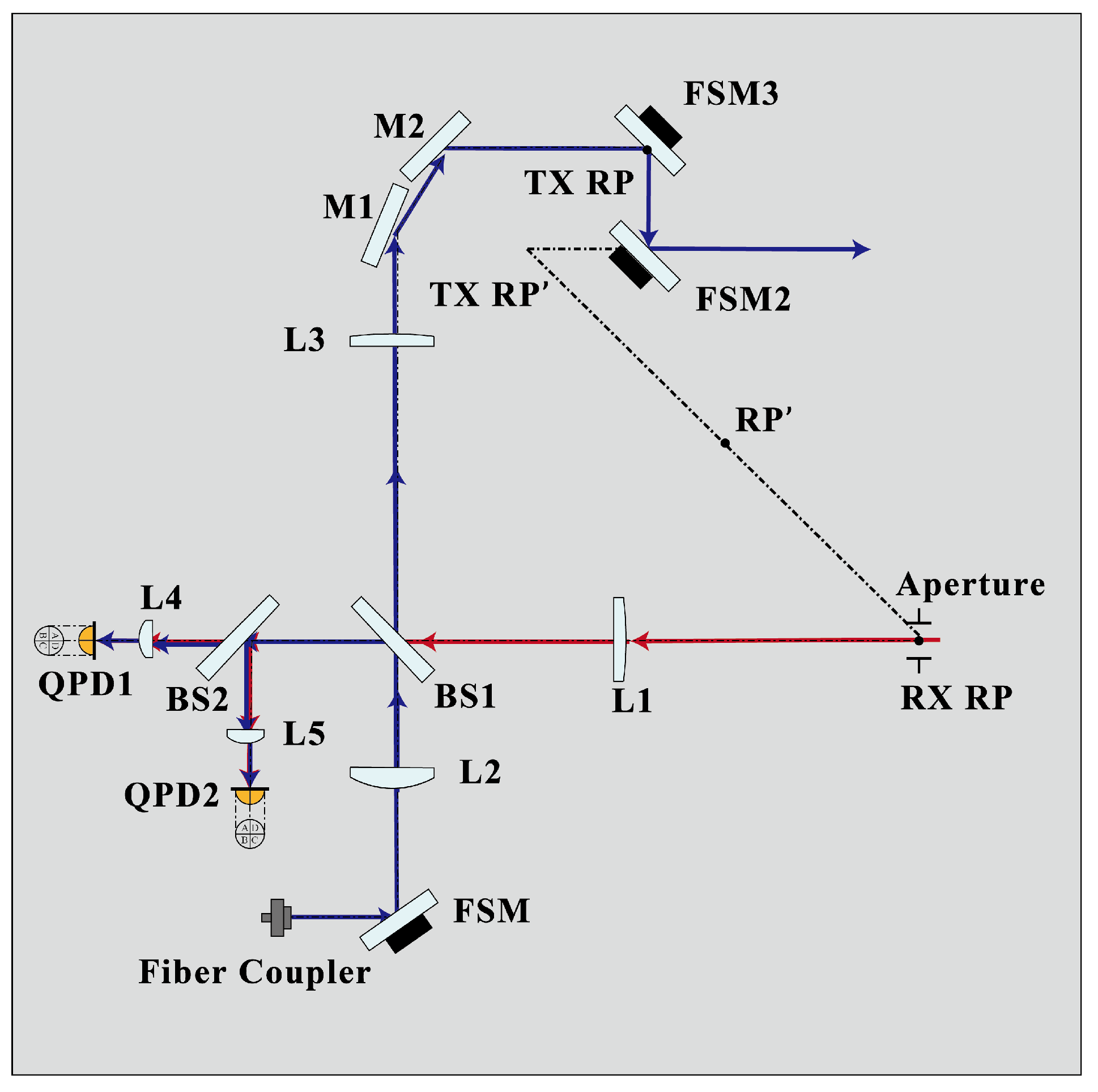
The design of the off-axis optical bench is shown in
Figure 1. Clipped by the receiving aperture, the receiving (RX) beam emitted by the remote satellite transmits through lens L1 and is then split by beamsplitter BS1. Approximately
of the initial RX beam is equally split by beamsplitter BS2, then passes through lenses L4 and L5, respectively, and is then captured by the quadrant photodiodes. The local (LO) Gaussian beam enters the optical bench through a fibre coupler, and the waist of the beam is placed at the surface of the fast-steering mirror (FSM). After passing through lens L2 and being split by BS1,
of the initial LO beam is reflected to BS2 and then interferes with the RX beam, while the majority of the split beam transmits to lens L3 and is then reflected by the rooftop mirrors M1 and M2; it then propagates to the remote satellite. The angle between the rooftop mirrors is set to be
, and both mirrors are perpendicular to the baseplate. In addition, both beamsplitters employed in the optical bench have a wedge of
, which serve to reduce the impact of the back scattered stray light. The reference point of the optical setup is denoted by RP.
The interfering beams are received by the quadrant photodiodes QPD1 and QPD2. The phase signals derived from the beatnotes are then used to calculate the longitudinal pathlength signal (LPS) variations and the differential wavefront sensing signals. An automatic beam alignment system based on the DWS signals is employed in the optical bench in order to compensate the misalignment caused by the attitude jitter of the satellites [
8]. The angular motion of the satellites results in an additional tilt of the RX beam when it impinges on the QPDs. The horizontal and vertical DWS signals are then used to measure the relative angle between the interfering beams, which will be fed back to the FSM mirror. In this way, the LO beam is steered by the FSM, yielding a zero value in the
and
and forcing the interfering beams to be parallel again [
8,
9]. We shall call this process DWS feedback control.
Five keplerian telescope lens systems are employed in this optical layout: L1-L4 and L1-L5 as the RX lens systems; L2-L4 and L2-L5 as the LO lens systems; and L2-L3 as the TX lens systems. The points of rotation of the beams are imagined to the centre of the photodiodes by the lens systems, and the optical path lengths between the front and back focal points of the lens systems are supposed to be unchanged; thus, the beam walk is minimized. In addition, the beams are expanded and compressed through the lens systems, so that the sizes of the beams are adjusted to match the active area of the QPDs [
9]. The front focus of L1 is placed at the centre of the receiving aperture, while the back focal points of L4 and L5 locate at the centre of the active area of the QPDs. The front focal point of L2 is put on the surface of the FSM, and the back focus of L3 is placed at the transmitter reference point (TX RP). The receiver reference point (RX RP) locates at the centre of the receiving aperture, and the centre of the RX RP and TX RP is designated as the reference point (RP) of the optical bench, which is supposed to coincide with the centre of mass (CoM) of the spacecraft, as well as the accelerometer reference point [
8]. The relationship of the angular magnifications among these three lens systems is supposed to be [
9]:
where
denote, respectively, the angular magnifications of the RX, LO, and TX lens systems. The RX and TX beams are maintained to be anti-parallel in the off-axis setup with a combination of lens systems and mirrors, under the control of the DWS feedback loop.
Not all optical components are equal in terms of their impacts on the optical pathlength difference (OPD); some are more equal than others. We divide the optical components into critical and uncritical categories. For the off-axis layout, beamsplitter BS1, the rooftop mirrors, and lenses L1, L2, and L3 are critical components, which should be carefully aligned. Those critical components work as beam combiners as well as components directing the beam to a readout target, whose misalignments will cause a significant variation in OPD [
10]. The alignment of lenses L4 and L5 are less stringent due to a common mode cancellation of the OPD changes of the incident beams. The effect of the misalignment of the FSM is significant on the local optical bench but can be mostly eliminated when considering the global situation. Beamsplitter BS2 may be categorized as a non-critical component which serves only to split the interfering beams and has a negligible impact on the OPD.
Our former work gives a preliminary investigation of the off-axis optical bench by considering a smaller waist radius of 1 mm for the LO beam. To achieve the higher heterodyne efficiency and carrier-to-noise ratio (CNR), the waist radius of the LO beam is enlarged to 2.5 mm, in line with that of the GRACE Follow-on mission, and the parameters of the lenses are chosen to be identical to those of an on-axis optical bench design [
9]. The parameters adopted in the simulation are based on the commercial components shown in
Table 1. The RX beam clipped by the receiving aperture has an approximately flat wavefront and a constant intensity behind the aperture, known as a flat-top beam [
8,
11]. A mode expansion method (MEM) is applied to simulate the propagation of a flat-top beam within the optical bench [
9,
11].
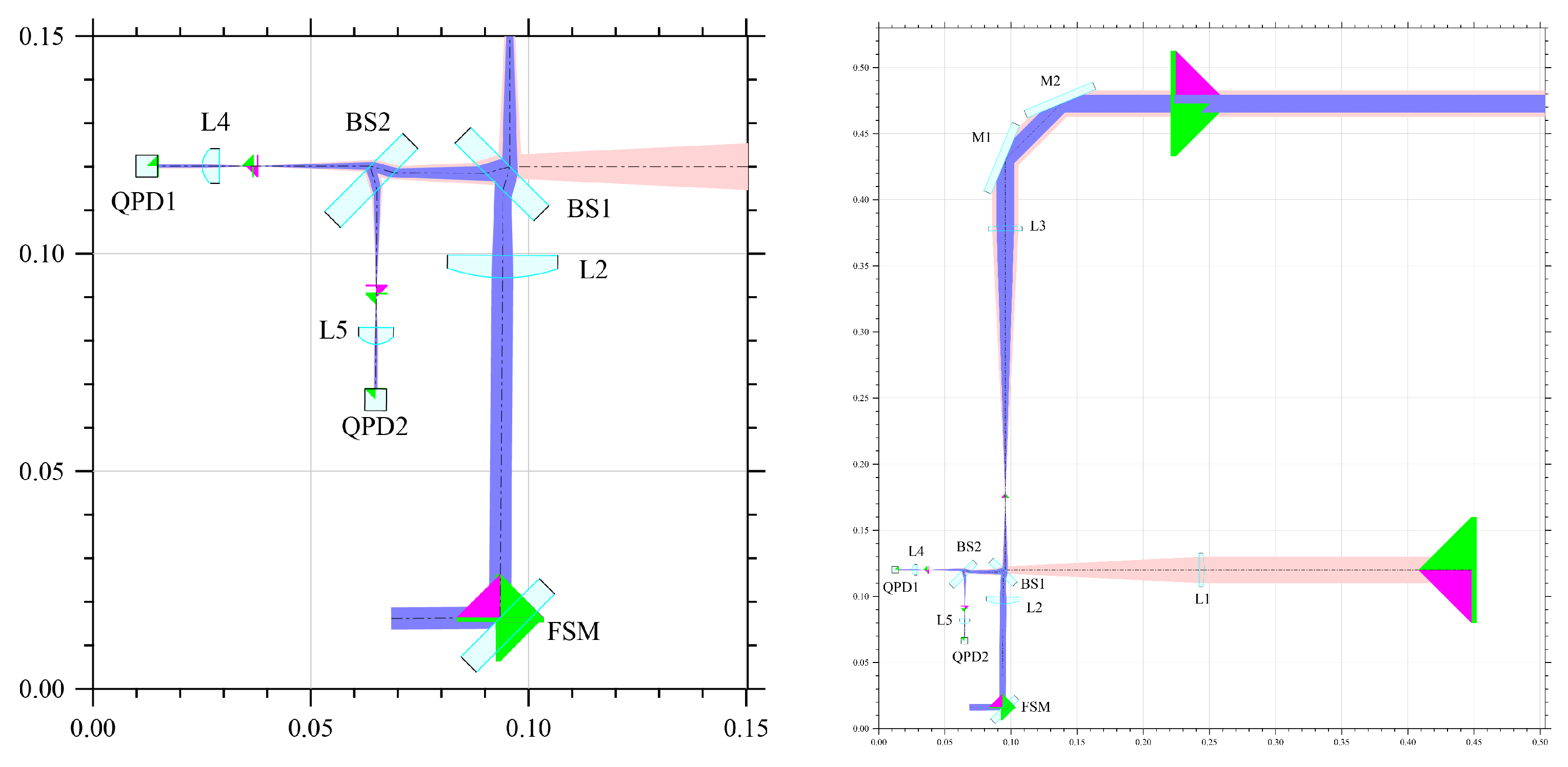
An illustration of the simulated optical bench is given in
Figure 2. All the parameters and results in the simulation are output in double precision.
The initial setup of the components used in the simulation model is depicted in
Figure 2. The off-axis layout is further optimized by adjusting the positions of the lenses, the QPDs, and the receiving aperture [
9]. The position of lens L4 is first adjusted along the optical axis to compensate for the offset between the back focus of lens L4 and the equivalent back focus of lens L1, while the position of lens L5 is adjusted for the same purpose. Lens L3 is then adjusted to compensate for the offset between the back focus of lens L3 and the equivalent back focus of lens L2. The QPDs are fine tuned along the optical axis in order to reduce the beamwalk of the LO beam on the active areas of the photodiodes. As the last step, the receiving aperture is tuned until an optimized TTL coupling is derived, both in yaw and pitch degrees of freedom [
9].
For the off-axis layout, offset exists between the reference point (RP) of the optical bench and the CoM of the satellite, which will result in a variation of OPD when coupled with the attitude jitter of the satellite. The offset may be minimised by an open loop correction mechanism. For the KBR of the GRACE or GRACE Follow-on mission, the manoeuvre is by now quite standard and is usually performed every three to six months. An accuracy of micrometers may be achieved [
13]. However, when we go further up in the LRI ranging sensitivity, the limit of sensitivity for this manoeuvre is not known for the time being. This limit is not determined by the LRI ranging sensitivity alone; star sensor and the rotational degrees of freedom of the accelerometer as well as stability of the satellite platform will also play a role. After a spacecraft manoeuvre to calibrate the reference point relative to the CoM of the satellite [
13], an open loop correction mechanism is activated to correct the offset on orbit. One possible design of this open loop control is to employ two FSMs to control the position of the RP point, as depicted in
Figure 3. It is likely that an alternative design of this open loop control is feasible. This will be further studied in future work.
3. Local TTL Coupling
Angular and lateral jitter of the RX beam during its propagation within the optical bench, termed local TTL coupling, will be addressed in this section. In the simulation model shown in
Figure 4 [
7], the RX beam is tilted in yaw and pitch degrees of freedom and LPS variation is derived, and the local TTL coupling is then calculated. For more description of TTL coupling, see [
9,
14].
To begin with, offsets due to assembly errors of the optical elements and the piston effect [
14] will be considered.
3.1. Transmissive Optical Components
Refractive indices of optical components, the beamsplitters in particular, will generate beam walk on the surface of the photodiode detectors. To investigate the TTL coupling due to the imperfect imaging of the lens systems and the impact of the mismatch between the interfering beams, for our simulation, the beamsplitters are assumed to be made of fused silica with a refractive index of 1.458; the refractive index of mirrors and lenses is chosen to be 1.517, as in N-BK7.
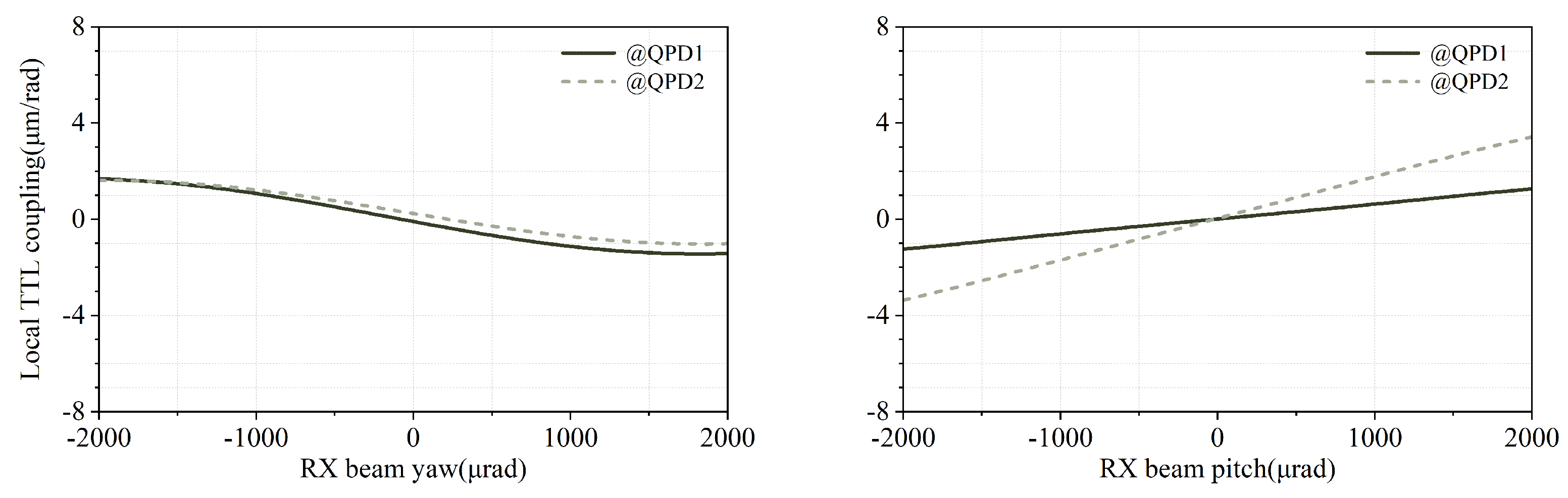
The RX beam is rotated around the RX RP point for
in yaw and pitch degrees of freedom, respectively. With the activation of the DWS feedback loop, the angle between the interfering beams received by the detector is minimised. LPS signals derived from the QPD1 and QPD2 are then calculated and the local TTL coupling noise is obtained. The results are shown in
Figure 5. The figures depict the local TTL coupling in yaw and pitch degrees of freedom.
3.2. Piston Effect
For the off-axis layout, imaging systems are employed to minimize the beamwalk on the photodiodes, and with this setup the lever arm effect is significantly suppressed. We will only consider the piston effect in what follows. Depicted in
Figure 6, piston noise is generated due to the offset between the geometric centre and the pivotal point of the FSM [
14].
The RX beam is rotated around the RX-RP point in yaw and pitch degrees of freedom for
. Local TTL coupling noise results are shown in
Figure 7. For a local piston noise budget of
in both rotational degrees of freedom, the longitudinal offset between the rotation point and its nominal location should be kept under
, while the lateral offset must be kept under
. From the experience in gravitational wave detection, the piston effect can be drastically reduced by a novel design of the FSM actuator, which minimizes the offset between the pivot and the reflection point [
15].
3.3. Misalignment of the Critical Components
To evaluate the impact of misalignments of the optical components due to assembly errors, the positions of the components are slightly shifted along the x, y, and z axes. The RX beam is then rotated around the RX RP point for in yaw and pitch degrees of freedom, and LPS signal variations derived from the QPDs are used to calculate the local TTL coupling. For the off-axis optical bench, QPD2 acts as a redundant detector, and the deployment tolerance of lens L4 is expected to be similar to lens L5, so only the LPS signal derived from the QPD1 is considered.
Depicted in
Figure 8, local TTL coupling is significant in the yaw degree of freedom when L1 is misaligned on the
y-axis and L2 is misaligned on the
x-axis. Significant variations of local TTL coupling also exist in pitch when L1 and L2 are misaligned on the
z-axis. For a positioning accuracy of
in assembling the critical components L1 and L2, local TTL coupling variations due to the misalignment are shown in
Figure 9.
3.4. Summary of the Local TTL Coupling
To end this section, we give a summary of the main sources of the local TTL coupling. The results are shown in
Table 2. The TTL coupling coefficient is given when the RX beam rotates for 2 mrad.
Given the TTL coupling coefficients in the above table together with the attitude variation of a satellite, the LRI ranging error may be obtained. From the GRACE Follow-on data, the attitude variation is at the level of mrad; this generates a ranging error of approximately 20 nm. It is expected that local TTL may be, to a large extent, suppressed by careful assembly of the optical bench and choice of optical components. Further experimental work is needed to further assess the margin of errors for each source.
4. Global TTL Coupling
Due to assembly error, thermoelasticity of the optical bench, and possibly other factors, there is an offset between the reference point and the CoM of the satellite. Apart from the planned drag-free mission by ESA in the joint NASA/ESA mission MAGIC [
16], future NGGM missions will rely on the magnetic torquer for attitude control, supplemented by cold gas thrusters when a magnetic torquer is not working properly. The origins of attitude jitter come mainly from solar pressure, atmospheric drag, and albedo in the pitch direction. The attitude jitter originated from solar pressure gradient, and atmospheric drag will generate random motion of the laser link between two spacecraft. Coupled with the non-zero separation between the reference point and the CoM of the satellite, a global source of TTL is generated between two satellites which, dependent on the offset distance, does not seem to be avoidable. At the same time, the local TTL noise of the optical bench in one spacecraft will propagate with the TX beam to the distant spacecraft and couple with the random attitude jitter of the distant spacecraft. We shall study both sources of global TTL noise in this section.
Due to certain computational limitations of the IfoCAD software employed in this work [
17], the relative motion between satellites is simplified as a single optical bench rotating around the RP point. A remote photodiode is placed 100km away from the TX-RP point, acting as a simplified model of the remote satellite, as depicted in
Figure 10 [
7,
9]. The optical bench layout shown in
Figure 3 is only a possible setup to reduce the offsets between the CoM and the reference point. Our main purpose is to analyze the performance of the optical bench given in
Figure 1. The setup of
Figure 10 is based on the layout described in
Figure 1. The TX beam transmitting from the local optical bench propagates to the remote PD and interferes with a Gaussian beam placed on the surface of the remote photodiode; the beatnote is then captured by the remote photodiode. The Gaussian beam on the remote PD represents the LO beam of the remote optical bench, and the waist radius should be large enough to reduce the effect caused by the wavefront of the beams. As in the previous section, a mode expansion method is employed to study the propagation of a flat-top beam. The global TTL coupling is then obtained by combining the LPS variations derived from the local and the remote photodiodes. In addition, linear regression is employed here to estimate the margin on TTL coupling variation.
4.1. Reference Point Offset and Attitude Jitter
To estimate the TTL coupling noise generated by the coupling of the offset with attitude jitter, the centre of rotation of the optical bench is slightly shifted to a new point away from RP, and the optical bench is rotated around the new centre of rotation for
in yaw and pitch degrees of freedom, respectively. In the case of the GRACE Follow-on mission, The offset between the vertex point of the TMA and the CoM is of the order of
[
18,
19]. We shall set this as the maximum offset in our simulation. At the same time, the proposed optical design contains an open loop that can be used to control the position of RP on orbit (see
Figure 3). Preliminary estimates indicate that the offset may be minimised to the level of
m. We shall study the TTL noise within the range of
and
. Results are shown in
Figure 11.
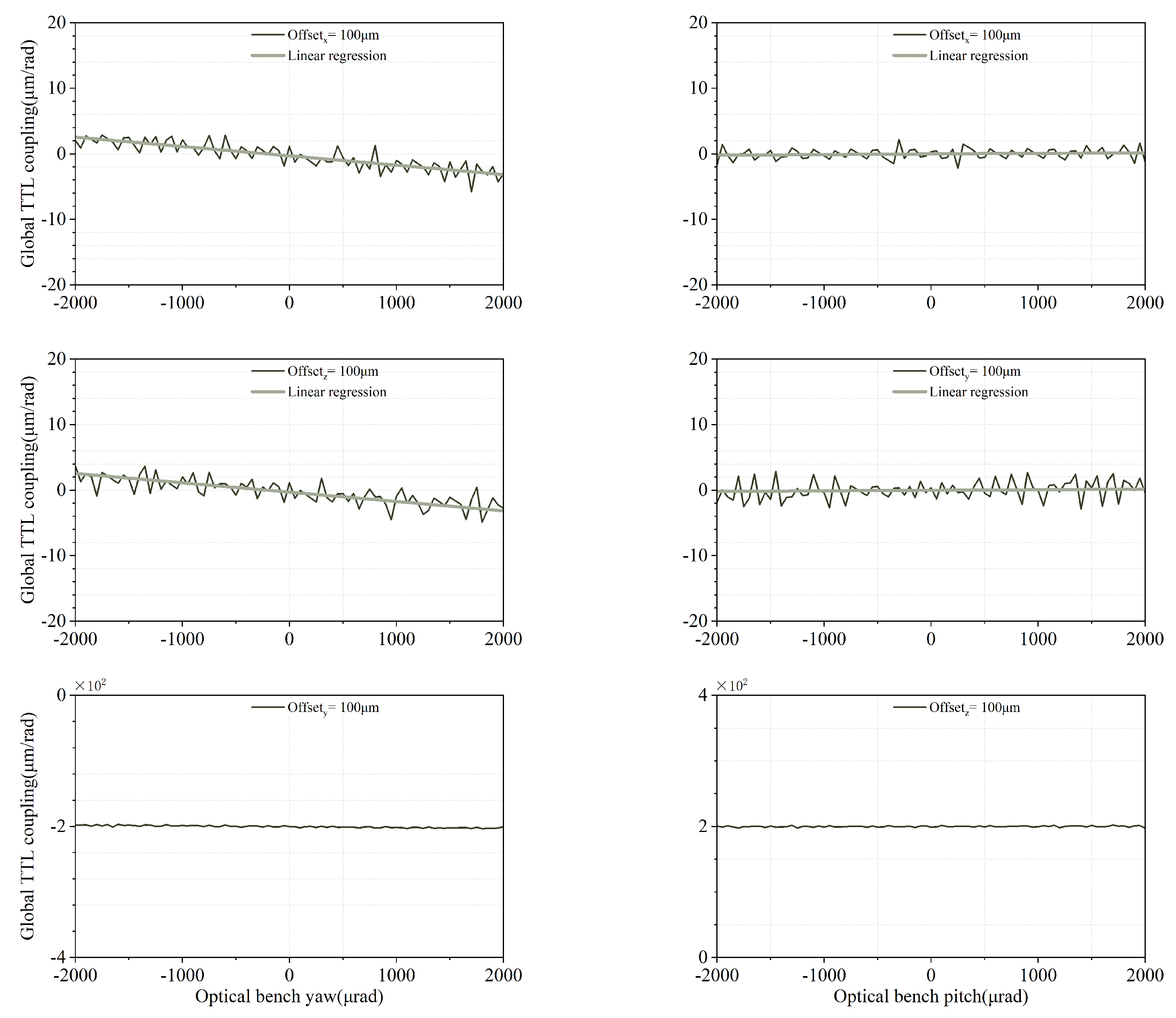
Further simulation results reveal that the global TTL coupling of the pitch degree of freedom is mainly affected by the deviations on the
z-axis, while the change of the global TTL coupling in the yaw degree of freedom is mainly affected by the offsets on the
y-axis, depicted in
Figure 11. For an offset of
in
y and
z, respectively, a global TTL variation of
is generated, which must be suppressed. For the GRACE Follow-on mission, the reference point offset is approximately 100 mm. However, even though this quantity is known after calibration, it can only be subtracted in the 1B data processing. In our design, it is hoped that this offset may be corrected on orbit. The reasons for doing this are as follows. Firstly, with a view that future NGGM and beyond will have better LRI measurement sensitivity to the level of a few tenths of nm, it is not clear whether the standard orbit manoeuvre is able to go under the micrometer level. Secondly, from the perspective of technological development and lessons to be learnt for gravitational wave detection, it would be instructive if we have a way to suppress the reference point offset on board. For a comparison with the GRACE Follow-on mission, given that the attitude jitter is around mrad, a TTL coupling factor of 200 mm per radian will generate 100 nm in LRI ranging error. This is smaller than that of the GRACE Follow-on mission, but still a subtraction in the 1B processing is needed. Offset between the RP and the CoM in the proposed new off-axis design is expected to be reduced to the level of
by an open loop RP correction mechanism in orbit, and results are shown in
Figure 12. According to the parameters used in our IfoCAD simulation, the resolution and the tilt angle of the FSM used in the open loop can be easily achieved by commercial components. Even for commercial products, the resolution can reach approximately 20 nrad. For the piston noise, our experience in gravitational wave detection suggests that we may reduce it to a very low level and will not disturb the nanometer level measurement. The result of micrometer is not a very demanding requirement for an FSM. Currently, we are also looking at an alternative optical method to adjust the reference point offset.
4.2. Attitude Jitter from GRACE Follow-on 1B SCA and GNI Data
To further check on the TTL coupling coefficients calculated, we shall input the GRACE Follow-on 1B SCA and GNI data as our attitude jitter in the simulation, where SCA is the acronym of the star camera assembly and GNI is the trajectory states in the inertial frame [
20]. December 2019 marked the beginning of solar cycle 25. The Sun’s activity has quickly ramped up and is expected to reach a solar maximum in 2025. Among other possible effects on a satellite, the heating of the atmosphere will generate more drag on a satellite and result in worsened attitude jitter. The employment of the GRACE Follow-on 1B SCA and GNI data during this solar active period in our simulation will enable us to understand better in a realistic way the global TTL noise in this suboptimal scenario [
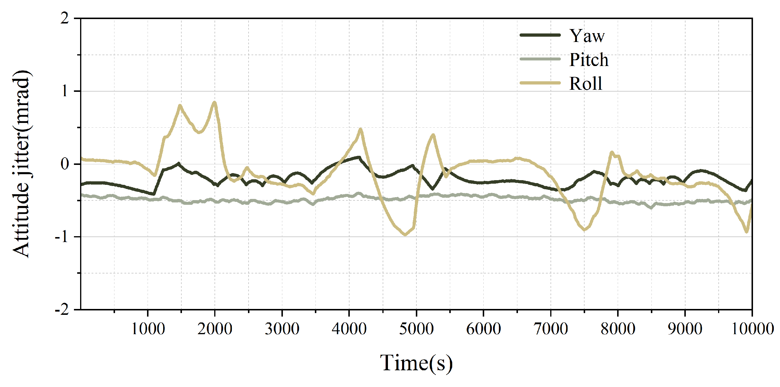
21]. This will help in our mission design in working out a more generous margin for attitude jitter. Data from 00:00:00.00 to 02:46:40.00 on 29 December 2022 is employed.
The attitude jitter used in the simulation is depicted in
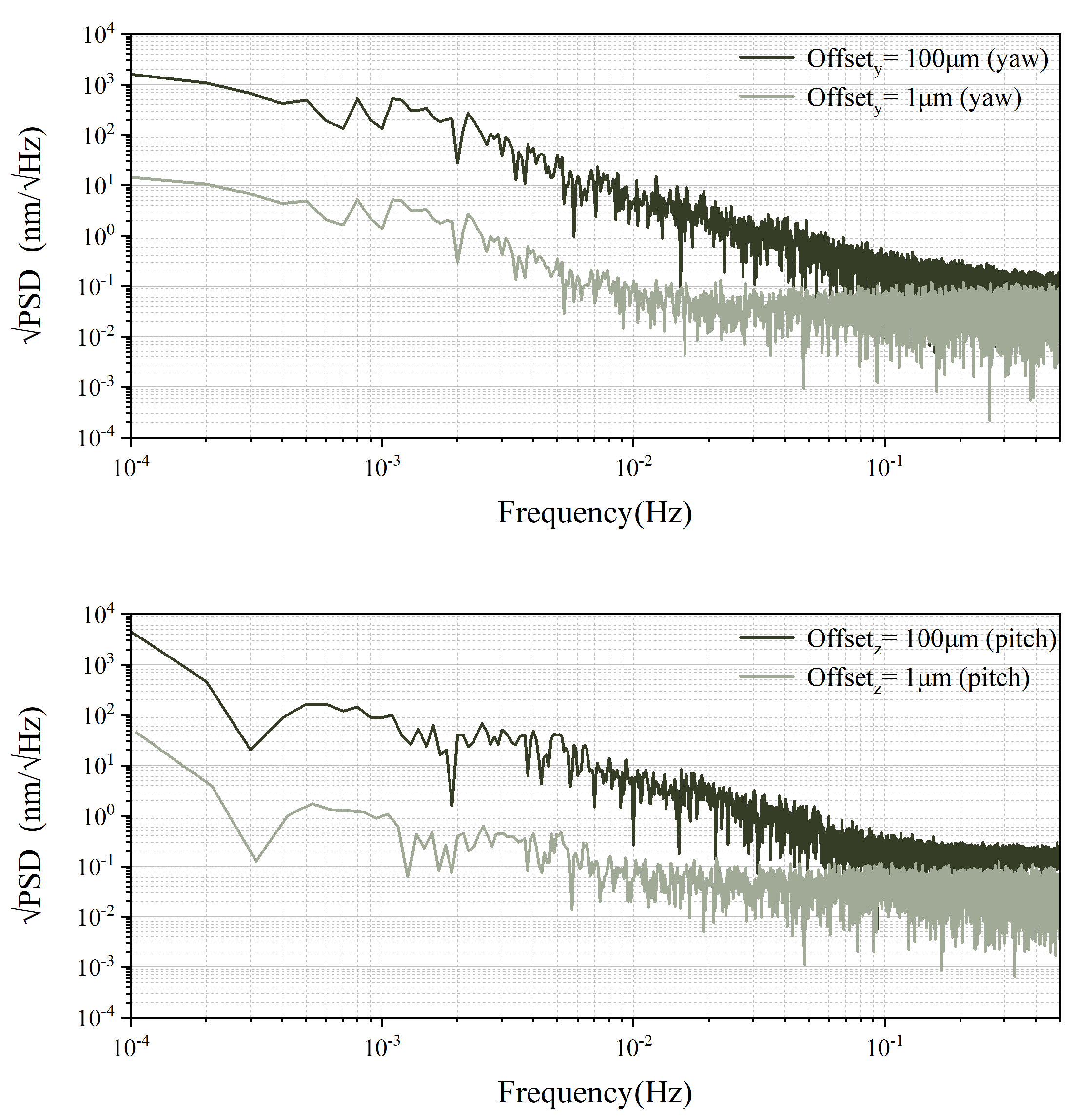
Figure 13. The local optical bench is rotated along the shifted rotation point in yaw and pitch degrees of freedom. The DWS control loop is activated and the LPS signal variation due to the attitude jitter is derived. The power spectral density of the LPS variation is then computed, as given in
Figure 14.
4.3. Cross Coupling between Local and Global TTL
Beam tilt due to local TTL coupling will generate RP point variation, and this in turn will give rise to global TTL when this couples with the relative attitude jitter between two spacecraft. We will evaluate the impact of this cross talk on the global TTL incurred.
4.3.1. Global TTL Coupling and Optical Bench
The TX and LO beams of the off-axis layout originate from the same beam injected by the fibre coupler, which is then split by beamsplitter BS1. When the optical bench rotates, the optical pathlength of the TX beam passing through the BS1 changes, due to the change in the refractive index and the impact of the component wedge. The position of the TX RP then changes, resulting in an offset between the RP and the CoM.
To evaluate the global TTL generated, the local optical bench is rotated around the RP point for
in yaw and pitch degrees of freedom, respectively. LPS variations derived in the local and remote photodiode are calculated. The simulation results are shown in
Figure 15. The figures depict the global TTL coupling generated by the rotation of the local optical bench. The parameters utilized in the simulation are shown in
Table 1.
Torque exerted by non-gravitational force on a satellite will generate jitter in the roll degree of freedom. Due to assembly errors, angular misalignment is generated between the line of sight vector joining the two centres of mass of the two satellite and the laser link. In addition, the principal axes of inertia of the satellite as a rigid body deviate from the satellite body frame, and cross talk exists among different rotational degrees or freedom. These all contribute to the TTL noise in the roll degree of freedom. To estimate the global TTL coupling in roll, an angular offset between the line connecting the RPs and the laser link between satellites is introduced by rotating the local optical bench around the RP point. The optical bench is rotated around the RP point first for
in the pitch degree of freedom and then
in the roll degree of freedom. LPS variations are calculated and the global TTL coupling result is obtained, as depicted in
Figure 16.
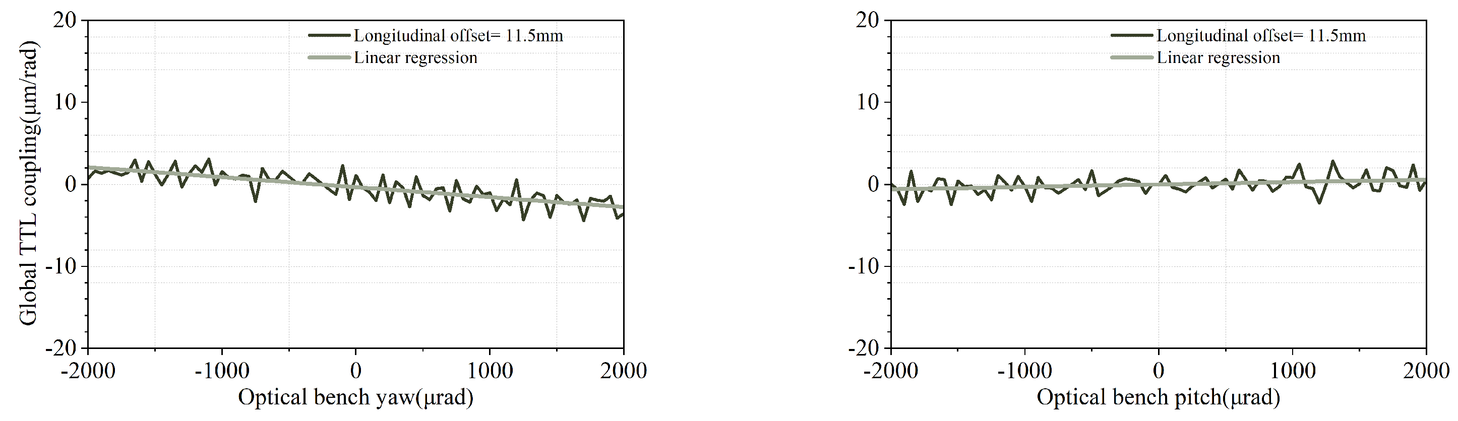
4.3.2. Piston Effect
The phase variation due to the piston effect is carried by the TX beam and captured by the remote PD. For the IfoCAD simulation, the parameter of a commercial S-330 piezo actuator produced by the PI company is used to evaluate the impact caused by the piston effect. The offset between the pivot point and the reflection point of the FSM mirror is set to be 11.5 mm, and the results are given in
Figure 17. The global TTL variation due to the piston effect is much smaller than that of the local situation, even with a larger longitudinal offset between the pivot of the FSM and the reflection point.
4.3.3. Misalignment of the Critical Components
To investigate the coupling between the global TTL coupling and the assembly errors of the local optical bench, misalignment of
for lenses L1, L2, and L3 are considered in the global TTL simulation mode, and the results are shown in
Figure 18.
4.3.4. Misalignment of the Rooftop Mirrors
For the off-axis optical bench design, the angle between the rooftop mirrors is proposed to be
. However, an angular offset occurs due to the assembly error, resulting in an additional OPD variation. For the TMA employed in the GRACE Follow-on mission, the initial beam coalignment is required to be better than
[
22]. The misalignment and non-orthogonality of the three mirrors in the TMA contribute to the anti-parallelism errors between the RX and the TX beams. For the rooftop mirrors, the assembly of the rooftop mirrors is easier and a higher accuracy of beam coalignment is expected to be achieved. To investigate the global TTL coupling due to the misalignment of M1 and M2, offsets of the rooftop mirrors, respectively of
and
, are considered in our simulation. The results are shown in
Figure 19. It can be seen that an offset of
results in a TTL coupling variation of less than
in the yaw degree of freedom, and causes no significant change in the pitch degree of freedom.
4.4. Summary of the Global TTL Coupling
To end this section, a summary is given on the cross talk between local and global TTL coupling in yaw and pitch degrees of freedom, respectively. The results are shown in
Table 3. With a 2 mrad angular jitter, estimates on the margin on TTL coupling variation are given.
Given the TTL coupling coefficients in the above table, together with the data for relative attitude variation between two satellites, the LRI ranging error may be obtained. From the GRACE Follow-on data, the attitude variation is at the level of mrad, and this generates a ranging error of approximately 20 nm. Further suppression of local TTL may reduce the noise budget of global TTL. More experimental work is needed to further assess the margin of errors for each source.

 ,
, 


