Article

An AR Geo-Registration Algorithm for UAV TIR Video Streams Based on Dual-Antenna RTK-GPS

1
Institute of Remote Sensing and GIS, Peking University, Beijing 100871, China
2
School of Space Information, Space Engineering University, Beijing 101416, China
*
Author to whom correspondence should be addressed.
Remote Sens. 2022, 14(9), 2205; https://doi.org/10.3390/rs14092205
Submission received: 30 March 2022 / Revised: 29 April 2022 / Accepted: 29 April 2022 / Published: 5 May 2022
(This article belongs to the Topic GNSS Measurement Technique in Aerial Navigation)

Abstract

:
In emergency response and disaster rescue, unmanned aerial vehicles (UAVs) onboard thermal infrared (TIR) sensors are an essential means of acquiring ground information in the nighttime working environment. To enable field personnel to make better decisions based on TIR video streams returned from a UAV, the geographic information enhancement of TIR video streams is required. At present, it is difficult for low-cost UAVs to carry high-precision attitude sensors and thus obtain high-precision camera attitude information to meet the enhanced processing requirements of UAV TIR video streams. To this end, this paper proposes an improved Kalman filter algorithm to improve the geographic registration (geo-registration) accuracy by fusing the positioning and heading data from the dual-antenna real-time kinematic global positioning system (RTK-GPS) with onboard internal measurement unit (IMU) data. This method can yield high-precision position and attitude data in real time based on low-cost UAV hardware, based on which high-precision geo-registration results can be obtained. The computational complexity can be reduced compared with video stream feature tracking algorithms. Furthermore, the problem of unstable matching due to the low resolution and texture level of TIR video streams can be avoided. The experimental results prove that the proposed method can reduce the registration error by 66.15%, and significantly improve the geo-registration accuracy of UAV TIR video streams. Thus, it can strongly support the popularization and practicality of the application of augmented reality (AR) technology to low-cost UAV platforms.

1. Introduction

Low-cost unmanned aerial vehicle (UAV) platforms have a wide range of applications in emergency rescue and other activities. The use of low-cost UAV platforms to obtain necessary information for emergency rescue and other operations is a trending topic in related research. Most previous research has been based on RGB images and video streams [1,2,3,4]. However, most disaster rescue operations must be performed continuously. Thermal infrared (TIR) sensors are ideal for the acquisition of information at night by collecting thermal radiation from ground objects without additional lighting measures, and for the imaging of ground targets with good stealth; moreover, these sensors can easily be carried by low-cost UAVs.
However, compared with RGB video cameras, TIR cameras have some limitations. For example, they have low resolution, and the appearance of targets may differ significantly from their appearance in RGB video streams. Some distinctive features in the visible band may also become difficult to distinguish in nighttime TIR images. These limitations increase the difficulty of the use of TIR video streams by ground personnel to a certain extent, making it challenging to obtain the state information of the scene solely by relying on UAV TIR video streams. The overlay of existing geo-information onto real-time UAV TIR video streams can provide rich information to describe the on-site situation, which can play a significant complementary and supplementary role to UAV TIR video streams. Therefore, it is of tremendous research significance and application value to simultaneously provide known geo-information in the UAV TIR video stream to front-line operators, which can help commanders establish better situational awareness at night and make better operational decisions [5,6].
There are two main implementation methods of augmented reality (AR) geo-registration based on UAV platforms [7], the first of which is to calculate the position and pose parameters of the camera by tracking feature points in the video stream to stably register virtual targets in the video scene [8,9,10,11]. The second method is to directly use sensors such as internal measurement units (IMUs) to obtain the position and pose parameters of the camera, and then to register virtual targets in the scene [12,13]. A disadvantage of the former method is that it is computationally intensive, and registration information can easily be lost when the camera moves or rotates widely. The disadvantage of the latter method is that it relies on high-precision attitude sensors, which are difficult to afford in terms of price and the load capacity of ordinary UAVs.
The combination of the two methods exploits the strengths of each one and minimizes the impact of their weaknesses. However, in this research work, the algorithms are expected to run directly on UAV platforms, and the main application scenarios are in fields such as emergency rescue. Hence, the computational burden of the equipment must be reduced to the greatest extent, thus making it less challenging to use. Furthermore, when a feature point tracking algorithm is used for TIR video streams, the matching effect is significantly constrained in scenarios such as floods, snow, grassland, and woodland due to the monotonous ground scene. Therefore, in this study, focus is placed on the direct use of a pose sensor to obtain the pose of the camera.
In the authors’ previous study [14], a method was proposed to improve the geo-registration accuracy of UAV video streams based on a real-time kinematic global positioning system (RTK-GPS). However, only the results of RTK single-point localization were used, and the dual-antenna heading data from the RTK system were not further utilized. In the method proposed in the present study, a dual-antenna RTK system is carried on the UAV, and the extended Kalman filter algorithm is also improved to further optimize the UAV attitude results using the RTK output heading data. This improves the accuracy of the DJI UAV position and sensor-based video stream registration from 3 to 1 m.
The remaining sections of this paper are organized as follows. Section 2 reviews the existing related studies, and Section 3 describes the method proposed in this paper. Section 4 describes the experiments and results, and Section 5 analyzes and discusses the experimental results. Finally, this work is concluded in Section 6.

2. Related Research

As stated in the introduction, the main objective of the present research is to implement AR for TIR video streams in nighttime environments. Regarding the existing technical means, TIR video streaming is a mainstream method to provide scene information at night. However, TIR video differs significantly from visible video in terms of its resolution and texture features, as the luminance value is based on the temperature of the object. Moreover, it is characterized by the problems of low resolution and weak texture features compared to ordinary visible video streams. In emergency rescue scenarios, there may also exist large monotonous environments that lack sufficient texture, such as water and snow. Under such conditions, visual tracking-based approaches will result in a large number of mismatches or even no matches. Conversely, real-time feature matching can also increase the computational burden of the onboard devices.
Accurate camera positioning and direction tracking are necessary for AR systems to correctly overlay virtual information onto realistic scenes. The improvement in geo-registration accuracy is a major theme of UAV AR research. The geo-registration accuracy is directly related to the accuracy of tasks such as the positioning of people in the video stream, the determination of the relationship between the location of features and roads, and the estimation of vehicle speeds. Two core ideas have often been adopted to improve the geo-registration accuracy, the first of which is the use of high-precision pose sensors to obtain high-precision camera pose data, thus directly achieving high-precision geo-registration. The second notion is the computer vision-based approach, via which the relative motion between the camera and the ground scenery are restored to obtain accurate camera position and pose data.
Typical research that has adopted the first concept includes the following.
To achieve the all-around texture mapping of buildings in TIR imagery, Stilla et al. [15] used position and attitude data provided by airborne positioning equipment and high-precision inertial navigation equipment for geo-registration. The positioning and attitude sensor system attached to a manned aircraft was found to have an error of less than 1° in the traverse and heading directions and a positioning error of 2.8 m. Using only these sensor data, more desirable geo-registration could be achieved. However, the system uses a high-precision IMU system weighing nearly 3 kg, which is suitable for use on manned aircraft, and the cost of manned aircraft applications is not practical for the vast majority of users.
Because carrying high-precision attitude sensor devices on low-cost UAVs is not currently feasible in terms of either weight and price, the second concept, namely the use of image feature point tracking to achieve geo-registration, has primarily been adopted in previous research. Via this method, satellite positioning data and IMU data are usually combined with computer vision methods to achieve high-precision registration.
Angelino [16] proposed a set of methods in 2012 using Kalman filtering to fuse global navigation satellite system (GNSS), IMU, and computer vision positioning data to provide highly accurate position attitude information for UAVs, which could reduce the average UAV attitude angle error to 1°. However, only simulated data, not actual UAV flight data, were used for experimental evaluation.
In 2015, Chen et al. [17] proposed the augmentation of the vector of locally aggregated descriptors (VLAD) image search algorithm using GNSS positioning information with gravity sensor data to achieve AR geo-registration for mobile devices. However, the VLAD algorithm needs to run on a high-performance server, and the initialization operation during the initial run has an enormous computational burden.
Liu et al. [18] implemented geo-registration through images by matching the features of the camera-acquired frame with laser point clouds of the surrounding environment. The system must operate with high precision and good presentational laser point cloud data. Thus, the generality is not good enough for most application environments. In addition, the study did not provide data such as the camera pose accuracy based on the matching results, and it is unknown whether good registration results can be obtained based on this method.
In 2020, Balázs et al. [19] proposed the use of a combination of topographic data such as digital elevation model (DEM), Shuttle Radar Topography Mission (SRTM), and Advanced Spaceborne Thermal Emission Radiometer (ASTER) data to calculate the skyline of the user’s location and compare it with the skyline extracted from the camera to correct the northward error of a portable compass. The results of experiments demonstrated that this method can reduce the average angular error to 1.04°. However, this method requires an open view of the user’s environment to obtain a high-quality skyline image, and UAVs often do not contain skylines in their ground observation, which also limits the application of this method in the field of UAV AR.
The accuracy of the satellite positioning module used in these previous studies was low. Considering that the location information of the UAV has a significant impact on the registration accuracy in the process of geo-registration, some scholars have attached RTK modules to UAVs to improve the geo-registration accuracy of UAV video streams via low-cost, high-precision measurements.
In 2016, Schneider [20] proposed the use of the simultaneous localization and mapping (SLAM) computer vision algorithm combined with a dual-antenna RTK-GPS system to obtain the accurate attitude of UAVs, and achieved attitude and heading errors of less than 1°, and a centimeter-level localization error. However, this system is mainly used for mapping, and whether it can achieve the desired effect of high-accuracy registration when used in the process of real-time AR requires further investigation. Moreover, the SLAM algorithm has a large computational load and is not suitable for processing TIR video streams.
In addition, some scholars have also equipped RTK modules on UAVs to improve the mapping accuracy of UAVs, which has some implications for this study. For example, Nakata [21] proposed the use of an RTK-equipped UAV for surface displacement monitoring, which was found to achieve an accuracy of 0.1 m for the positioning of ground points using post hoc differencing for assistance. Štroner [22] proposed the use of UAVs equipped with an RTK model for the aerial photography of the ground to achieve centimeter-level mapping results without ground control point correction. Svedin [23] proposed the construction of a low-cost synthetic aperture radar (SAR) remote sensing platform based on RTK technology. Their experiments demonstrated that sub-meter accuracy could be achieved without relying on ground control points.
Although these studies did not directly use AR technology, theory and practice show that carrying RTK positioning modules on UAVs can effectively improve the positioning accuracy of UAVs relative to the ground.
Therefore, in this research, a more desirable geo-registration method on UAV TIR video streams is proposed via the use of only GNSS and IMU sensor data based on a low-cost UAV platform. Based on the preceding review of existing research, the approach based solely on sensor data is a more desirable solution for the use of AR for low-cost UAVs without considering visual tracking. The introduction of the RTK module to the existing UAV sensors can significantly improve the geo-registration accuracy of video streams.
In the authors’ previous research [14], more accurate RTK data than those used by Schneider [20] were used in combination with an improved extended Kalman filter algorithm to improve the UAV positioning and attitude accuracy. However, only RTK localization results from a single antenna were used in that work. In the present research, the utilization of the dual-antenna RTK module in combination with the improved extended Kalman filter algorithm is expected to further improve the UAV registration accuracy.

3. Method

3.1. Augmented Reality Geo-Registration Based on Position and Posture Sensor Data

As mentioned previously, this study is based on the direct geo-registration of UAV TIR video streams from UAVs with satellite positioning and attitude sensors. The basic principle is that the camera in the virtual scene is given the same position, attitude, and viewpoint as the UAV camera. The ground target captured by the airborne camera can overlap with the markers corresponding to the ground target in the virtual scene. The airborne camera usually follows the center projection model, and after the center projection transformation of the lens, the target point on the ground ( X ,   Y ,   Z ) has coordinates ( u ,   v ) on the screen, which can be calculated using the following equation:
[ u v 1 ] = M W S [ X Y Z 1 ]
where M W S is the transformation from the world coordinate system to the screen coordinate system, which includes the transformation matrixes from the world coordinate system to the camera coordinate system, from the camera coordinate system to the projection coordinate system, and from the projection coordinate system to the screen coordinate system. The parameters determining M W S include the three-dimensional position of the UAV ( x u a v ,   y u a v ,   h u a v ) , the traverse, pitch, and heading angles of the camera ( γ , α , β ) , the field of view (FOV) of the camera f o v , and the aspect ratio of the screen a s p e c t . When the camera in the virtual scene is assigned the same parameters as the onboard camera, the conversion matrix M W S of the onboard TIR camera has the same value as the conversion matrix M W S v of the virtual scene camera. This means that the ground point ( X ,   Y ,   Z ) and its counterpart in the virtual space ( X v ,   Y v ,   Z v ) will have the same screen coordinates ( u ,   v ) after projection transformation, and 3D geo-registration is achieved. A detailed description of this content can be found in the authors’ previous study [14].

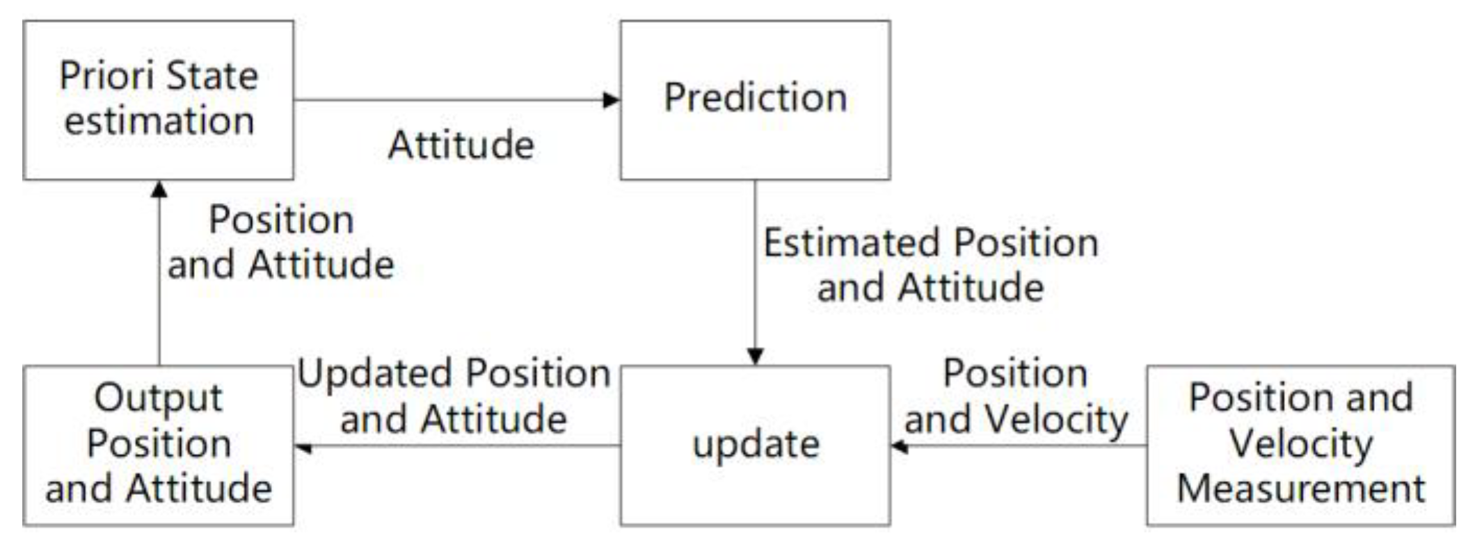
3.2. The Basic Principle of Extended Kalman Filtering

The classical Kalman filter is only applicable to linear systems. However, there are many nonlinear operations in the inertial navigation system model of a UAV. The extended Kalman filter [24] uses Taylor series expansion to linearize the nonlinear model at the operating position, and is usually applied in combinatorial navigation algorithms to combine data from different sensors.
The working process of the Kalman filter consists of the following two main parts. (1) First, the current state of the system, including the uncertainty, is predicted. (2) When new measurements containing errors and noise are input, the prediction of the system state is updated using the weighted average of these measurements, and more accurate measurements receive a higher weight. As shown in Figure 1, this process is recursive, can be run in real time, and requires only the current measurements and predictions from the previous step and its uncertainty matrix, not more historical data.

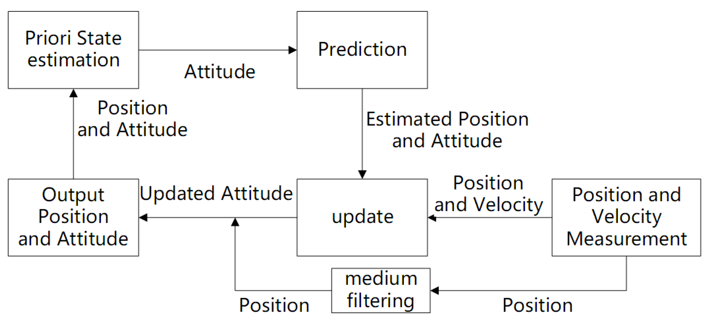
3.3. An Improved Extended Kalman Filter Algorithm with RTK Heading

RTK positioning data are usually highly accurate and can be approximated as accurate measurements relative to the usual operating range of UAVs. In the authors’ previous work [14], the extended Kalman filter algorithm described in another study [25] was purposefully improved to make better use of the high-accuracy RTK positioning results. In the standard Kalman filter algorithm, most of the input data from various sensors are unreliable measurements with large confidence intervals. Thus, it is necessary to initialize the Kalman filter using the corresponding error parameters, and to cyclically update the error parameters while the Kalman filter is operating. The measurements must then be corrected using the error parameters. In this work, the authors consider the measurements of RTK-GPS receivers to be reliable due to their high accuracy.
Because the error parameters are dynamically updated while the program is running, simply initializing the Kalman filter according to the confidence interval of the RTK data will not effectively exploit the high-accuracy characteristics of the RTK data, and will increase the uncertainty in the filtering process. Therefore, the improved extended Kalman navigation algorithm retains only the filtered attitude data for the next cycle after each cycle of the Kalman filtering operation. The position of the next cycle of the Kalman filtering operation directly uses the RTK position after median filtering.
In this study, the heading angle obtained from RTK dual-antenna orientation measurements is added to the extended Kalman filter model to further improve the UAV attitude measurement accuracy The workflow of the improved extended Kalman filter algorithm is shown in Figure 2.
As shown in Figure 6, the RTK receiver is equipped with dual antennas, and the heading angle of the UAV can be determined by using the positioning data from the dual antennas during positioning. Most previous studies on navigation algorithms using dual-antenna orientation assumed that the original positioning message of each antenna is available in its entirety. Therefore, the measurement state of each antenna can be separately incorporated into the working model of the Kalman filter, and the measurement error for the measurement state of each antenna can be separately corrected during the working process. Moreover, the attitude measurement results of the system can be corrected according to the relative position of the antenna installation. As a typical low-cost UAV RTK receiver, the dual-antenna RTK receiver used in this study directly outputs the heading angle derived using the dual antennas, instead of providing the original positioning information of each antenna. Targeted improvements to the extended Kalman filter navigation algorithm are required to address this condition. The algorithm can directly accept RTK dual-antenna heading values as input values for processing.
The addition of the RTK heading values to the extended Kalman filter requires that the heading values be used as new observations. Correspondingly, the dual-antenna heading angle measurements from the RTK module must be added to the matrix containing the new measurements at each cycle, and the matrix of satellite positioning measurements in an extended Kalman filter is usually as follows:
δ y G N S S = [ δ y v e l o c i t y δ y p o s i t i o n ]
where:
δ y v e l o c i t y = [ v p r e d i c t e d n a v i v G P S n a v i ]
δ y p o s i t i o n = T p r [ p p r e d i c t e d n a v i p G P S n a v i ] + C b o d y t o n a v i l b o d y t o a n t e n n a ,
T p r = [ R M + h 0 0 0 ( R N + h ) c o s ( l a t ) 0 0 0 1 ] ,
where δ y is the observed state of the system, δ y v e l o c i t y is the observed 3D velocity error, v p r e d i c t e d n a v i is the airframe velocity estimated by inertial navigation, and v G P S n a v i is the airframe velocity obtained from GPS measurements. Moreover,   δ y p o s i t i o n is the observed 3D position error, p p r e d i c t e d n a v i is the body position estimated by inertial navigation, p G P S n a v i is the body position measured by GPS, C b o d y t o n a v i is the transformation from the body coordinate system to the world coordinate system matrix,   l b o d y t o a n t e n n a is the GPS antenna installation position, T p r is the conversion matrix from latitude and longitude to the right-angle coordinate system, R M is the meridian radius of the Earth, R N is the normal radius of the Earth, and h is the height of the airframe relative to the reference ellipsoid.
After adding the heading angle obtained from the RTK measurements, the input matrix of the system is increased by the azimuth error δ y y a w , and the input matrix becomes:
δ y R T K _ y a w = [ δ y y a w δ y v e l o c i t y δ y p o s i t i o n ]
where:
δ y y a w = ψ p r e d i c t e d n a v i ψ R T K n a v i
where ψ p r e d i c t e d n a v i is the UAV heading angle calculated by the IMU based on the UAV angular velocity, and ψ R T K n a v i is the UAV heading angle obtained by the RTK receiver via dual-antenna positioning.
The measurements input to the system must be multiplied by the measurement matrix, which, in the original Kalman filter algorithm, is as follows:
H G P S = [ 0 I 0 0 0 0 0 T p r 0 0 ]
where I is a 3 × 3 unit matrix and 0 is a 3 × 3 matrix. The first column corresponds to the attitude measurements in the measurement matrix, the second column corresponds to velocity measurements, and the third column corresponds to position measurements. Therefore, the improved measurement matrix must include a row at the top that corresponds to the heading measurements.
The measurement matrix is modified as follows:
H R T K _ y a w = [ 0   0   1 0   0   0 0   0   0 0   0   0 0   0   0 0 I 0 0 0 0 0 T p r 0 0 ]
In the newly added row, element 1 corresponds to the newly added directional difference δ y y a w , which in turn makes the dimension of H R T K _ y a w correspond to δ y R T K _ y a w .
Correspondingly, the uncertainty matrix R must be changed according to the previous changes. The original uncertainty matrix is as follows:
R G P S = [ δ G P S v e l o c i t y 2 0 0 δ G P S p o s i t i o n 2 ]
After adding the heading measurements, the uncertainty matrix must also be increased by the uncertainty term corresponding to the heading measurements and kept in a diagonal form, and is changed to:
R R T K _ y a w = [ δ R T K y a w 2 0 0 0 δ G P S v e l o c i t y 2 0 0 0 δ G P S p o s i t i o n 2 ]
where δ R T K y a w 2 is the variance of the RTK dual-antenna heading angle.
By using the improved extended Kalman filter algorithm, the dual-antenna RTK heading can be added as an additional measurement for the filtering operation. Compared with the improved Kalman filter algorithm, the UAV attitude angle is no longer constrained indirectly by the GPS position and the airframe motion state, but directly by the input RTK dual-antenna orientation result, and thus a relatively accurate UAV attitude angle can be obtained. Based on the airframe attitude data, an accurate airborne camera attitude can be derived.
Because the UAV body is connected to the camera using a three-axis gimbal, the three-axis gimbal can stabilize the camera attitude in the roll and pitch axis directions while following the body movement in the heading axis, which causes the roll and pitch angles of the camera to remain stable when the user does not input a rotation command. Moreover, in the heading axis direction, the camera heading remains in line with the UAV fuselage when the UAV fuselage is not rotating horizontally. In contrast, when the UAV fuselage is rotating, the camera follows the UAV fuselage rotation with a particular speed difference. The UAV determines the rotation angle of the camera relative to the fuselage through the code dial, which is combined with the attitude of the fuselage to deduce the attitude of the camera in the navigation coordinate system.
The detailed steps for the AR geo-registration of the UAV TIR video stream using these data have been described in the authors’ previous study [14].

3.4. Camera Pose Calculation for Geo-Registration

According to the extended Kalman filter algorithm described in Section 3.3, the attitude of the UAV body can be calculated. The onboard camera is connected to the UAV through the gimbal, which compensates for the shaking of the UAV during the flight process. The three-axis angle of the onboard camera relative to the airframe can be read according to the code dial on the gimbal. The camera pitch and roll axes are relatively constant, while the heading angle changes more frequently during flight and is more susceptible to interference. Therefore, among the three-axis attitude angles of the camera, the pitch and roll angles can be calculated using the original values provided by the flight controller, and the heading angle is based on the airframe heading angle obtained by the method described in Section 3.1.
A T T c a m e r a = [ φ c a m e r a θ c a m e r a ψ E K F + ψ c o d e r ]
where φ c a m e r a and θ c a m e r a are, respectively, the camera roll angle and pitch angle given directly by the UAV flight control, ψ E K F is the body heading angle obtained by the improved extended Kalman filter algorithm, and ψ c o d e r is the heading angle difference between the UAV body and the camera obtained by the gimbal code disk. After determining the three-dimensional position and three-axis attitude of the UAV, the AR geo-registration of the UAV TIR video can be performed.

3.5. Error Analysis of Position and Attitude Sensor Data for Geo-Registration

From the discussion in the previous section, it is clear that obtaining accurate camera positions and poses is a prerequisite for achieving accurate geo-registration. The geo-registration of UAV TIR video relies on the 3D position of the UAV and the attitude of the onboard camera. UAV position and attitude errors can lead to errors in the registration results. On the other hand, camera imaging errors can also impact the registration results, so the errors arising from the imaging process must also be considered when performing error estimation. The registration error can thus be expressed as:
E r e g = E r e g C a m P o s i t i o n 3 D + E r e g C a m A t t i t u d e + E r e g L e n s D i s t o r t i o n
where E r e g C a m P o s i t i o n 3 D is the effect of the camera position on the registration accuracy, E r e g C a m A t t i t u d e is the effect of the camera attitude error on the registration accuracy, and E r e g L e n s D i s t o r t i o n is the effect of camera lens distortion on the registration accuracy. The pitch and roll axes of the camera are kept stable by the gimbal, and the correction of the camera attitude is only for the camera heading angle; thus, E r e g C a m A t t i t u d e can be simplified to E r e g C a m Y a w , which is the effect of the camera heading angle on the registration accuracy. The effect of camera lens deformation on the registration accuracy is compensated by the calibration result of the lens. In comprehensive consideration of these factors, the factors that affect the registration accuracy considered in this study are as follows:
E r e g = E r e g C a m P o s i t i o n 3 D + E r e g C a m Y a w
In Figure 3, B is the location of the camera, and its 3D coordinates are ( x c a m , y c a m , h c a m ). Moreover, AB is the central optical axis of the camera, the plane ACD is the ground, and D is the target point in the image. The pitch and heading angles of the camera are α c e n t e r and β c e n t e r , respectively. The coordinates of the point D on the ground can be expressed as:
X D = x c a m y i m sin α c e n t e r + h c a m x i m cos β c e n t e r f x c a m cos α c e n t e r f cos α c e n t e r y i m sin α c e n t e r f h c a m sin α c e n t e r sin β c e n t e r + h c a m y i m cos α c e n t e r sin β c e n t e r f cos α c e n t e r y i m sin α c e n t e r Y D = f y c a m cos α c e n t e r + h c a m x i m sin β c e n t e r y c a m y i m sin α c e n t e r f cos α c e n t e r y i m sin α c e n t e r + f h c a m sin α c e n t e r cos β c e n t e r + h c a m y i m cos α c e n t e r cos β c e n t e r f cos α c e n t e r y i m sin α c e n t e r
where ( X D ,   Y D ) is the ground coordinate of the point ( x i m , y i m ) in the image, the original point of the screen coordinate system is at the center of the image. f is the focal length in pixel of the lenses. Because the camera is kept stable in the transverse roll and pitch directions by the gimbal, the transverse roll direction can be regarded as horizontal, and the pitch angle can be regarded as a stable value. It can be seen from Equation ( 15 ) that the accuracy of the target location is affected by camera location ( x c a m ,   y c a m ,   h c a m ) and the yaw of the camera β c e n t e r . Therefore, the error caused by these factors can be estimated with Equation ( 15 ).

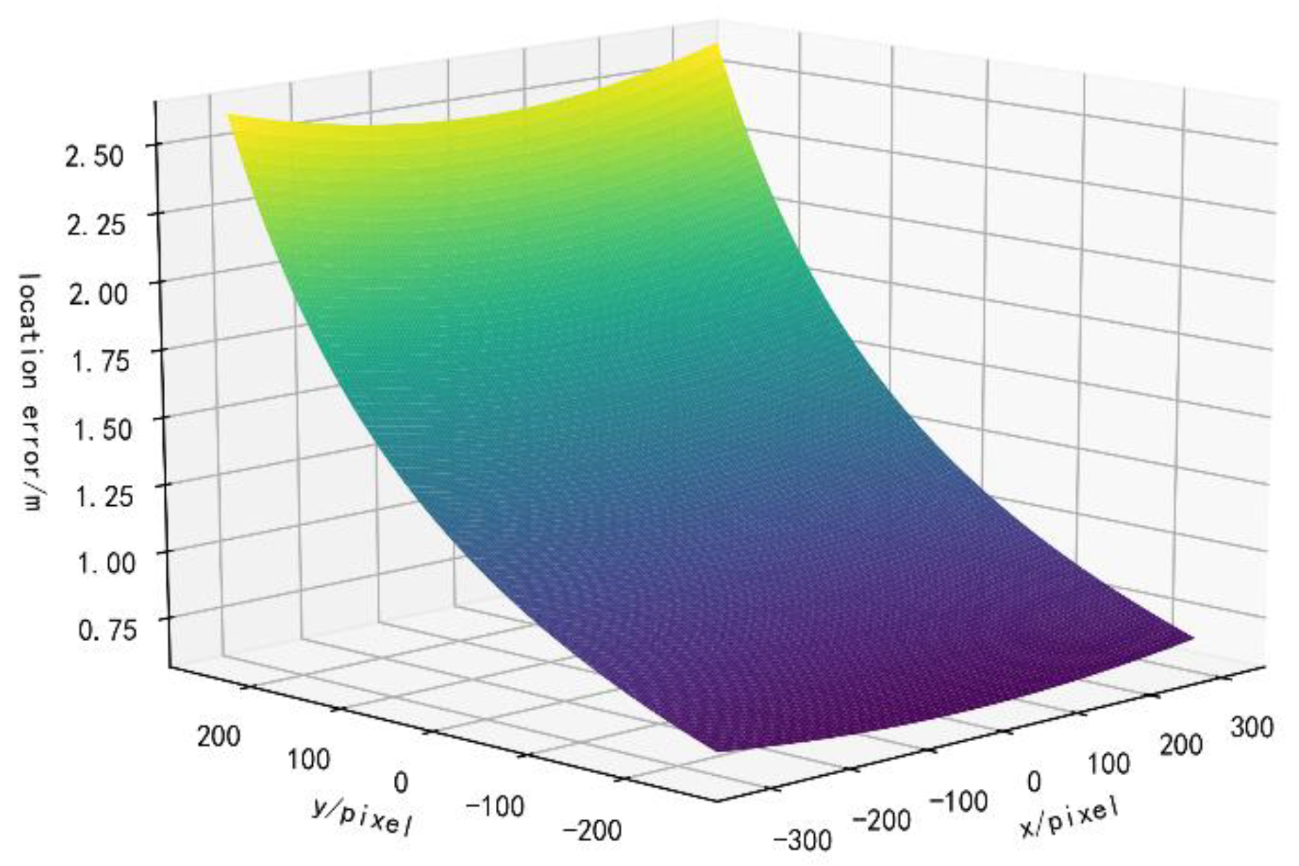
3.5.1. The Effect of the Camera Position Error on the Registration Accuracy

The effect of the camera position error on the registration accuracy is:
E r e g C a m P o s i t i o n = [ E X c a m E Y c a m ] .
where E X c a m and E Y c a m are the positioning errors of the camera, which are equal to the UAV positioning error. Moreover, E p o s i t i o n C a m P o s i t i o n is the registration accuracy error generated by the GPS positioning error, and its scalar value is as follows:
|| E r e g C a m P o s i t i o n || = E X c a m 2 + E Y c a m 2

3.5.2. The Effect of the Camera Height Error on the Registration Accuracy

The positioning error of the ground point D caused by the height error is:
E r e g C a m H e i g h t = [ X D h c a m Y D h c a m ] E h c a m
where E h c a m is the positioning error of the UAV in the vertical direction. The scalar length of E r e g C a m H e i g h t is as follows:
|| E r e g C a m H e i g h t || = E h c a m ( X D h c a m ) 2 + ( Y D h c a m ) 2

3.5.3. Effect of the Camera Attitude Error on the Registration Accuracy

The camera attitude includes three directions, namely the pitch, roll, and heading directions. Because the pitch and roll axes of the airborne camera used in this study are stabilized by the gimbal, the actual attitude direction that changes with the UAV motion and affects the registration accuracy is the heading direction. The positioning error of ground point D caused by the camera heading is:
E r e g C a m Y a w = E β || C D ||
where E β is the camera heading angle error. The scalar length of E p o s i t i o n C a m Y a w is as follows:
|| E r e g C a m Y a w || = E β h c a m f 2 cos ( α c e n t e r ) 2 2 f y i m sin ( α c e n t e r ) cos ( α c e n t e r ) [ f sin ( α c e n t e r ) + y i m cos ( α c e n t e r ) ] 2 + x i m 2 + y i m 2 sin ( α c e n t e r ) 2 [ f sin ( α c e n t e r ) + y i m cos ( α c e n t e r ) ] 2
As can be seen from Equations ( 19 ) and ( 21 ), due to the different distances of the ground objects in the image relative to the camera, the registration error caused by the camera height and the camera heading error at each part of the picture will vary with the distance between the object and the camera. When the ground target is farther away relative to the camera, the influences of the camera height and the camera heading error on the registration accuracy increase. The effects of the camera height and the camera heading error on the registration accuracy decrease when the ground target is closer to the camera. To estimate the theoretical value of the geo-registration error based on Equations ( 17 ), ( 19 ) and ( 21 ), the horizontal camera positioning error ( E X c a m ,   E Y c a m ), the vertical camera positioning error h c a m , and the camera heading angle error E β must be calculated or obtained from the UAV datasheet.
Due to the high accuracy of RTK data, they can be used as the true values. The root-mean-square error (RMSE) between the UAV position obtained by RTK measurement and the UAV flight control output based on ordinary GPS data can be used as the value taken when estimating the theoretical value of registration error ( E X c a m ,   E Y c a m ). Similarly, the RMSE between the altitude measured by the RTK module and the altitude output by the flight control can be used as the estimated value of h c a m , and the RMSE between the RTK heading and the flight control output can be taken as the value of E β . The formula for calculating the RMSE is as follows:
e R M S = j = 1 n p o i n t s ( v a l u e j r e s u l t v a l u e j g t ) 2 n p o i n t s
In Equation ( 22 ), n p o i n t s is the number of sampling points, v a l u e j g t is the standard value of the j th sampling point, and for E X c a m , E Y c a m , and h c a m , v a l u e j g t is the value of the corresponding item using the RTK module. Moreover, v a l u e j r e s u l t is the measured value using a regular GPS receiver. For E β , v a l u e j g t is the camera heading value after filtering by the proposed method, and v a l u e j r e s u l t is the camera heading value given directly by the UAV flight control system. The calculation results are reported in Table 1.
According to Table 1, during the flight, the root-mean-square positioning errors of the UAV in the horizontal direction obtained using the RTK and ordinary GPS receivers were respectively found to be E X c a m = 1.2846   m and E Y c a m = 0.9342   m . The registration error caused by the UAV positioning error was found to be || E r e g C a m P osition || = 1.5884   m . Similarly, the root-mean-square positioning error of the UAV in the vertical direction obtained using the RTK module with a normal GPS receiver was found to be h c a m = 2.8017   m .
The distribution of the registration error within the camera FOV due to the height error is shown in Figure 4.
As shown in Figure 4, the distribution of registration errors caused by altitude error in the camera FOV was found to increase with the distance of the ground target from the camera, and the average error in the camera FOV was 5.6036 m. In practice, for the convenience of target point selection, most of the positioning operations will be performed closer to the camera, and the measured error may be lower than the average value in the FOV. According to the flight parameter setting, namely the UAV flight height h c a m = 20 m, Figure 5 presents the error distribution generated by the camera heading angle within the camera FOV calculated by Equation ( 21 ). The theoretical average value of the error generated by the camera heading angle within the camera FOV was calculated to be 1.2497 m. In comprehensive consideration of these results, the theoretical estimates of the registration error due to the camera horizontal positioning error, vertical positioning error, and camera heading angle error are reported in Table 2.
As shown in Table 2, the experimental data that have the most significant impact on the registration results were found to be the camera height error data; however, this calculation is based on the average value of the camera FOV. In practice, the objects farther away occupy a smaller area due to the influence of the perspective projection on the screen, and have lower availability. Thus, the targets closer to the camera have a higher significance, and the actual measurement of the error may be lower than this estimate.

4. Experiments

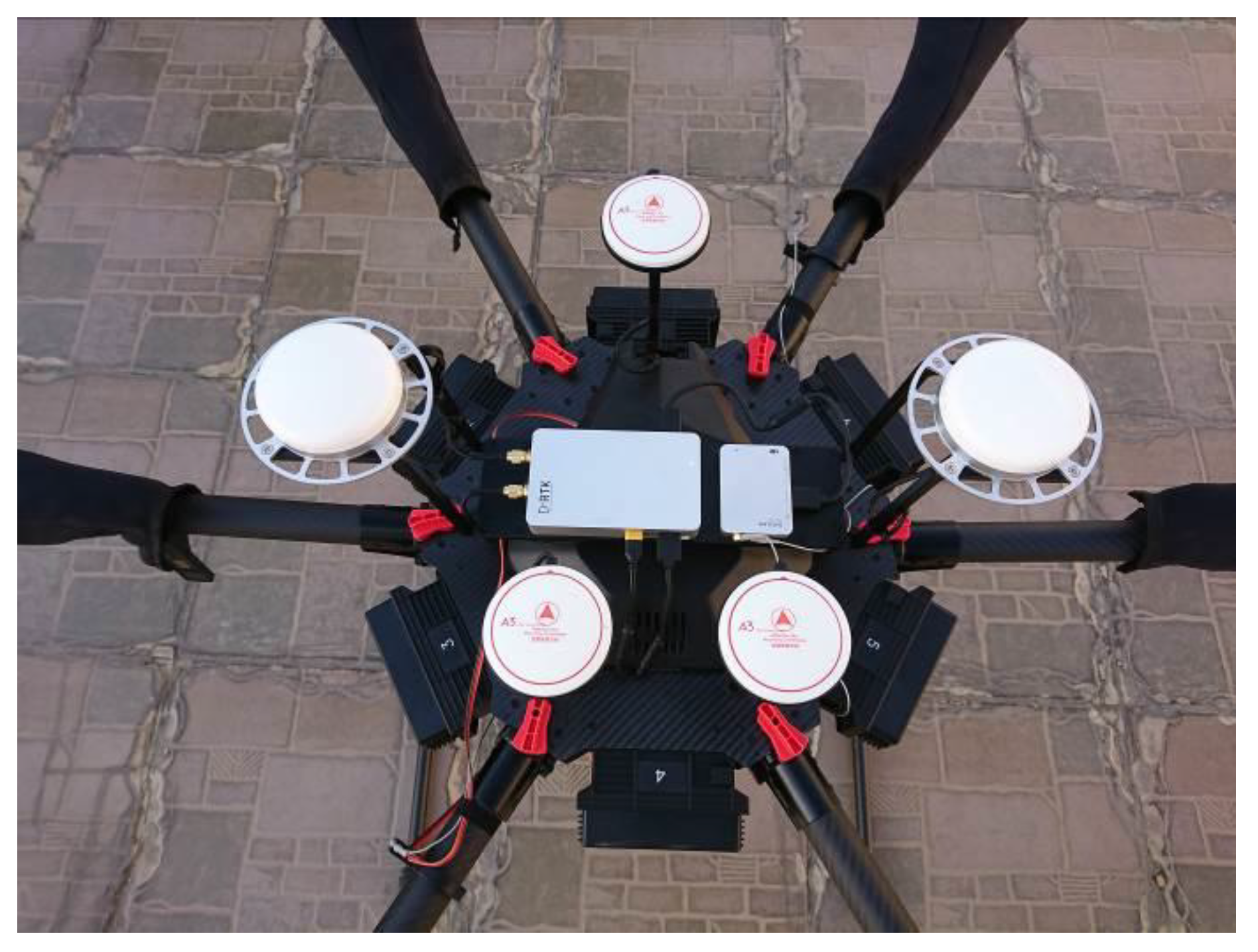
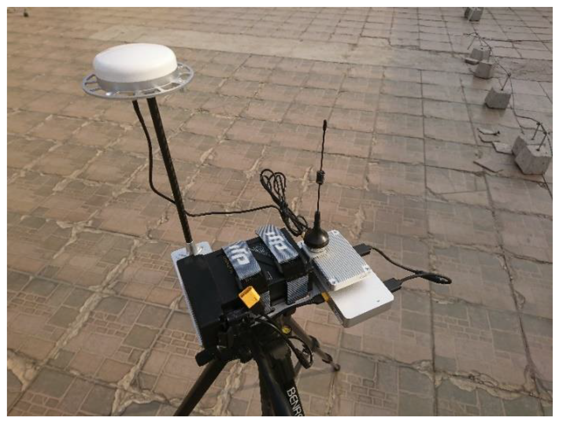
4.1. Experimental Platform

The UAV platform used in this study was the DJI M600 UAV [26], which is a six-axis, multi-rotor UAV that can be equipped with various types of sensors. Furthermore, the UAV can be fitted with RTK positioning kits for more accurate positioning. The performance indicators of the UAV are reported in Table 3.
The DJI M600 UAV can carry various payloads depending on the mission, including RGB cameras, TIR cameras, and any custom sensor that meets the weight and size requirements, via a comprehensive gimbal system.
The XT2 TIR sensor used in this study has a dual TIR/visible imaging function, which can simultaneously capture TIR and visible images and video streams. Its specific specifications are reported in Table 4.
As shown in Figure 6, the M600 UAV can be equipped with a D-RTK differential GPS kit, which enables the more accurate positioning of the UAV and can acquire a UAV heading based on the dual-antenna orientation. This differential GPS kit has a horizontal positioning accuracy of 1 cm + 1 ppm and a vertical positioning accuracy of 2 cm + 1 ppm [28]. The D-RTK has a heading accuracy of (0.2/R)°, where R is the distance in meters between the two antennas at the sky end. The distance between the two antennas is approximately 0.5 m when the D-RTK is installed on the M600 fuselage, so the orientation accuracy is about 0.4°. However, the D-RTK kit only provides a dual-antenna directional output of 1°, so it cannot independently rely on the RTK dual-antenna lateral direction to provide accurate UAV heading information. The differential ground station of the D-RTK suite is shown in Figure 7.

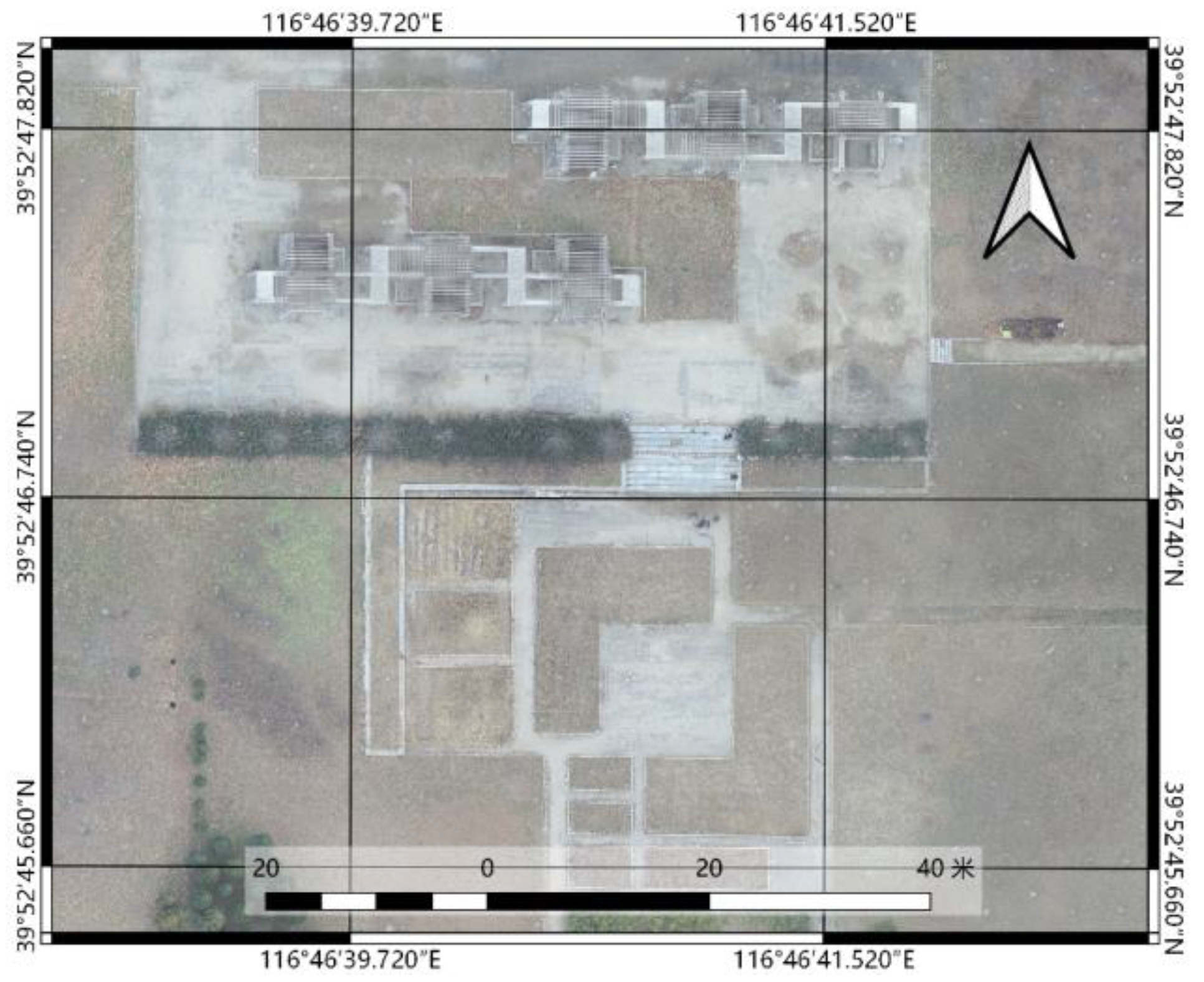
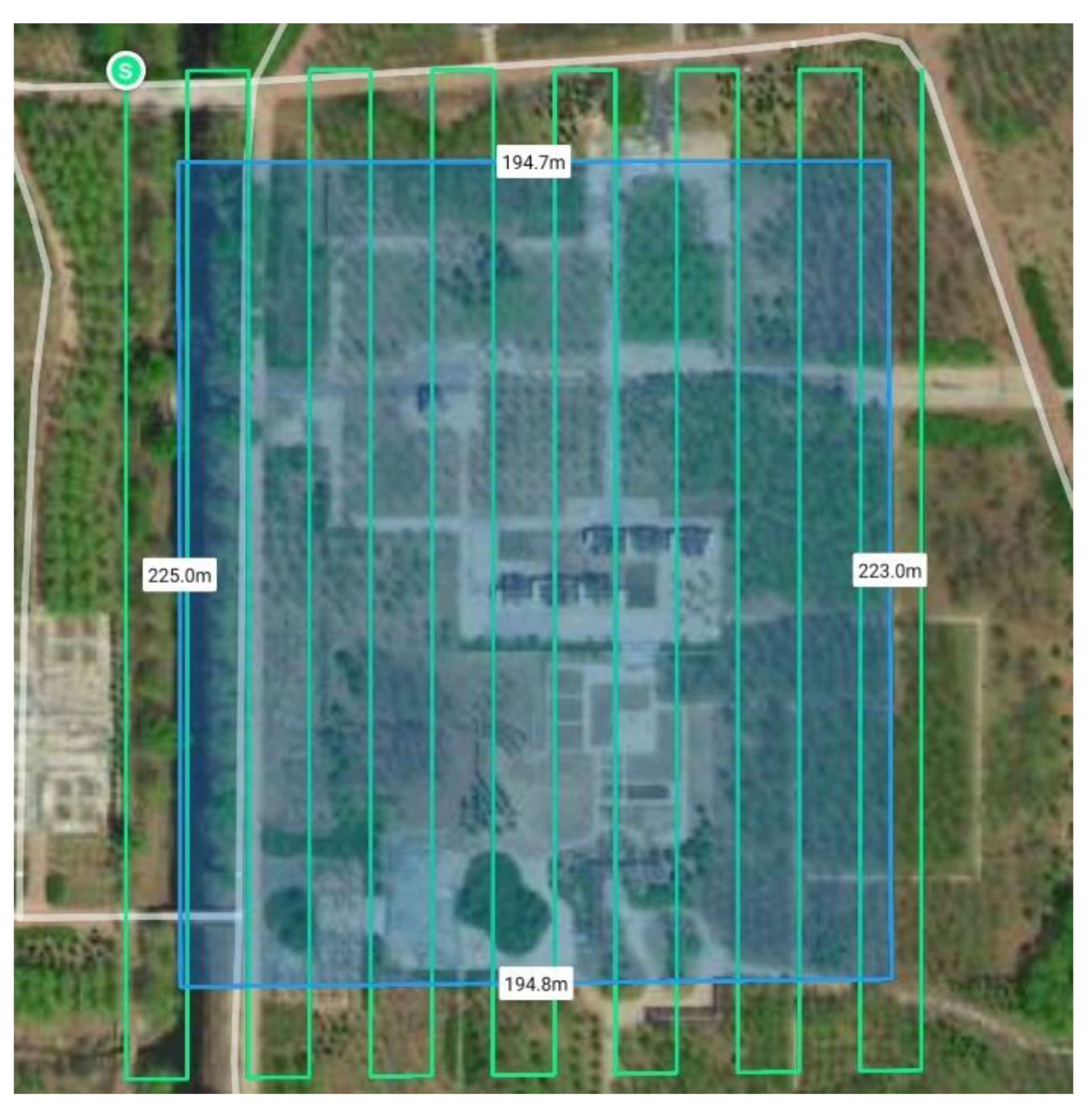
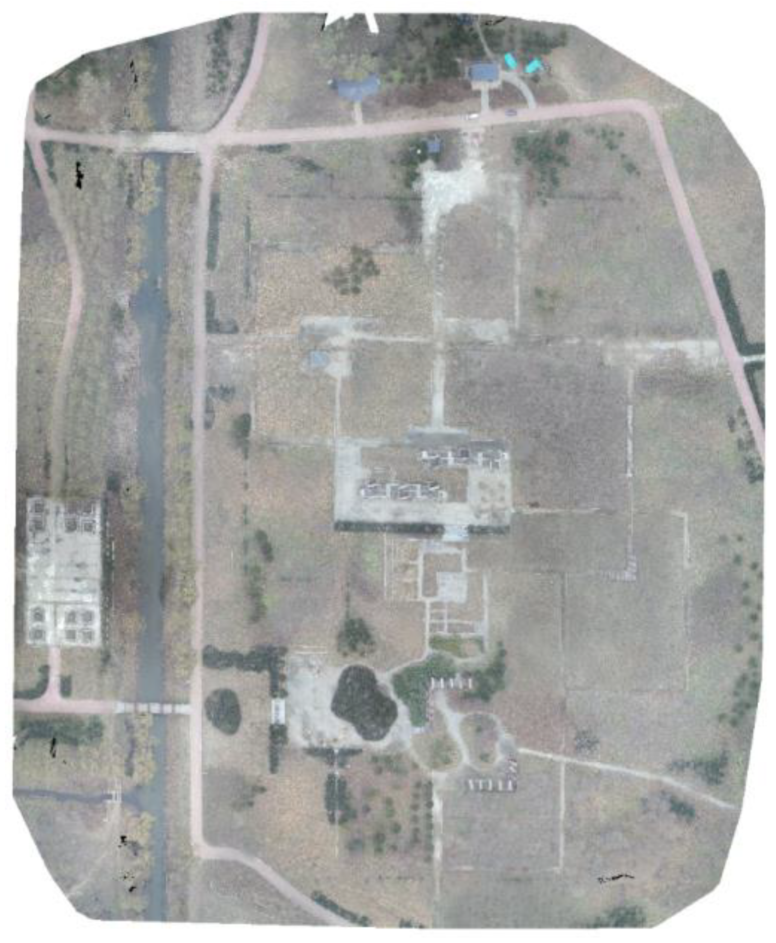
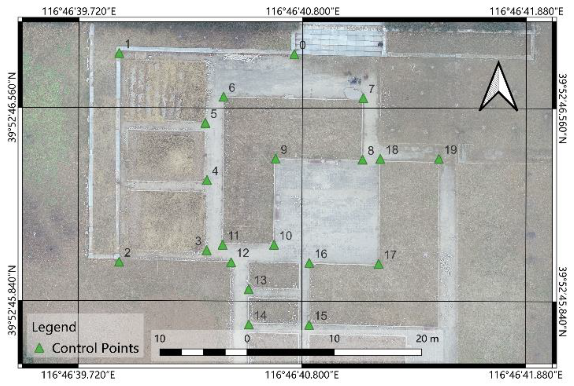
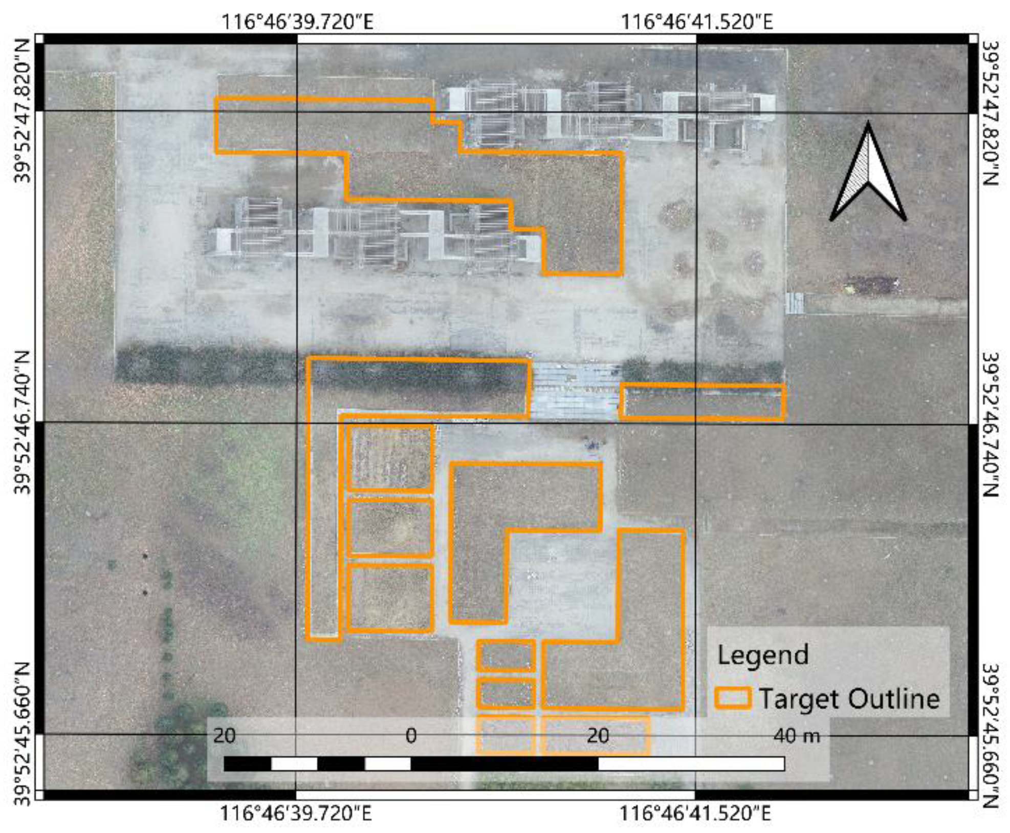
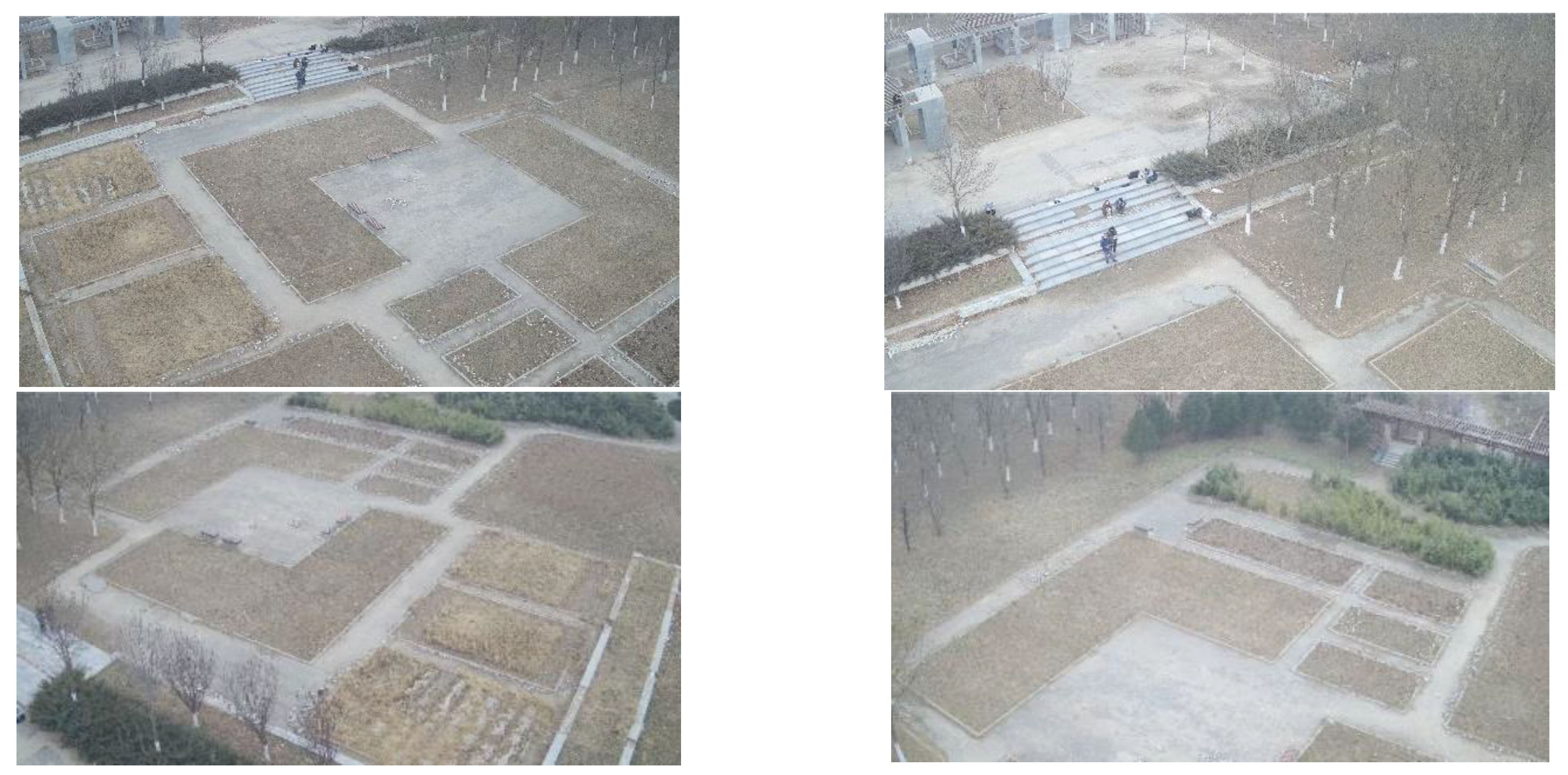
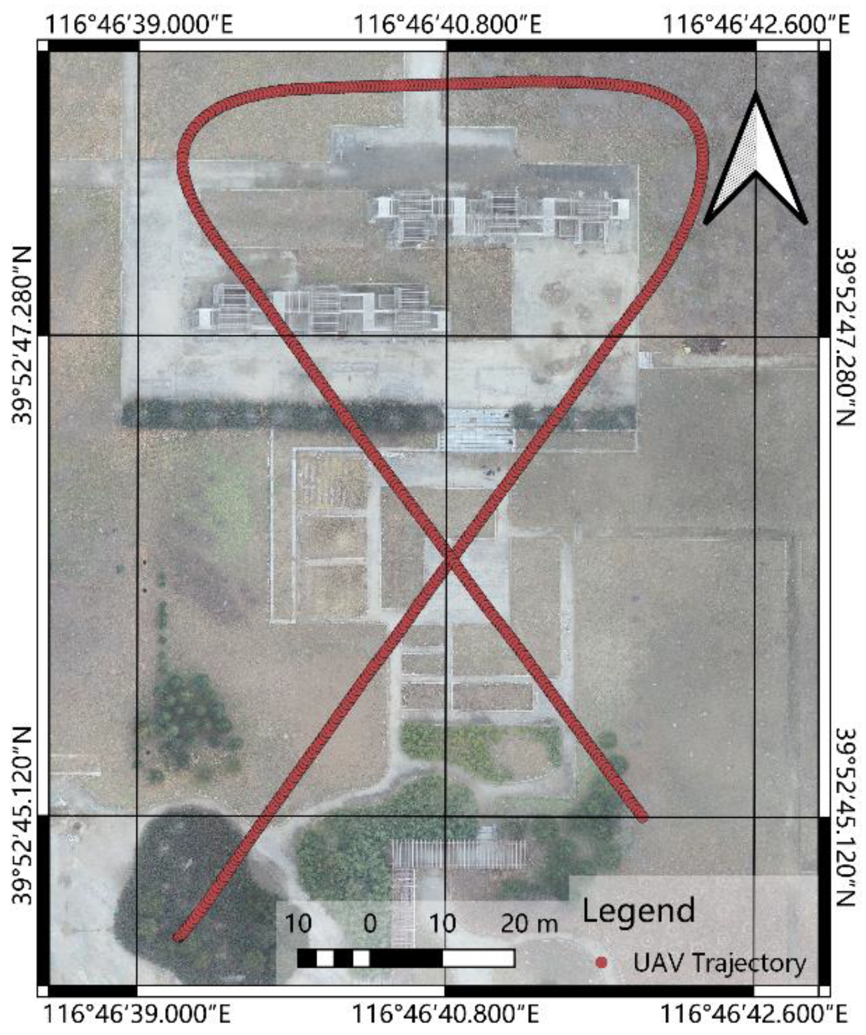
4.2. Experimental Area and Geographic Data Collection

The experimental area for the AR geo-registration of a UAV TIR video was located in Lucheng Medicine Art Park, Tongzhou District, Beijing, China. The terrain of the experimental area is flat, and the ground targets have a large number of distinctive corner points, which makes it easy to select target points for localization. The experimental area is shown in Figure 8.
Visible images of the experimental area were first acquired using a UAV and stitched together using Pix4Dmapper software to obtain the geographic information used for the enhancement of the TIR video. The weather was cloudy and breezy at the time of data acquisition. The UAV flew at an altitude of 80 m with a 75% overlap in the heading and a 75% overlap in the side direction, and the total route length was 4058 m, over which a total of 360 visible images were obtained. The route range is shown in Figure 9, and the ground resolution after Pix4Dmapper stitching was 2.15 cm, as shown in Figure 10.
To ensure the accuracy of the geographic information mapped based on the UAV visible images, ground control points were collected in areas with significant corner point features on-site, as shown in Figure 11.
The control points were evenly distributed in areas with richer corner features, and there were 20 in total. The control points were used to accurately calibrate the stitched images. Because the areas without control points may have significant resampling errors, only those with control points were retained for mapping the vector map in the calibrated visible images. The target area contains several flowerbeds with rich corner point features suitable for identifying and measuring control points. The coordinates of the control points were measured by placing the D-RTK antenna on the location of control points. The horizontal accuracy of the control points is 1 cm + 1 ppm, and the vertical accuracy is 2 cm + 1 ppm [28]. Based on the acquired control points, a cubic polynomial transformation was performed on the stitched image. The average residual of control points in the image was 3.52 pixels.
The vector map obtained by following the outline of the flowerbed features in the target area is shown in Figure 12.

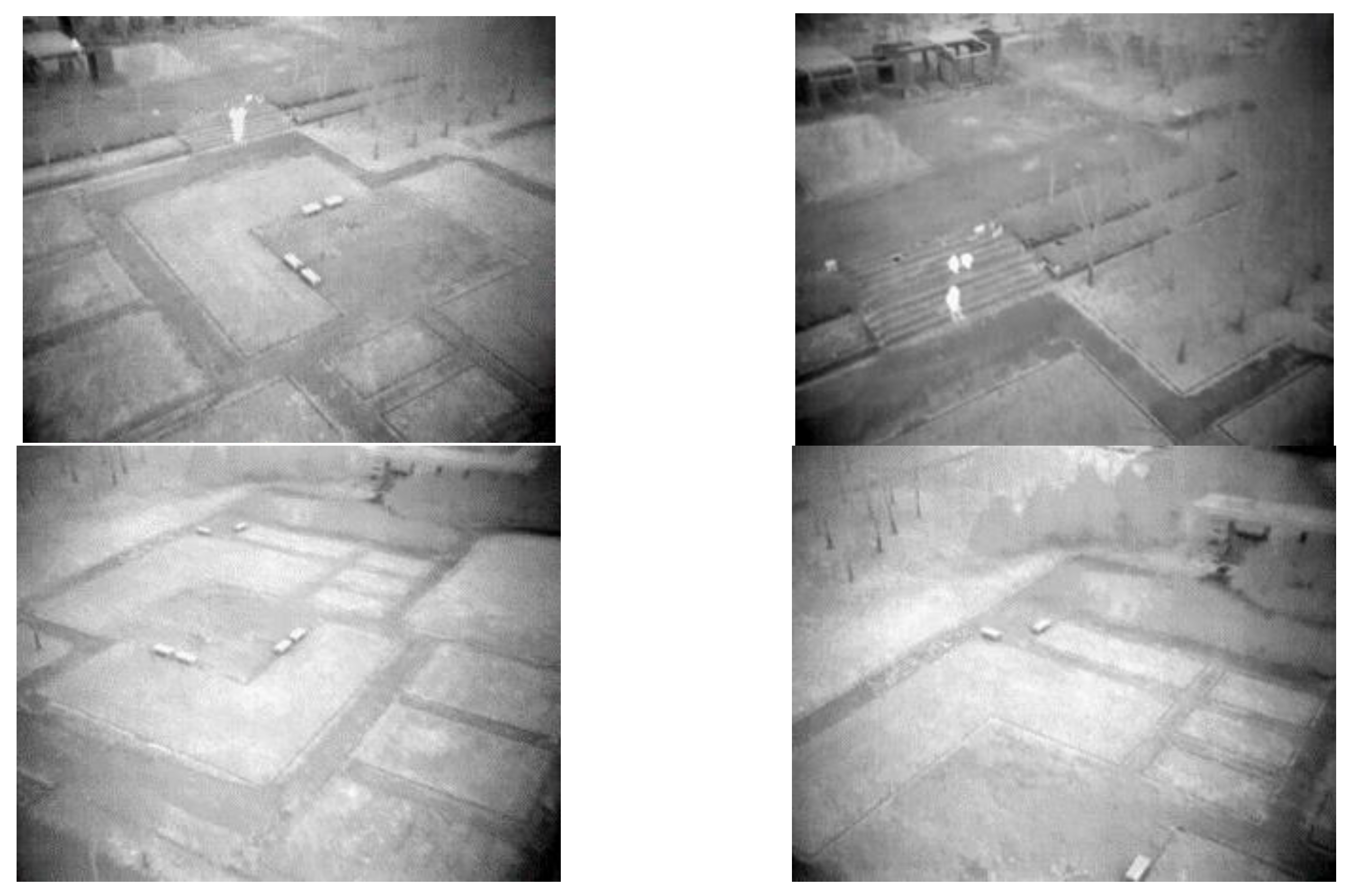
4.3. TIR Video and UAV Flight Data Acquisition

Pre-defined waypoints were adopted for the flight for TIR video and UAV attitude data collection, and the UAV flew autonomously according to the pre-defined waypoints and trajectories. TIR video streams were recorded during the flight, and the necessary information, such as the UAV positioning data, attitude data, acceleration, and angular velocity, were obtained by the onboard computer. The speed of the UAV was 3 m/s, its altitude was 20 m, and the time required to fly the entire route was 107 s.
The TIR and visible light videos are respectively shown in Figure 13 and Figure 14. During the flight, the gimbal was tilted 30° downward relative to the horizontal direction. Due to the tilt of the camera, the ground resolution in the video was not constant; considering the horizontal FOV of the TIR camera is 45° and the horizontal pixel number is 640, the resolution of the image center in the TIR video is about 0.05 m.
Figure 15 presents the RTK trajectory. As the frequency of the RTK recorded data was relatively fixed, the sparsity of the trajectory points corresponds to the airspeed of the UAV.

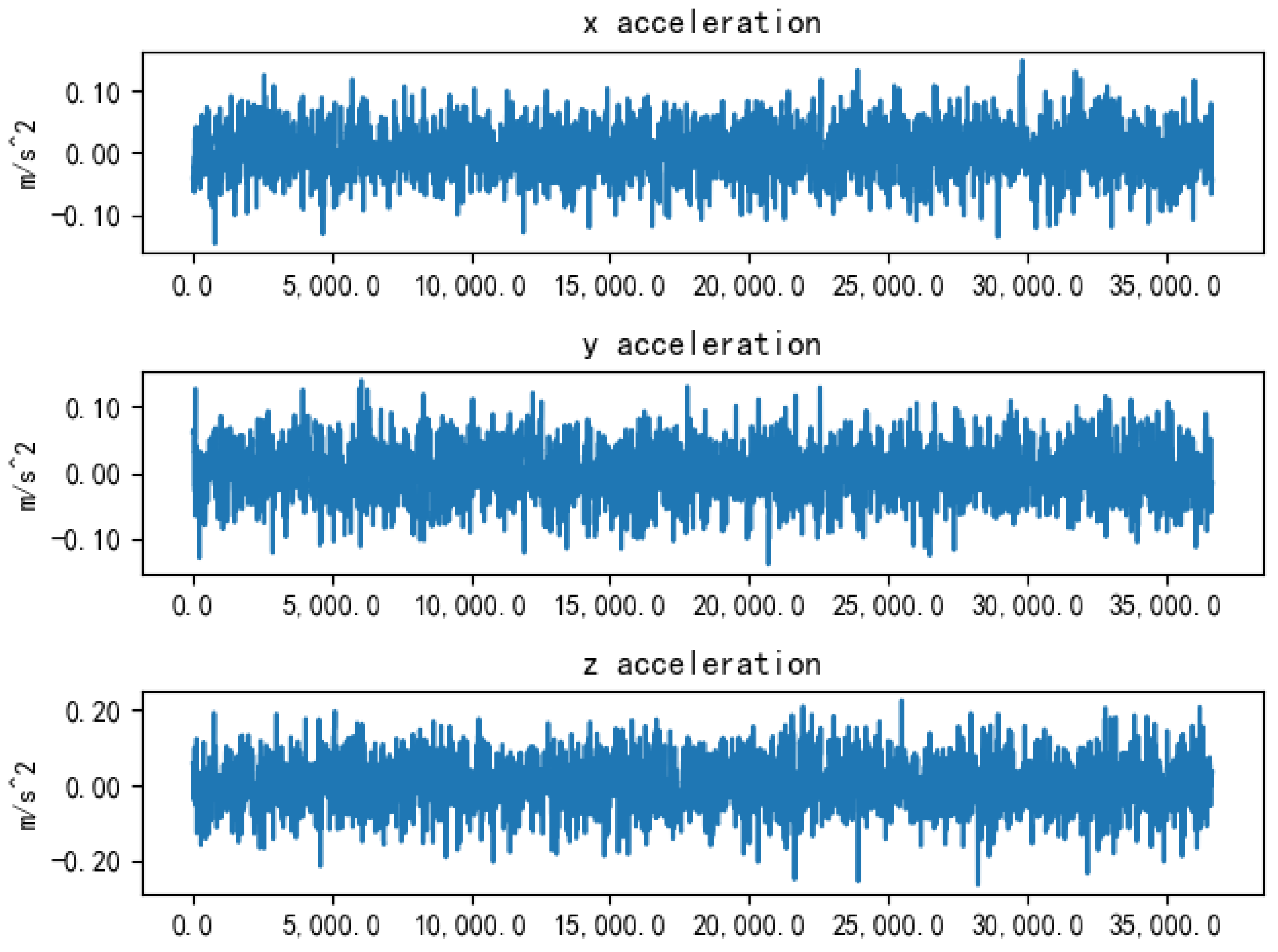
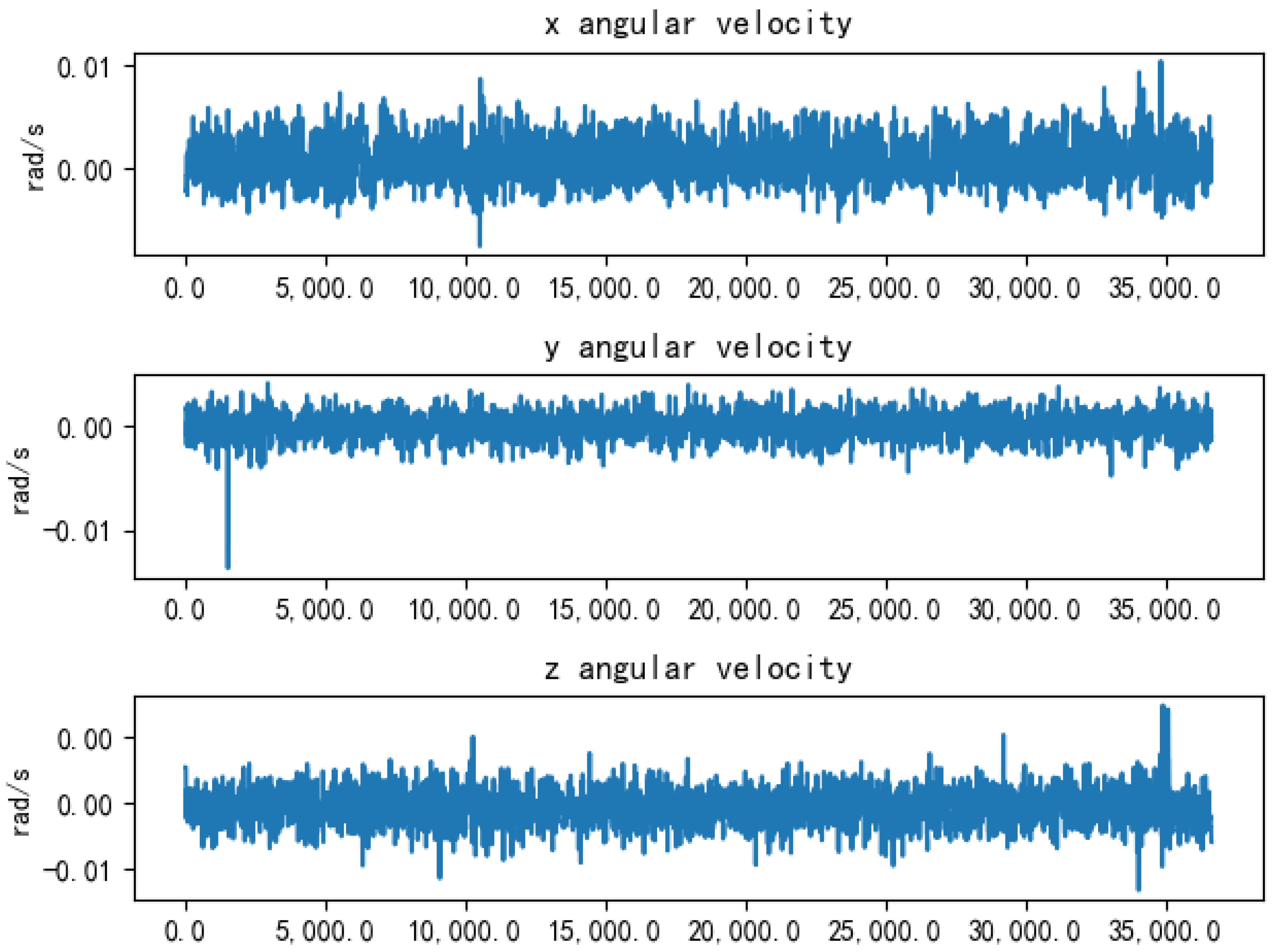
4.4. IMU Error Parameter Acquisition

In the method proposed in Section 3.3, an algorithm based on an improved extended Kalman filter is used to fuse RTK data with other UAV attitude data to improve the accuracy of the UAV attitude measurement. The algorithm requires the error parameters of the UAV flight control mounted sensors to be set in the process of computing. This improves the registration accuracy of the UAV TIR video to a certain extent via high-accuracy RTK positioning and dual-antenna directional measurement data.
The sensor error parameters are calculated using the Allan variance algorithm, a widely used method for modeling the random errors of inertial devices. By analyzing the output results of inertial devices, a series of error characteristics, such as random wandering error and the dynamic error of gyroscopes and accelerometers, can be calculated.
To calculate the error characteristics of the IMU of the M600 platform, the output values of the gyroscope and accelerometer of the stationary M600 UAV were first recorded for a period of 5 h, and the output data are exhibited in Figure 16 and Figure 17.
As shown in Figure 16, the accelerations along the three-axis directions were respectively measured by the UAV sensors under the UAV body coordinate system, where the x-, y-, and z-axes respectively indicate the forward, right, and downward directions of the UAV. It can be seen that the output of the UAV accelerometer still exhibited large fluctuations in the stationary state of the UAV.
As shown in Figure 17, the angular velocity output of the UAV was also found to have large fluctuations. Because the attitude angle of the UAV must be obtained from the angular velocity integration, the angular velocity accuracy of the UAV will have a large impact on the attitude calculation of the UAV.
From Figure 16 and Figure 17, it can be seen that there were large errors in both the acceleration and angular velocity measurements of the UAV. These errors will cause further errors in the UAV position and attitude measurements, which will affect the accuracy of TIR video geo-registration.
The acceleration and angular velocity data output from the UAV IMU after Allan variance calculation are reported in Table 5.

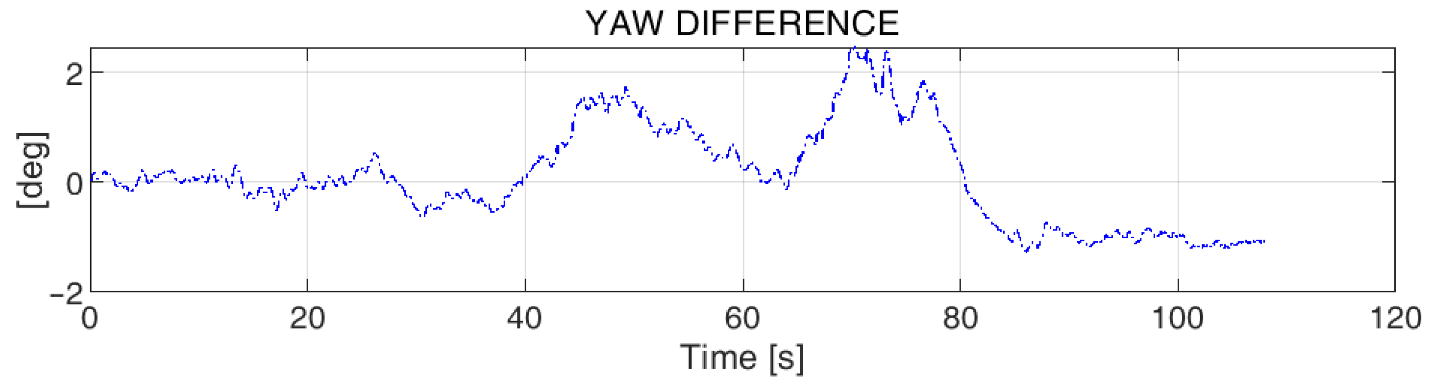
4.5. UAV Attitude Data Enhancement Results

The improved extended Kalman filter algorithm was realized based on an open-source toolbox for processing integrated navigation systems named NaveGo [25,29], and initialized using the parameters reported in Table 5. After initializing the algorithm, the UAV attitude data were calculated by the improved extended Kalman filter algorithm, as exhibited in Figure 18.
As presented in Figure 18, relative to the original values of the UAV three-axis attitude, the UAV three-axis attitude was corrected to different degrees after adding RTK positioning and dual-antenna heading angle data. The correction values of the heading direction are presented in Figure 19. The heading axis data were used to further calculate the camera heading angle, and the result is shown in Figure 20. The corrected camera heading angle could then be used for the high-precision AR geo-registration of the UAV TIR video stream.

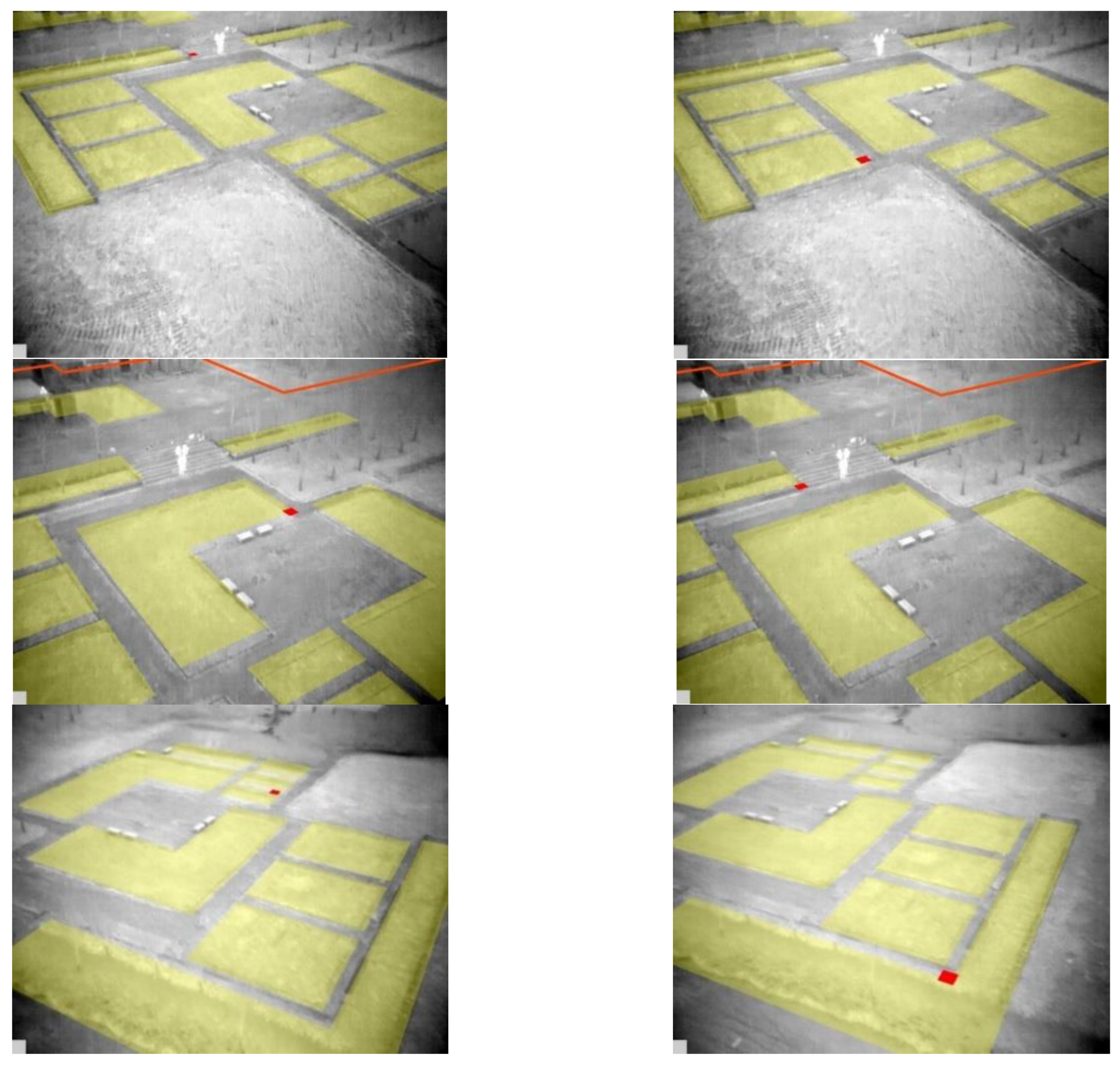
4.6. High-Precision Geo-Registration Results of UAV TIR Video

The camera poses and positions obtained by processing via the improved extended Kalman filter algorithm can be used to register the UAV TIR video. The manufacturer of the video transmitting devices provides a delay value via testing. In this research, the onboard video link has a latency of 50 ms according to the manual of the UAV [30]. This latency may vary during the flight according to the distance between the UAV and the ground station, the radio inference, and other factors. For multi rotor wing UAVs, the working distance will not be too long; thus, this latency from the manual will be suitable in actual operations. The geo-registration of the UAV TIR video was performed according to the method described in the authors’ previous study [14], and some screenshots of the AR video stream obtained after registration are provided in Figure 21.
As shown in Figure 21, the features in the UAV TIR video were not significantly misaligned with the vector map, indicating that the conversion relationship from the world coordinate system to the screen coordinate system can be correctly calculated using the corrected data.

5. Assessment and Discussion

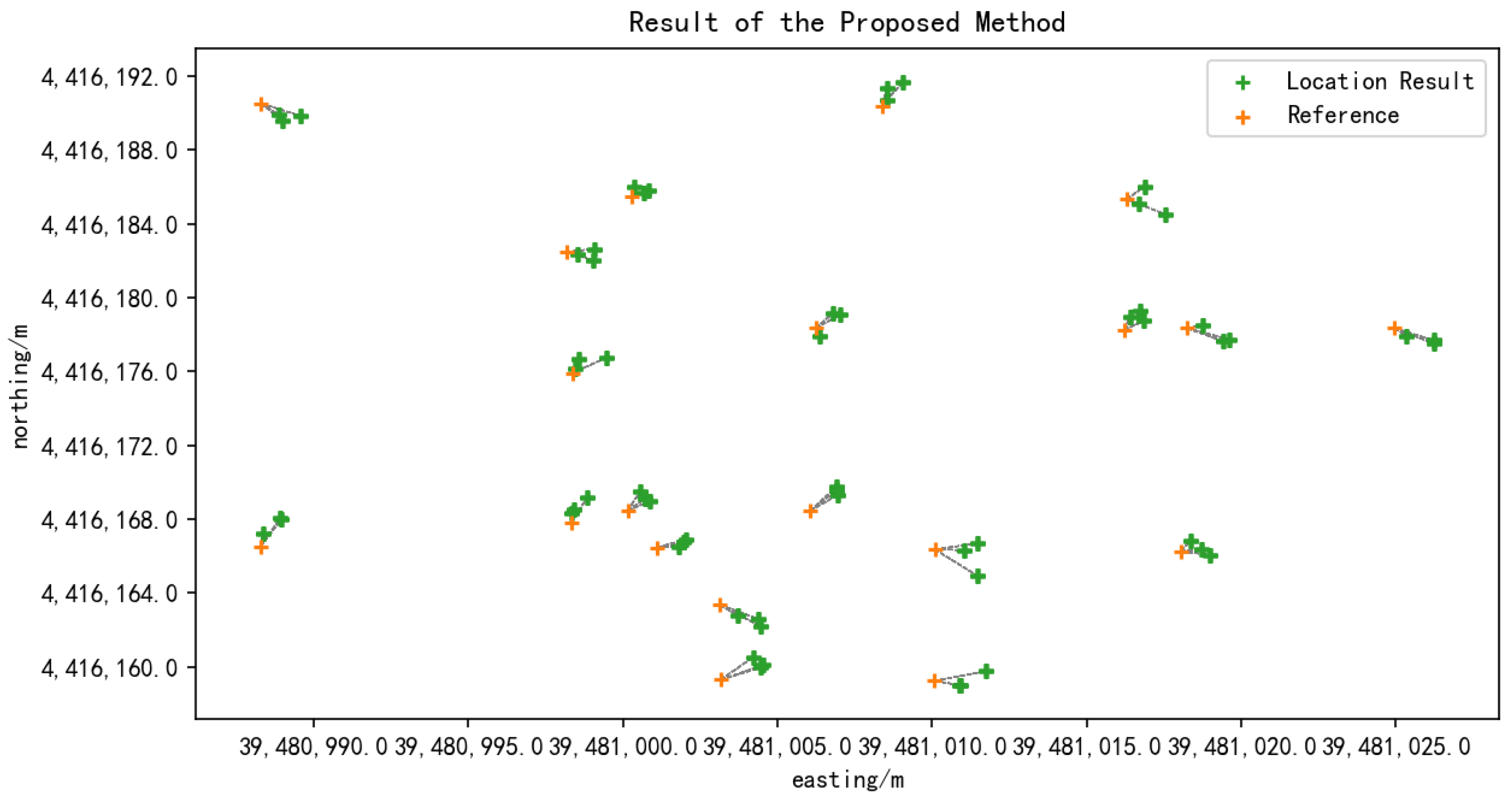
5.1. Geo-Registration Accuracy Assessment

A practical assessment of the registration accuracy can be conducted by locating the ground target in the registered video. A good registration accuracy means that the localization result of the ground target in the registered video should match the actual position of the object to the greatest extent. The process of localizing the ground target is the inverse of the geo-registration algorithm described in the authors’ previous publication [14], i.e., the coordinates of the target on the screen ( u , v ) are known, and the process of finding the coordinates of the ground point in the world coordinate system ( X ,   Y ,   Z ) is defined as:
[ X Y Z 1 ] = M W S 1 [ u v 1 ]
where M W S = M P S M C P M W C is the transformation matrix from the world coordinate system to the screen coordinate system. Equation ( 23 ) represents the ray that connects the lens optical center, the projection plane, and the actual position of the ground target. Intersecting this ray with the terrain means to use known u ,   v , M W S 1 , and making Z = 0 , yields the ground position ( X , Y ) corresponding to the point on the screen. Because the target area in this study is relatively flat, the plane Z = 0 is used as the approximate the terrain of the ground.
The accuracy of the AR geo-registration of the UAV TIR video was evaluated based on the ground control points used in Section 4.3, which are ground targets with significant angular point characteristics, and the positions were accurately measured using differential GPS receivers. During the test, the corresponding points were selected from the geo-registered TIR video, and the ground coordinate values calculated according to Equation ( 23 ) were recorded. Each point was measured three times, and the measurement screen of some of the control points is shown in Figure 22.
For a comparison of the accuracy, the positioning results and the coordinates of the reference point were converted to a plane coordinate system in meters according to Gaussian projection, and the three measurements were used to calculate the RMSE as the positioning error for the point:
e R M S = j = 1 n p o i n t s ( P o s g t P o s j r e s u l t ) 2 n p o i n t s
where P o s g t is the control point location, P o s j r e s u l t is the j th measurement of the ground target in the TIR video, n p o i n t s is the number of measurements at that point, and n p o i n t s = 3 . The measurements are exhibited in Table 6, and to determine the statistical significance of the differences between the test results, a t-test was performed on the three sets of measurements. The p-value results are reported in Table 7.
The data exhibited in Table 6 show that there was a significant improvement in ground point positioning results using both the RTK positioning data and filtered camera heading data. The p-value results presented in Table 7 show that there was a highly significant statistical difference between the data at the 95% confidence level for the three sets of measurements.
According to Figure 23, large and unstable positioning errors occurred when using geo-registering with raw attitude data. A certain pattern was identified in the direction of the positioning error, but the absolute value of the error varied significantly in the same direction. The average RMSE was 3.2149 m, which is less than the theoretically calculated value. Because the average value within the FOV is used when theoretically calculating E r e g C a m P o s i t i o n 3 D and E r e g C a m H e i g h t , the larger error value at the far side of the FOV increases the estimated values of E r e g C a m P o s i t i o n 3 D and E r e g C a m H e i g h t . In the actual measurement, to facilitate the identification of ground target points in the video, the positioning operation of ground target points usually occurs closer to the camera in the FOV, causing the positioning error in the actual measurement to be less than the estimated value.
Figure 24 reveals that after using the RTK localization results, the accuracy of the localization of the ground targets in the videos was improved. Relative to Figure 23, the directions of some of the localization results were different from the standard values, and the errors were significantly reduced with significant directionality. The RMSE was reduced to 2.4630 m. The improvement in the positioning accuracy using RTK positioning data was less than the theoretical prediction in the calculation of the registration error due to the different factors in Table 2, as the error of positioning the ground targets using the original GPS with the camera attitude was less than the theoretically calculated value.
Figure 25 presents the result of the method proposed in the authors’ previous research [14]. It can be seen from the figure that the localization accuracy was improved, but was not quite stable; thus, both excellent and poor results were achieved simultaneously.
Figure 26 exhibits the localization results of geo-registration using the UAV attitude data enhanced by the proposed method. Both the localization accuracy and the distribution of errors were found to be significantly improved. This means that after replacing the original camera heading data with the filtered camera heading data, the geo-registration and target localization accuracy were further improved, and the average RMSE was reduced to 1.0905 m. The reduction in the error was found to be roughly consistent with the theoretical predictions in Section 3.5.

5.2. Evaluation of the Airborne Gimbal Stabilization Effect

As mentioned previously, during the flight of the UAV, the onboard gimbal keeps the camera attitude angle stable in the camera traverse and pitch directions. This causes the onboard camera to follow the fuselage rotation in the heading angle direction. Therefore, it is considered that the camera attitude angle is relatively stable in the pitch and roll directions. The main source of the camera attitude angle error is the heading error. To confirm the stabilization capability of the airborne gimbal in the pitch and roll directions, the stability of the airborne gimbal was evaluated.
As displayed in Figure 27, a checkerboard calibration plate was fixed vertically on a wall, and the onboard camera was pointed at the checkerboard. The airframe was rotated in three directions, namely the pitch, roll, and heading directions, and a video of a certain duration was captured. The recorded video was extracted at 10 fps to obtain a series of still images containing the calibration plate.
The acquired still images were calibrated by the MATLAB Camera Calibration component [30], and the results are presented in Figure 28.
As shown in Figure 28, the attitude change in the calibration plate relative to the camera calculated by the calibration operation was primarily in the heading direction, and there was no obvious change in the pitch and roll directions due to the stabilization of the gimbal. The attitude angle of the calibration plate relative to the camera is exhibited in Figure 29. The attitude angle of the camera relative to the calibration plate calculated from the image containing the calibration plate exhibited a 30° change in the heading direction with random body movement, while there was only a slight fluctuation of about 1° in the pitch and roll axes.
The standard deviation of the attitude angle in each direction is reported in Table 8. The standard deviation of the relative attitude angle between the calibration plate and the camera was less than 1° in both the pitch and roll directions. However, the standard deviation was more significant in the heading direction, reaching 13.8857°, because the camera followed the fuselage movement and the heading angle changed to a greater degree.
The data reported in Table 8 demonstrate that the UAV gimbal can effectively stabilize the camera motion in the pitch and roll directions. The camera pitch and roll data provided by the UAV flight controller can therefore be directly used in AR geo-registration. Furthermore, in the error analysis, the influence of pitch and roll angle errors can be ignored, and focus can be placed on the influence of the camera heading angle errors on geo-registration.

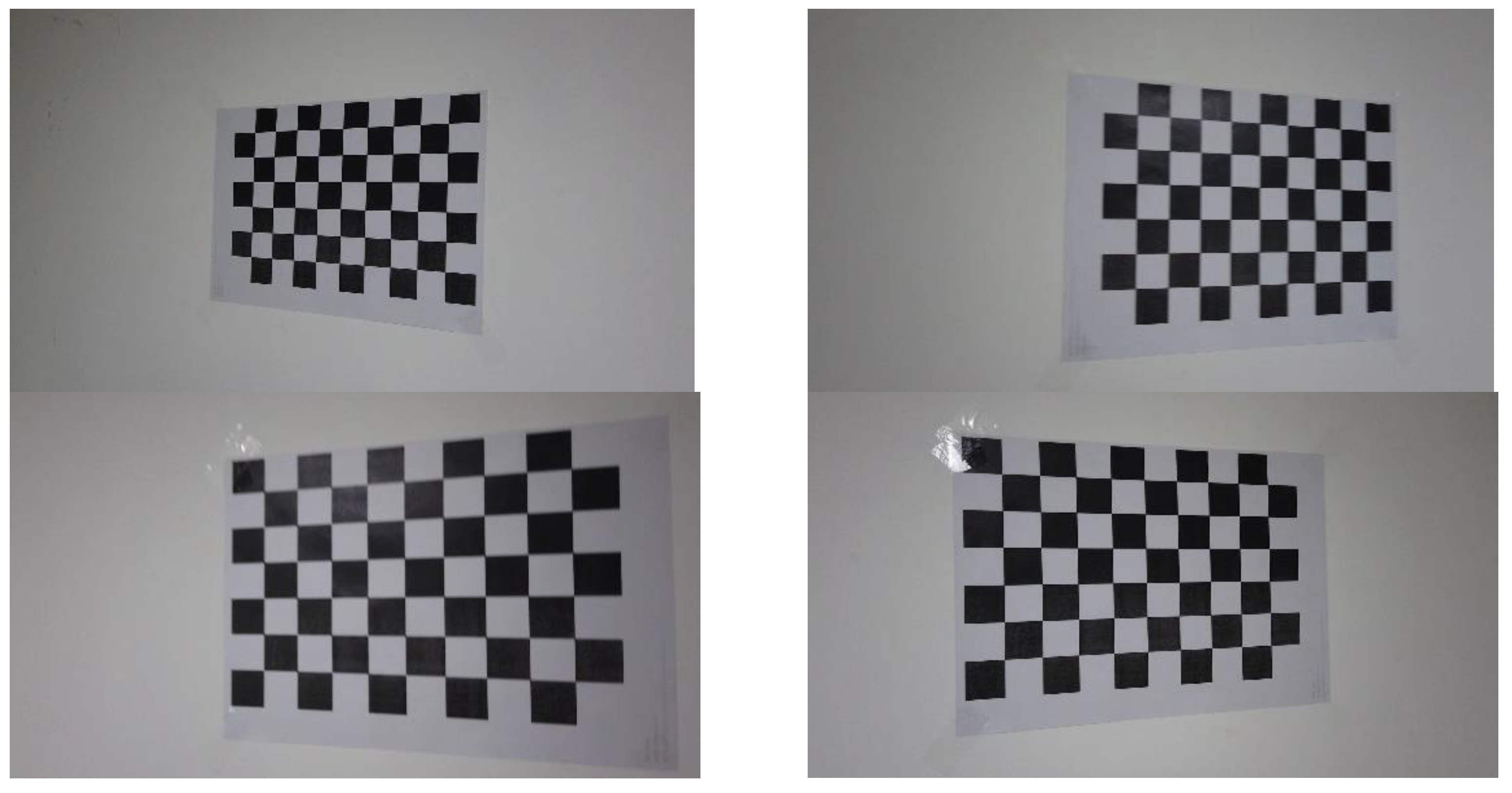
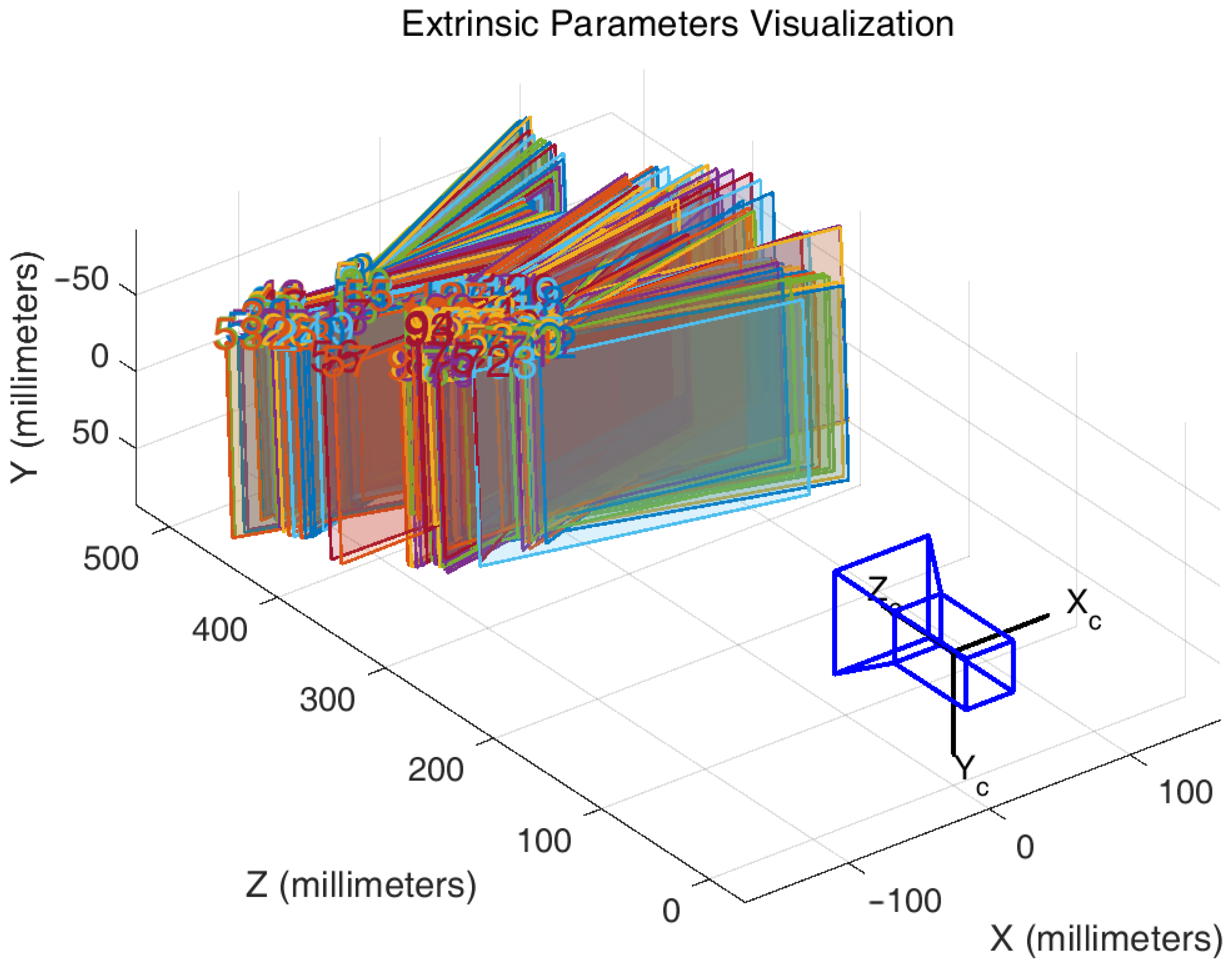
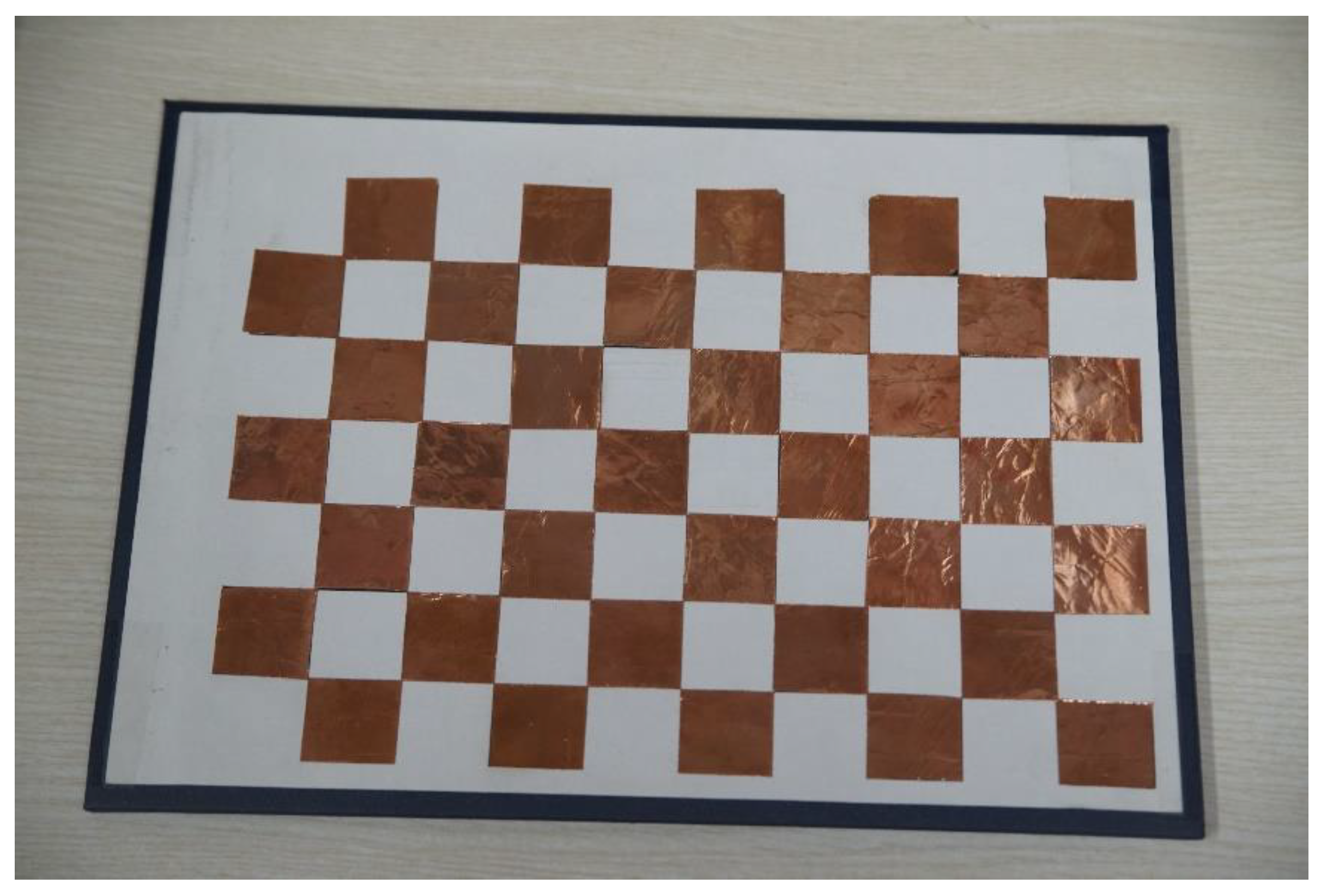
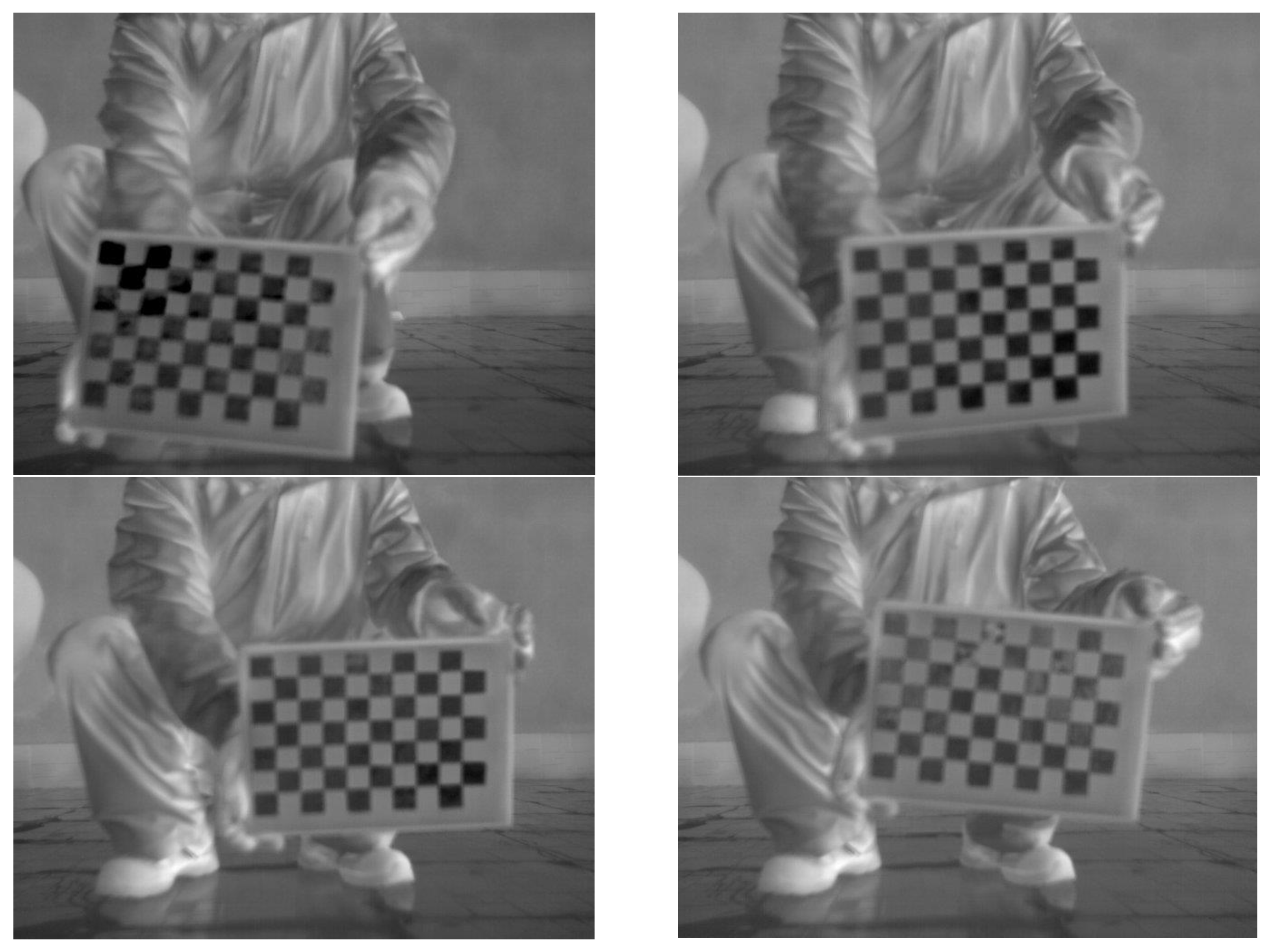
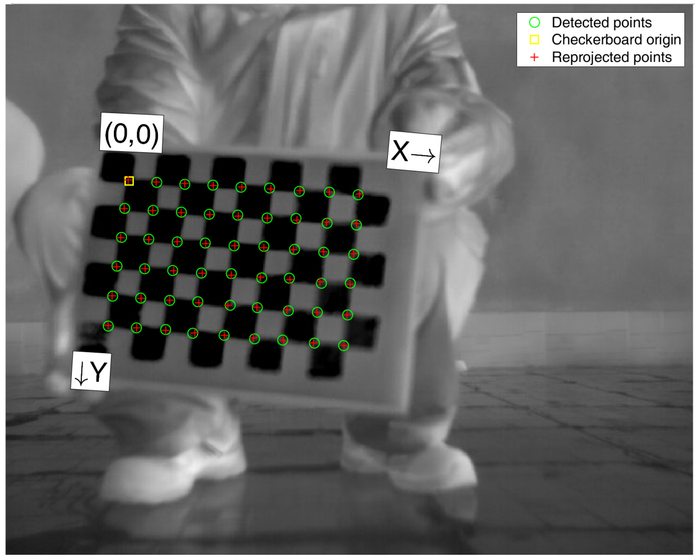
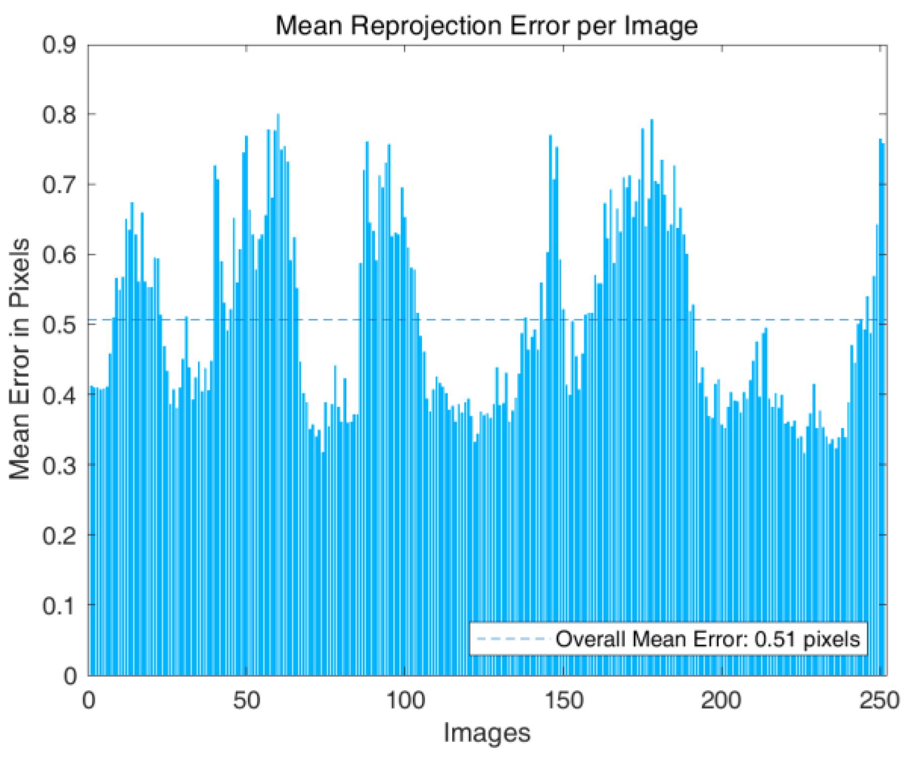
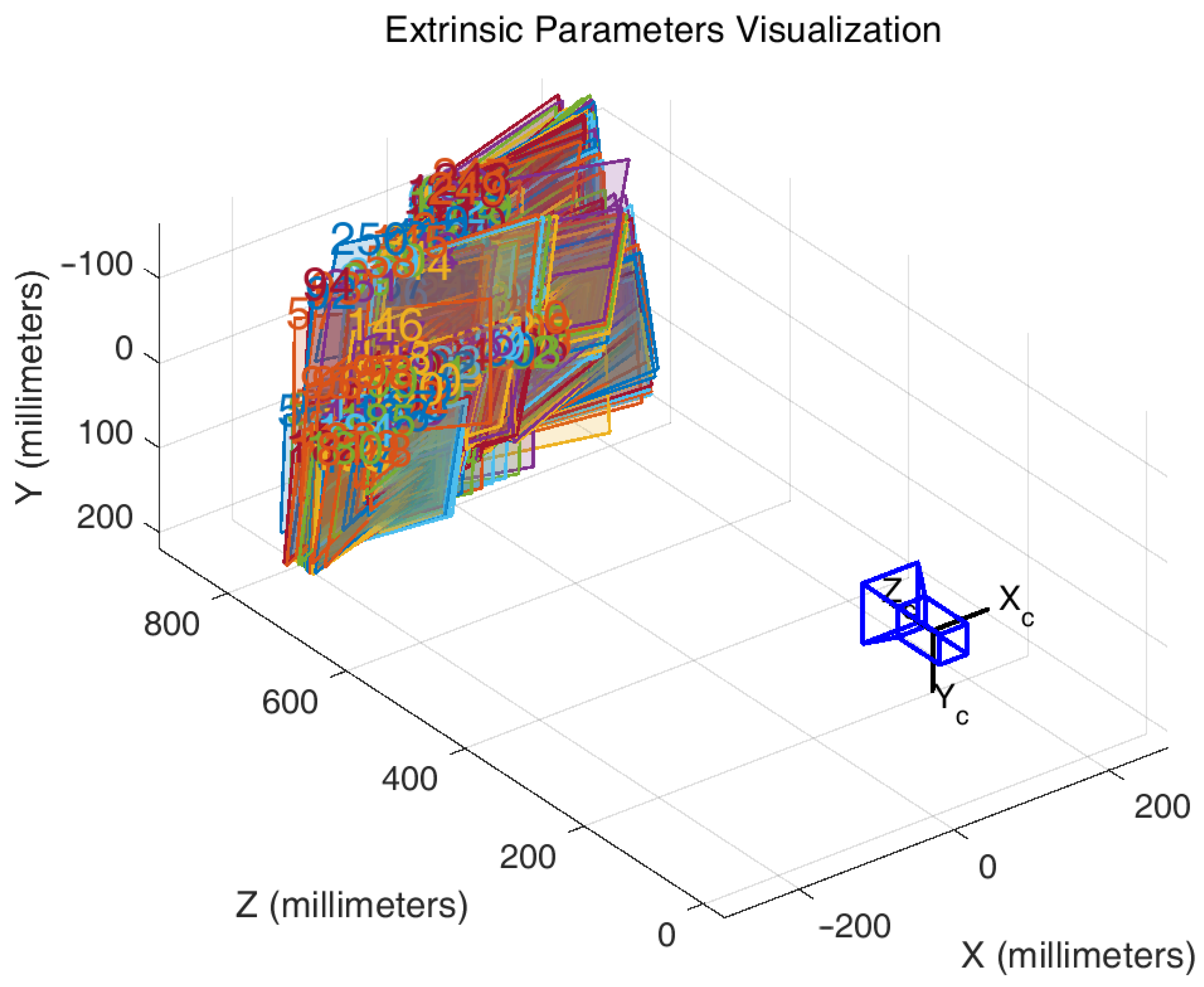
5.3. Assessment and Correction of Lens Distortion

The display of AR information on the screen adheres to the ideal central projection model. Camera lens distortion, which deforms the imaging of the camera, will increase the error of geo-registration. To ensure the accuracy of the geo-registration of TIR videos and the positioning of ground points based on the registration results, the lens error of the TIR camera must be calibrated and corrected. The calibration and correction of the lens error were performed using a checkerboard. However, because TIR cameras image objects based on temperature, a unique checkerboard was required.
As displayed in Figure 30, the black squares on a plain checkerboard were covered with copper foil tape, allowing the board to exhibit the appearance of squares in the TIR image. The TIR images taken during the calibration process are shown in Figure 31.
The captured images were calibrated using the MATLAB Camera Calibration component [31], as shown in Figure 32.
The camera distortion parameters obtained from the calibration are reported in Table 9.
As shown in Figure 33, the average reprojection error of the participating calibration images was about 0.51 pixels, and the maximum reprojection error did not exceed 0.8 pixels; thus, the calibration results were considered to be of high accuracy. As shown in Table 9, the pixel position errors caused by the deviation in the image principal point position in the horizontal and vertical directions were respectively 27.5725 and 3.044 pixels. The relative position of the calibration plate from the calibration calculation is shown in Figure 34. The corrected values of the lens correction for the pixel position in the TIR image can be calculated using the radial aberration and tangential aberration equations, as respectively given by Equations (26) and (27):
{ x 0 = x ( 1 + k 1 r 2 + k 2 r 4 ) y 0 = y ( 1 + k 1 r 2 + k 2 r 4 )
{ x 0 = x + [ 2 p 1 x y + p 2 ( r 2 + 2 x 2 ) ] y 0 = y + [ 2 p 2 x y + p 1 ( r 2 + 2 y 2 ) ]
where ( x 0 , y 0 ) is the pixel position before the aberration correction, and ( x , y ) is the pixel position after the aberration correction. ( x 0 , y 0 ) and ( x , y ) are the normalized pixel coordinates divided by the camera focal length value in pixels. Moreover, r is the distance from the normalized pixel point to the optical center. According to Equations ( 25 ) and ( 26 ), the maximum values of the pixel position error generated by radial aberration in the horizontal and vertical directions were respectively 11.72 and 9.37 pixels, and the maximum values of the pixel position error generated by tangential aberration in the horizontal and vertical directions were respectively 1.59 and 0.73 pixels.
The error parameters in Table 9 were used in further AR registration operations to correct the TIR images for lens distortion, and the corrected results are presented in Figure 35. The corrected results are shown on the right side, and the blank portion of the image boundary area after significant distortion is marked in red.

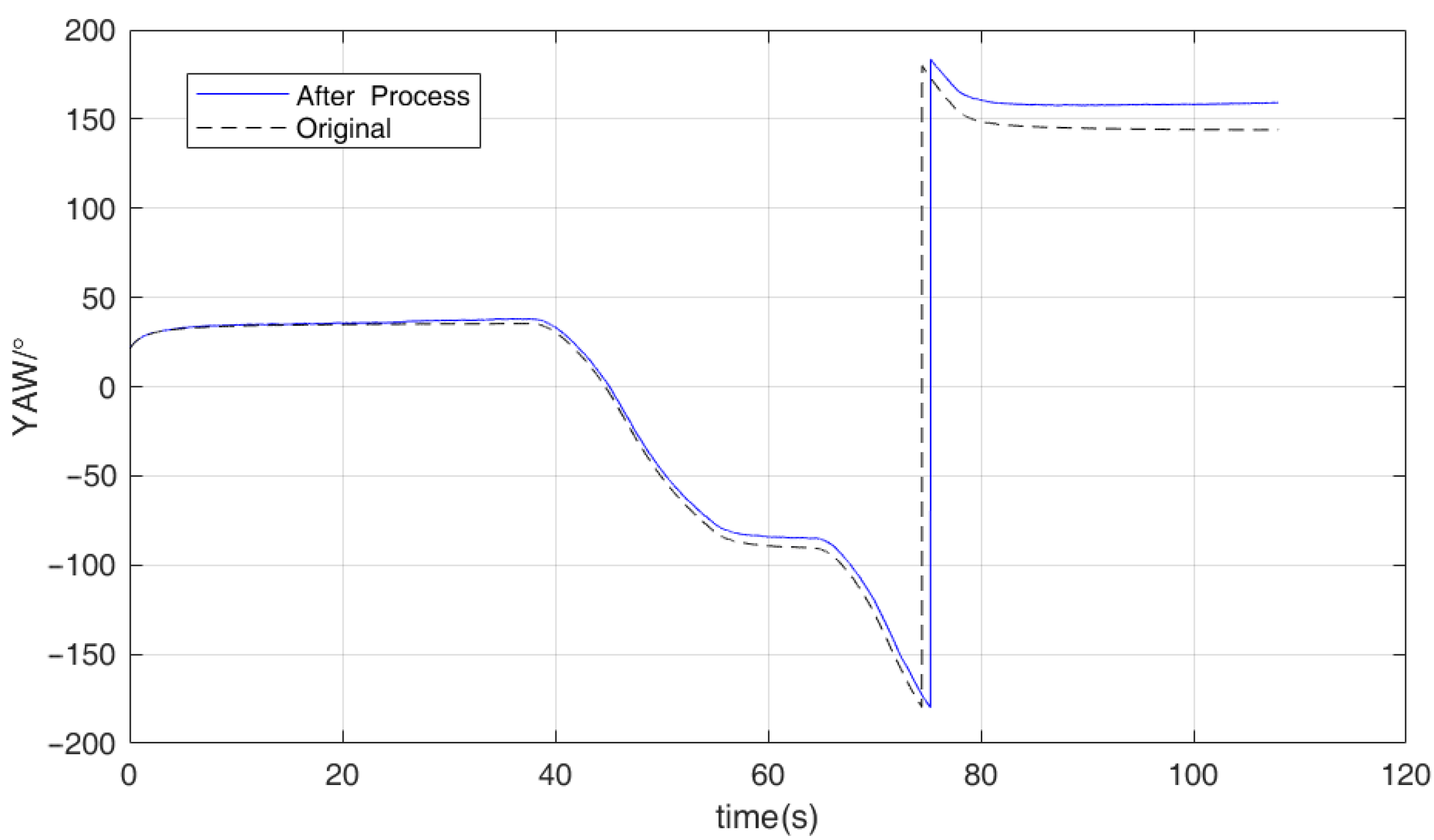
5.4. The Effect of a Sudden Change in the Body Attitude

During the flight, a sudden change such as a wind shear may make the UAV body has a sudden change. We consider this issue in terms of two aspects:
  • As mentioned in Section 3, the input GNSS position has a median filter to deal with a sudden position change in the UAV body.
  • A sudden change means that the effect may have a short impact time. Thus, the error caused by the sudden change may also last for a very short time, which means that the working state of the EKF will quickly return to being steady. In our consideration, this can be tolerated during the process. The registration can quickly return to normal and continue to provide accurate results.

6. Conclusions

This study presented a new geo-registration algorithm in which AR technology was used to superimpose geographic information onto UAV TIR video to enhance the accuracy of geo-registration of UAV TIR images via the use of high-precision RTK fixation on dual-antenna directional data in the context of nighttime emergency rescue and other operations. The traditional extended Kalman filter algorithm was optimized to achieve the high accuracy of RTK, and the RTK positioning results were considered to be plausible values to be updated in each cycle. The improved extended Kalman filter algorithm can accept the directional results of dual-antenna RTK as the measured values for input.
For the experimental validation of the proposed algorithm, TIR video of the experimental area were augmented with the proposed algorithm using the existing vector maps of the experimental area and the real-time flight status data of the UAV. The positions of the ground targets in the video that had been geo-registered with AR were determined, and then compared with the actual positions of the targets. Compared with the use of the positioning and camera attitude data provided by the UAV flight control, the registration error of the UAV TIR video stream was found to be reduced from 3.22 to 2.46 m using RTK positioning, and the geographic error was further reduced to 1.09 m using the heading data calculated by the improved extended Kalman filter algorithm. Thus, the registration error was reduced by a total of 66.15%, and the geo-registration accuracy of the UAV TIR video stream was significantly improved.
The experimental results proved that the proposed augmentation of UAV attitude data using high-precision RTK positions and dual-antenna heading data via an improved extended Kalman filter algorithm can effectively improve the accuracy of the attitude data of low-cost UAVs, based on which the high-precision geo-registration of UAV TIR video streams can be achieved. By performing the high-precision AR geo-registration of UAV TIR video streams, the effect of the application of AR technology to low-cost UAV TIR video streams can be effectively enhanced to provide better geographic information support for emergency rescue operations at night.

Author Contributions

Conceptualization, X.R. and M.S.; methodology, X.R.; data acquisition, L.L., X.W. and H.Z.; writing—original draft preparation, X.R.; writing—review and editing, M.S. and X.Z.; supervision, M.S.; project administration, M.S.; funding acquisition, M.S. All authors have read and agreed to the published version of the manuscript.

Funding

This research was funded by the Department of Sciences and Technology of the Xinjiang Production and Construction Corps, China, grant number 2017DB005, and in part by the High-Performance Computing Platform of Peking University.

Data Availability Statement

Not applicable.

Acknowledgments

We would like to thank anonymous reviewers and editor in chief for their constructive comments, which greatly improved the quality of our manuscript. And special thanks to the author of NaveGo, Rodrigo Gonzalez of the National University of Technology, in Mendoza, Argentina, for helping us for realizing our algorithm.

Conflicts of Interest

The authors declare no conflict of interest. The funders had no role in the design of the study; in the collection, analyses, or interpretation of data; in the writing of the manuscript, or in the decision to publish the results.

References

  1. Zhang, X.; Han, Y.; Hao, D.; Lv, Z. ARGIS-based outdoor underground pipeline information system. J. Vis. Commun. Image Represent. 2016, 40, 779–790. [Google Scholar] [CrossRef]
  2. Agrawal, A.; Cleland-Huang, J. RescueAR: Augmented reality supported collaboration for UAV driven emergency response systems. arXiv 2021, arXiv:2110.00180. Available online: https://arxiv.org/abs/2110.00180 (accessed on 16 March 2022).
  3. Ribeiro, R.; Ramos, J.; Safadinho, D.; Reis, A.; Rabadão, C.; Barroso, J.; Pereira, A. Web AR solution for UAV pilot training and usability testing. Sensors 2021, 21, 1456. [Google Scholar] [CrossRef] [PubMed]
  4. Misse, E.S.; Villacrés, S.A.; Velasco, P.M.; Andaluz, V.H. Augmented reality system for the assistance of unmanned aerial vehicles. In Proceedings of the 2020 15th Iberian Conference on Information Systems and Technologies (CISTI), Seville, Spain, 24–27 June 2020; pp. 1–6. [Google Scholar]
  5. Jill, L.D.; Justin, R.; Nathan, R.; Michael, A.G. Comparing situation awareness for two unmanned aerial vehicle human interface approaches. In Proceedings of the IEEE International Workshop on Safety, Security and Rescue Robotics (SSRR), Undefined, 22–24 August 2006. [Google Scholar]
  6. Foyle, D.C.; Andre, A.D.; Hooey, B.L. Situation awareness in an augmented reality cockpit: Design, viewpoints and cognitive glue. In Proceedings of the 11th International Conference on Human Computer Interaction, Las Vegas, NV, USA, 22–27 July 2005; pp. 3–9. [Google Scholar]
  7. Sadeghi-Niaraki, A.; Choi, S.-M. A survey of marker-less tracking and registration techniques for health & Environmental applications to augmented reality and ubiquitous geospatial Information systems. Sensors 2020, 20, 2997. [Google Scholar]
  8. Liu, W.; Wang, C.; Zang, Y.; Lai, S.H.; Weng, D.; Bian, X.; Lin, X.; Shen, X.; Li, J. Ground camera images and UAV 3D model registration for outdoor augmented reality. In Proceedings of the 2019 IEEE Conference on Virtual Reality and 3D User Interfaces (VR), Osaka, Japan, 23–27 March 2019; pp. 1050–1051. [Google Scholar]
  9. Hiroyuki, H. AR-marker/IMU hybrid navigation system for tether-powered UAV. J. Robot. Mechatron. 2018, 30, 76–85. [Google Scholar]
  10. Colleu, T.; Sourimant, G.; Morin, L. Automatic initialization for the registration of GIS and video data. In Proceedings of the 2008 3DTV Conference: The True Vision-Capture, Transmission and Display of 3D Video, Istanbul, Turkey, 28–30 May 2008; pp. 49–52. [Google Scholar]
  11. Ho, C.C.; Ho, M.C.; Chang, C.Y. Markerless indoor/outdoor augmented reality navigation device based on ORB-visual-odometry positioning estimation and wall-floor-boundary image registration. In Proceedings of the 2019 Twelfth International Conference on Ubi-Media Computing (Ubi-Media), Bali, Indonesia, 5–8 August 2019; pp. 199–204. [Google Scholar]
  12. Li, S.; Cai, H.; Kamat, V.R. Uncertainty-aware geospatial system for mapping and visualizing underground utilities. Autom. Constr. 2015, 53, 105–119. [Google Scholar] [CrossRef]
  13. Huang, W.; Sun, M.; Li, S. A 3D GIS-based interactive registration mechanism for outdoor augmented reality system. Expert Syst. Appl. 2016, 55, 48–58. [Google Scholar] [CrossRef]
  14. Ren, X.; Sun, M.; Jiang, C.; Liu, L.; Huang, W. An augmented reality Geo-registration method for ground target localization from a low-cost UAV platform. Sensors 2018, 18, 3739. [Google Scholar] [CrossRef] [PubMed] [Green Version]
  15. Stilla, U.; Kolecki, J.; Hoegner, L. Texture mapping of 3d building models with oblique direct geo-referenced airborne IR image sequences. In Proceedings of the ISPRS Workshop: High-Resolution Earth Imaging for Geospatial Information, Hannover, Germany, 2–5 June 2009; pp. 4–7. [Google Scholar]
  16. Angelino, C.V.; Baraniello, V.R.; Cicala, L. UAV position and attitude estimation using IMU, GNSS and camera. In Proceedings of the 2012 15th International Conference on Information Fusion, Singapore, 9–12 July 2012; pp. 735–742. [Google Scholar]
  17. Chen, J.; Cao, R.; Wang, Y. Sensor-Aware Recognition and Tracking for Wide-Area Augmented Reality on Mobile Phones. Sensors 2015, 15, 31092–31107. [Google Scholar] [CrossRef] [PubMed] [Green Version]
  18. Liu, W.; Lai, B.; Wang, C.; Bian, X.; Yang, W.; Xia, Y.; Lin, X.; Lai, S.; Weng, D.; Li, J. Learning to match 2D images and 3D LiDAR point clouds for outdoor augmented reality. In Proceedings of the 2020 IEEE Conference on Virtual Reality and 3D User Interfaces Abstracts and Workshops (VRW), Atlanta, GA, USA, 22–26 March 2020; pp. 654–655. [Google Scholar]
  19. Nagy, B. A New method of improving the azimuth in mountainous terrain by skyline matching. PFG J. Photogramm. Remote Sens. Geoinf. Sci. 2020, 88, 121–131. [Google Scholar] [CrossRef] [Green Version]
  20. Schneider, J.; Eling, C.; Klingbeil, L.; Kuhlmann, H.; Förstner, W.; Stachniss, C. Fast and effective online pose estimation and mapping for UAVs. In Proceedings of the 2016 IEEE International Conference on Robotics and Automation (ICRA), Stockholm, Sweden, 16–21 May 2016; pp. 4784–4791. [Google Scholar]
  21. Nakata, Y.; Hayamizu, M.; Koshimizu, K.i.; Takeuchi, F.; Masuto, E.; Sato, H. Accuracy assessment of topographic measurements and monitoring of topographic changes using RTK-UAV in landslide area caused by 2018 Hokkaido Eastern Iburi EarthquakeRTK-UAV. Landsc. Ecol. Manag. 2020, 25, 43–52. [Google Scholar] [CrossRef]
  22. Štroner, M.; Urban, R.; Seidl, J.; Reindl, T.; Brouček, J. Photogrammetry using UAV-mounted GNSS RTK: Georeferencing strategies without GCPs. Remote Sens. 2021, 13, 1336. [Google Scholar] [CrossRef]
  23. Svedin, J.; Bernland, A.; Gustafsson, A. Small UAV-based high resolution SAR using low-cost radar, GNSS/RTK and IMU sensors. In Proceedings of the 2020 17th European Radar Conference (EuRAD), Utrecht, The Netherlands, 10–15 January 2021; pp. 186–189. [Google Scholar]
  24. Groves, P.D. Principles of GNSS, Inertial, and Multisensor Integrated Navigation Systems; Artech House: Norfolk County, MA, USA, 2013. [Google Scholar]
  25. Gonzalez, R.; Giribet, J.I.; Patino, H.D. NaveGo: A simulation framework for low-cost integrated navigation systems. Control Eng. Appl. Inform. 2015, 17, 110–120. [Google Scholar]
  26. DJI. DJI Matrice 600 Pro-DJI. Available online: https://www.dji.com/matrice600-pro (accessed on 16 March 2022).
  27. DJI. Zenmuse XT2-DJI. Available online: https://www.dji.com/zenmuse-xt2 (accessed on 16 March 2022).
  28. DJI. D-RTK GNSS-Specs-DJI. Available online: https://www.dji.com/d-rtk/info#specs (accessed on 10 September 2021).
  29. Gonzalez, R.; Dabove, P. Performance assessment of an ultra low-cost inertial measurement unit for GROUND vehicle navigation. Sensors 2019, 19, 3865. [Google Scholar] [CrossRef] [PubMed] [Green Version]
  30. DJI. DJI Lightbridge 2-Professional Quality Live Streaming From the Sky. 2018. Available online: https://www.dji.com/cn/downloads/products/lightbridge-2 (accessed on 16 March 2022).
  31. MathWorks. Computer Vision Toolbox-MATLAB & Simulink. Available online: https://www.mathworks.cn/products/computer-vision.html#camera-calibration (accessed on 10 September 2021).
Figure 1. The workflow of the extended Kalman filter algorithm.
Remotesensing 14 02205 g001
Figure 2. The workflow of the improved extended Kalman filter algorithm.
Remotesensing 14 02205 g002
Figure 3. The measurement of ground points in a TIR image.
Remotesensing 14 02205 g003
Figure 4. The distribution of registration errors caused by camera height errors.
Remotesensing 14 02205 g004
Figure 5. The distribution of registration errors caused by camera heading errors.
Remotesensing 14 02205 g005
Figure 6. The DJI M600 UAV with a dual-antenna D-RTK kit installed.
Remotesensing 14 02205 g006
Figure 7. The differential ground station of the D-RTK suite.
Remotesensing 14 02205 g007
Figure 8. The orthophoto of the experimental area.
Remotesensing 14 02205 g008
Figure 9. Route planning for the acquisition of visible images.
Remotesensing 14 02205 g009
Figure 10. The Pix4Dmapper stitching results.
Remotesensing 14 02205 g010
Figure 11. The distribution of control points.
Remotesensing 14 02205 g011
Figure 12. The vector data extraction results for the target area.
Remotesensing 14 02205 g012
Figure 13. Video frames in the TIR video.
Remotesensing 14 02205 g013
Figure 14. Video frames in the RGB video.
Remotesensing 14 02205 g014
Figure 15. The RTK track recording.
Remotesensing 14 02205 g015
Figure 16. The results of the three-axis acceleration output of the M600 UAV at rest.
Remotesensing 14 02205 g016
Figure 17. The results of the three-axis angular velocity output of the M600 UAV at rest.
Remotesensing 14 02205 g017
Figure 18. The UAV attitude data after processing by the improved extended Kalman filter algorithm.
Remotesensing 14 02205 g018
Figure 19. The corrected values of the airframe heading angle.
Remotesensing 14 02205 g019
Figure 20. The comparison of the camera heading angle before and after correction.
Remotesensing 14 02205 g020
Figure 21. The geo-registration results for the UAV TIR video.
Remotesensing 14 02205 g021
Figure 22. The measurement of ground points in the TIR video; the red squares indicate the results of ground point positioning.
Remotesensing 14 02205 g022
Figure 23. The comparison of the positioning results with the control points using raw attitude data.
Remotesensing 14 02205 g023
Figure 24. The comparison of the positioning results with the control points using raw attitude data and RTK data.
Remotesensing 14 02205 g024
Figure 25. The positioning results obtained using the method described in the authors’ previous work [14].
Remotesensing 14 02205 g025
Figure 26. The positioning results for geo-registration using filtered pose data.
Remotesensing 14 02205 g026
Figure 27. The fixed calibration plate.
Remotesensing 14 02205 g027
Figure 28. The calibration for obtaining the position of the calibration plate relative to the camera.
Remotesensing 14 02205 g028
Figure 29. The change in the attitude angle of the calibration plate with respect to the camera.
Remotesensing 14 02205 g029
Figure 30. The checkerboard for calibrating TIR cameras.
Remotesensing 14 02205 g030
Figure 31. TIR images taken during the calibration process.
Remotesensing 14 02205 g031
Figure 32. Checkerboard corner points detected during calibration.
Remotesensing 14 02205 g032
Figure 33. The reprojection error of the participating calibration images.
Remotesensing 14 02205 g033
Figure 34. The relative position of the calibration plate from the calibration calculation.
Remotesensing 14 02205 g034
Figure 35. The calibration results of TIR images, the change after the calibration is marked by the red frame.
Remotesensing 14 02205 g035
Table 1. Measurement results of root mean square error of each measurement.
Numerical Name E X c a m E Y c a m E h c a m E β
Numerical results1.2846 m0.9342 m2.8017 m1.7972°
Table 2. Calculation results of registration errors due to different factors.
Numerical Name || E r e g C a m P o s i t i o n || || E r e g C a m H e i g h t || || E r e g C a m P o s i t i o n 3 D || || E r e g C a m Y a w ||
Numerical results1.5884 m5.6036 m5.8243 m1.2497 m
Table 3. The parameters of the DJI M600 drone.
ParameterValue
Diagonal Wheelbase1133 mm
Weight (with six TB47S batteries)9.5 kg
Max Takeoff Weight Recommended15.5 kg
Hovering Accuracy (P-GPS)Vertical: ±0.5 m,
Horizontal: ±1.5 m
Max Angular VelocityPitch: 300°/s,
Yaw: 150°/s
Max Pitch Angle25°
Max Ascent Speed5 m/s
Max Descent Speed3 m/s
Hovering Time (with six TB47S batteries)No payload: 32 min,
6 kg payload: 16 min
Flight Control SystemA3 Pro
Operating Temperature−10 °C to 40 °C
Table 4. The parameters of the Zenmuse XT2 TIR camera [27].
ParameterValue
Thermal ImagerUncooled VOx Microbolometer
FPA/Digital Video Display Formats640 × 512
Spectral Band7.5–13.5 μm
Field of View45° × 37°
Exportable Frame Rates<9 Hz
Sensitivity (NETD)<50 mk @ f/1.0
Scene Range (High Gain)−25 °C to 135 °C
Scene Range (Low Gain)−40 °C to 550 °C
Table 5. The sensor error parameters obtained using Allan variance calculation.
Parameter Namex-Axisy-Axisz-Axis
Angular Random Walk ( × 10 4   rad / s )1.68281.96011.6542
Speed Random Walk ( × 10 2   m / s ) 1.29171.29961.2921
Gyro Dynamic Bias ( × 10 6   rad / s )1.528937.0102.2793
Acceleration Meter Dynamic Bias ( × 10 3   m / s 2 )6.05462.85617.9284
Gyro Correlation Cycle70001009000
Acceleration Meter Correlation Cycle2060010,000
Table 6. The comparison of the positioning error of geo-registration using raw attitude data and filtered data.
Data
Number
Original GPS
and Original Attitude (m)
RTK GPS and Original Attitude (m)Our Previous Method (m)The Proposed Method (m)
14.152.861.371.02
24.843.742.381.17
33.183.592.001.40
42.932.451.320.95
51.922.671.400.93
62.372.781.530.80
72.962.991.550.55
83.833.111.341.06
91.932.012.030.93
103.301.901.670.87
112.702.271.231.39
122.772.581.240.95
133.461.581.610.87
142.821.581.351.41
152.421.861.371.56
164.032.031.351.23
174.322.921.301.52
182.622.171.200.77
193.901.931.461.20
203.842.261.221.25
average3.212.461.501.09
Table 7. The p-value results of the t-test between each measurement.
Original GPS
and Original Attitude
RTK GPS and Original AttitudeOur Previous MethodThe Proposed Method
Original GPS
and Original Attitude
-0.0008--
RTK GPS and Original Attitude0.0008-0.00010.0001
Our Previous Method-0.0001-0.0005
The Proposed Method-0.00010.0005-
Table 8. The standard deviation of the attitude angle in each direction obtained by calibration.
DirectionPitchYawRoll
std (°)0.483913.88570.2704
Table 9. The aberration parameters of the TIR camera obtained by calibration.
Parameter NameParameter Value
Radial distortion ( k 1 , k 2 ) 0.0540, 0.3462
tangential distortion ( p 1 , p 2 ) −0.0037, 0.0076
Principle point location349.3325, 251.8215
Lens focal distance803.5593, 797.6270
Publisher’s Note: MDPI stays neutral with regard to jurisdictional claims in published maps and institutional affiliations.

