Article

Polarization Aberrations in High-Numerical-Aperture Lens Systems and Their Effects on Vectorial-Information Sensing

1
Guangdong Research Center of Polarization Imaging and Measurement Engineering Technology, Shenzhen Key Laboratory for Minimal Invasive Medical Technologies, Institute of Optical Imaging and Sensing, Tsinghua Shenzhen International Graduate School, Tsinghua University, Shenzhen 518055, China
2
Department of Biomedical Engineering, Tsinghua University, Beijing 100084, China
3
Department of Engineering Science, University of Oxford, Parks Road, Oxford OX1 3PJ, UK
4
Institute of Biopharmaceutical and Health Engineering, Tsinghua Shenzhen International Graduate School, Tsinghua University, Shenzhen 518055, China
5
Hamlyn Centre for Robotic Surgery, Institute of Global Health Innovation, Imperial College London, Exhibition Road, London SW7 2AZ, UK
6
Department of Physics, Tsinghua University, Beijing 100084, China
*
Author to whom correspondence should be addressed.
These authors contributed equally to this work.
Remote Sens. 2022, 14(8), 1932; https://doi.org/10.3390/rs14081932
Submission received: 1 March 2022 / Revised: 11 April 2022 / Accepted: 12 April 2022 / Published: 16 April 2022
(This article belongs to the Special Issue Advanced Light Vector Field Remote Sensing)

Abstract

:
The importance of polarization aberrations has been recognized and studied in numerous optical systems and related applications. It is known that polarization aberrations are particularly crucial in certain photogrammetry and microscopy techniques that are related to vectorial information—such as polarization imaging, stimulated emission depletion microscopy, and structured illumination microscopy. Hence, a reduction in polarization aberrations would be beneficial to different types of optical imaging/sensing techniques with enhanced vectorial information. In this work, we first analyzed the intrinsic polarization aberrations induced by a high-NA lens theoretically and experimentally. The aberrations of depolarization, diattenuation, and linear retardance were studied in detail using the Mueller matrix polar-decomposition method. Based on an analysis of the results, we proposed strategies to compensate the polarization aberrations induced by high-NA lenses for hardware-based solutions. The preliminary imaging results obtained using a Mueller matrix polarimeter equipped with multiple coated aspheric lenses for polarization-aberration reduction confirmed that the conclusions and strategies proposed in this study had the potential to provide more precise polarization information of the targets for applications spanning across classical optics, remote sensing, biomedical imaging, photogrammetry, and vectorial optical-information extraction.

1. Introduction

The importance of polarization aberrations has been recognized and studied in numerous optical systems and related applications [1,2]. Such aberrations can be introduced when focusing light through birefringent or stressed optical elements, or induced by dielectric coating and objective lenses with a high numerical aperture (NA) in optical systems. The effect of polarization aberrations is particularly crucial in optical techniques that are related to vectorial information, ranging from aerial photography to microscopy, the applications of which include identification of aerosols over land surfaces [3,4], noncontact fingerprint detection [5], and dipole orientation information extraction [6]. It can disrupt the optical-interference process as well, including the creation of the zero-intensity center of the stimulated emission depletion (STED) beams [7]; and in the interference light fields of structured illumination microscopy (SIM) systems [6,8]. Hence, the reduction of polarization aberrations would be beneficial to precision improvement of polarization photogrammetry techniques, resolution enhancement of various super-resolution microscopy methods, or any other optical processes that are related to vectorial-information sensing—for which an aberrated state of polarization (SOP) would strongly affect the performance of the systems.
Polarization aberrations are normally presented in matrix format due to their high-dimensional characteristics. In linear optics, they can be represented via a Mueller matrix (MM)—a real 4 × 4 matrix that transforms an incident Stokes vector S into the exiting Stokes vector S’ with the virtue of characterizing the polarization properties of the sample comprehensively. In addition, groups of parameters with clear physical meanings can be derived from a Mueller matrix by using various mathematical methods, such as Mueller matrix polar decomposition (MMPD) [9], Mueller matrix differential decomposition (MMDD) [10], and Mueller matrix transformation (MMT) [11]. Previously, Mueller matrix polarimetry has been used in many fields such as remote sensing of oceans and the atmosphere [12,13], aerosol recognition [14,15], and tissues-structure characterizations [16,17,18]. Mueller matrix ellipsometry has also been successfully applied in film detection [19] and remote attitude sensing [20]. In particular, Mueller matrix microscopy has displayed a great potential for providing microstructural features of tissues and cells label-free to assist in pathological diagnoses [21,22,23]. However, for all the applications mentioned above, when obtaining quantitative information via a Mueller matrix measurement, it was found that the lenses in the system could introduce unavoidable polarization aberrations that influenced the MM’s measurement accuracy and imaging quality.
Considering that lenses play important roles in a range of applications ranging from classical to quantum optics, understanding their intrinsic aberrations is crucial for the optimization of polarization photogrammetry and microscopy systems, and can benefit the existing applications that involve polarization. Previous studies showed that the differential transmission of p- and s-polarized components and stress birefringence caused by annealing would induce polarization aberrations for high-NA lenses. Inoué et al. [24,25] first described the theoretical study of high-NA polarization microscopic imaging systems; they revealed that the stray light resulting from the depolarization induced by the lens and slide surfaces would change the SOP of the cross-polarized light beam. Subsequently, Wolf et al. [26] dealt with the focusing problems of electromagnetic waves using rigorous electromagnetic theory. Török et al. [27] extended the theory and analyzed the general characteristics of polarization microscopes with high-NA lenses based on the vectorial ray-tracing method in both the transmission and reflection modes. Then, Török et al. [28] further incorporated a generalized 3 × 3 form of the Jones matrix, which is suitable to describe noncollimated and collimated beams. Using the proposed method, Munro and Török [29] calculated the Mueller matrix of reflection optical systems, and demonstrated that the conventional high-NA Mueller matrix polarimeters could bring in nonzero depolarization factors, even though the samples were non-depolarizing. Recently, research on gradient index (GRIN) lenses suggested that the measured Mueller matrix could be affected by lens cascades, hindering the subsequent accurate information extraction from the samples [30]. Wang et al. [31] established a vectorial image formation model for imaging scatterometry. Our recent work also found that a high-NA lens had numerous impacts on the polarization of transmission light; namely, polarization aberrations [32]. The previous research mainly focused on the changes in the SOP of propagating light beams, while some other essential polarization characteristics were ignored, such as diattenuation and retardance.
In this paper, to obtain a deeper understanding of polarization aberrations induced by different high-NA lens systems, we first theoretically calculated the Mueller matrix of an uncoated spherical lens model by using the vectorial ray-tracing method, and measured the Mueller matrices of uncoated aspherical lens, coated aspherical lens, and coated aspherical multiple-lens systems. Then, we compared the Mueller-matrix-derived parameters of four different typically designed high-NA lens systems to quantitatively analyze the impact of polarization aberrations on the measurement results. Lastly, based on the analyses of different systems, we proposed a strategy of producing a lens and an antireflection film with small birefringence to suppress the polarization aberrations of the high-NA lens system and improve the measurement accuracy.
The study can not only help improve the performance of polarimeters with high-NA lenses, but also provided a criterion for choosing lenses for vectorial-information sensing.

2. Materials and Methods

2.1. Matrix Form of Vectorial Ray-Tracing Methods

The original idea of the vectorial ray-tracing method is to use coordinate transformations and the Huygens–Fresnel principle to analyze the propagation of the light beam. The incident electric vector is decomposed into s- and p- polarized components and calculated in spherical coordinates, which makes the analysis of properties of the lens more convenient. In the vectorial ray-tracing method, the optical properties of the media can be described by a 3 × 3 transformation matrix between the electric vector of the incident ray and emergent ray. This idea is similar to the Jones vector and the Jones matrix in two-dimensional space. Therefore, the transformation matrix is called the generalized Jones matrix, the upper-left 2 × 2 submatrix of which is the traditional Jones matrix accordingly.
Figure 1a shows a plane wave being focused into a spherical wave after passing through the lens, such as the condenser used to illuminate the sample. The electric vectors of the incident ray and emergent ray are denoted by E0 and E1, respectively. Figure 1b shows a situation in which the spherical wave is collimated by the lens, such as the objective lens used to collect the scattered light of the sample. The electric vectors of the incident ray and the emergent ray are denoted by E2 and E3, respectively.
Considering a high-NA optical system of revolution with an optical axis along z direction as shown in Figure 1, the spherical polar coordinates R, θ, ϕ can be used where R > 0, 0 ≤ θ ≤ π, and 0 ≤ ϕ ≤ 2π.
The electric vectors E1 and E3 are given by Equations (1) and (2) as:
E 1 = R ( ϕ ) I L ( θ ) R ( ϕ ) E 0 ,
  E 3 = R ( ϕ ) L ( θ ) I R ( ϕ ) E 2 ,
where the matrix R converts the rectangular coordinates to polar coordinates as Equation (3):
R = ( cos ϕ sin ϕ 0 sin ϕ cos ϕ 0 0 0 1 ) ,
the matrix L shown as Equation (4) describes the changes of electric field as it traverses the lens:
L = ( cos θ 0 sin θ 0 1 0 sin θ 0 cos θ ) ,
and the matrix I shown as Equation (5) describes the angle and polarization transmittance on the lens:
I = ( τ p 0 0 0 τ s 0 0 0 τ p ) ,
τp and τs are the Fresnel transmission coefficients as Equation (6):
τ p = 2 sin θ 2 cos θ 1 sin ( θ 1 + θ 2 ) cos ( θ 1 θ 2 ) , τ s = 2 sin θ 2 cos θ 1 sin ( θ 1 + θ 2 ) ,
where θ1 and θ2 are the incident and refracted angles, respectively.
In this study, we used the matrix form of the vectorial ray-tracing method to derive the Jones matrix and the Mueller matrix of the spherical lens to analyze the origin of the polarization aberrations. This provided a sound theoretical basis for the subsequent experimental results.

2.2. Matrix form of Vectorial Ray-Tracing Methods

High-NA lenses, including condensers and objectives, play important roles in microscopy, since they are crucial to improving the imaging resolution. Previous studies demonstrated that the difference between the s- and p-polarization components of the transmitted light can lead to unignorable polarization aberrations of diattenuation and depolarization [2]. In addition to the polarization aberrations induced by the Huygens–Fresnel principle, the production process of a lens also contributes to its polarization aberrations [33]. Considering that practically, there are many types of lenses and coatings for different application scopes, here we selected four typical lens design schemes, as shown in Figure 2, to compare their polarization aberrations.
As shown in Figure 2, from left to right, the four high-NA lens systems were:
(i) Uncoated spherical lenses, which are the basic lens form and can be theoretically modeled;
(ii) Uncoated aspherical lenses, which have an advantage over spherical lenses in correcting the aberrations. Compared with spherical lenses, they have a smaller incidence angle of light at the identical convergence angles;
(iii) Coated aspherical lenses, which were selected to study the relationship between coating and polarization aberrations. For the coated lenses, antireflection films were introduced to eliminate the reflected light to a great extent. However, the coating materials were often highly birefringent, increasing the polarization aberrations of the system;
(iv) Coated aspherical multiple-lenses. In the design of objective and condenser lenses, several individual lenses with different shapes are often combined to calibrate various aberrations. Here, we selected this scheme to reveal the polarization changes in the light beam when passing through multiple interfaces.
The main differences among the four lens design schemes are also noted in Figure 2. It can be seen that with the same convergence angles, the coated lenses suppress reflected light, and the incident angle of the spherical lens is larger compared to that of the aspherical one. The multiple lenses also share a small incident angle.
With the constant curvature from the center to the edge, the polarization aberrations of the uncoated spherical lens could be analyzed using the vectorial ray-tracing method mathematically. The uncoated aspherical high-NA lens (MAC4301, NA = 0.78, f = 8 mm, Lbtek Co., Ltd., Shenzhen, GD, China), the coated aspherical high-NA lens (MAC4301-A, NA = 0.78, f = 8 mm, coated with MgF2, Lbtek Co., Ltd., Shenzhen, GD, China), and the coated aspherical multiple lenses (MAC1610 f = 50 mm, MAC4301 f = 8 mm, NA = 0.78, f = 5.7 mm coated with CaF2, tailor-made by Lbtek Co., Ltd., Shenzhen, GD, China) were measured with a Mueller matrix polarimeter, as shown in Figure 3. Each measurement was repeated five times to obtain an average value with suppressed random errors. During the experiment, a diaphragm was placed in the E0 to control the NA of the system.

2.3. Mueller Matrix Polarimeter

In this study, we used Mueller matrix polarimetry based on the dual-rotating quarter-wave plate method [34], which is robust, highly precise, and well-studied. The schematic of the polarimeter is given in Figure 3. The four modules of the setup included a collimated light source module composed of a monochrome LED source (XLamp XP-E, 3.5 W, λ = 633 nm, Cree, Inc., Durham, NC, USA) and several collimating lenses. The PSG and PSA modules both consisted of a linear polarizer (GCL-05, 500:1, Daheng Optics, Inc., Beijing, China) and a quarter-wave plate (GCL-0607, 632.8 nm, Daheng Optics, Inc., China). In particular, both the quarter-wave plates in the PSG and PSA modules were driven to rotate by servo motor drivers (PRM1Z8E, Thorlabs, Inc., Newton, NJ, USA), while the linear polarizers were fixed in the same horizontal direction. The detector module was a CCD (QImaging Retiga ELECTRO, 14-bit, Teledyne, Inc., Toronto, ON, Canada).
In each measurement, the polarimeter was controlled automatically. As illustrated in Figure 3, the collimated light beam was modulated by the PSG, then passed through the sample, was analyzed by the PSA, and lastly was detected by the camera to record the intensity. The quarter-wave plates of the PSA and PSG rotated with the fixed rates γ2 = 5γ1. In the end, 30 intensity images that contained the information on the sample were obtained. By decomposing these images values using the discrete Fourier transform (DFT) method, the Mueller matrix elements were represented by the Fourier coefficients αn and βn shown as Equation (7) [35]:
I q = a 0 2 + 12 n = 1 ( a n cos 2 n γ q + b n sin 2 n γ q ) ,
where I is the light intensity captured by the CCD each time, q is the number of measurement times, α and β are the Fourier coefficients, and γ is the rotating angle.
Before the experiments, the Mueller matrix polarimeter was calibrated by using a series of standard samples including air, a polarizer aligned in different directions, and a quarter-wave plate to ensure that the maximum errors of the measured Mueller matrix elements were less than 1% [36].

2.4. Mueller Matrix Polar Decomposition

A Mueller matrix is a comprehensive representation of the full polarization properties of a sample, thus it is suitable for polarization-aberration studies. However, the relationship between the individual Mueller matrix elements and the physical characteristics is not clear, which presents huge difficulties in the data interpretations. To deal with this, several analytical methods were proposed to obtain groups of azimuthal-orientation-independent parameters with clear physical meanings from a Mueller matrix. Among the available analyzing methods, Mueller matrix polar decomposition (MMPD) is prevalent in biomedical and preclinical studies, including in the detection of different types of cancers by providing their characteristic structural information for quantitative evaluation [37,38,39,40,41]. The MMPD method was first developed by Lu and Chipman [9] to decompose a Mueller matrix into three main interactions between the polarized light and media, as shown in Equation (8): diattenuation (D), retardance (R), and depolarization (Δ). In this study, we used the MMPD parameters of diattenuation (D), linear retardance (δ), and depolarization (Δ) [42] to inversely analyze the polarization aberrations induced by the transmission high-NA Mueller matrix optical system. The adopted MMPD parameters were derived from the decomposed Mueller matrix (M) expressed as Equations (9)–(12):
M = M Δ M R M D ,
Δ = 1 { | tr ( M Δ ) 1 | / 3 } ,
D = { 1 / M ( 1 , 1 ) } × [ { M ( 1 , 2 ) } 2 + { M ( 1 , 3 ) } 2 + { M ( 1 , 4 ) } 2 ] 1 / 2 ,
δ = cos 1 ( { [ M R ( 2 , 2 ) + M R ( 3 , 3 ) ] 2 + [ M R ( 3 , 2 ) M R ( 2 , 3 ) ] 2 } 1 / 2 1 ) ,
θ = 1 2 tan 1 [ r 2 r 1 ] ,
where MΔ, MR, and MD are the submatrices of depolarization, retardance, and diattenuation, respectively; and r1 and r2 are the elements of the retardance vector.

3. Results

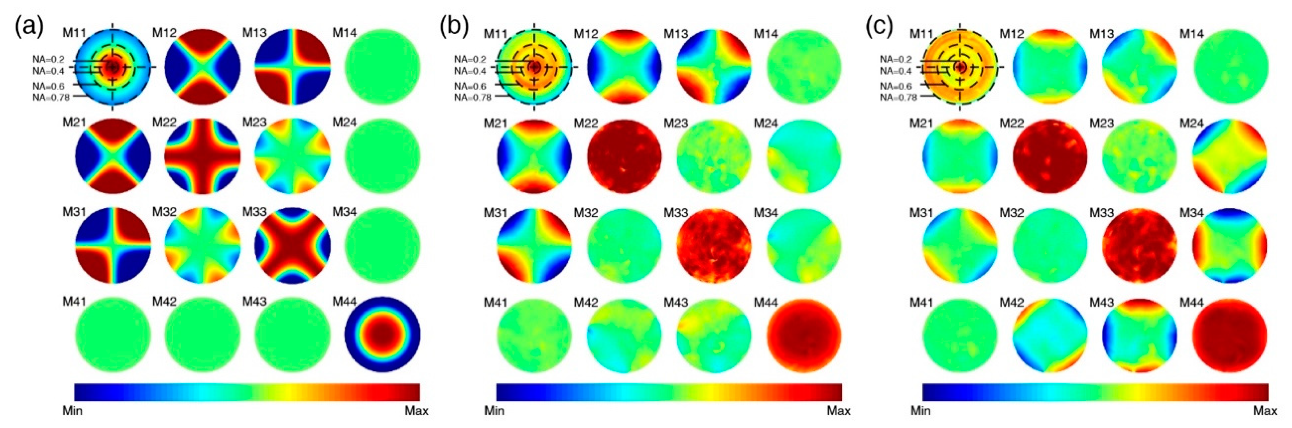
3.1. Theoretical Calculated Mueller Matrix of the Spherical Lens

As introduced above, we used vectorial ray-tracing methods to calculate the Mueller matrix of the spherical lens based on the 4-f lens system, as shown in Figure 4. In this system, the plane wave light was focused to the focal point by the first lens, then the spherical wave was collected by the second lens and converted into a plane wave. It should be noted that the electric vector maintained its direction concerning a meridional plane, and we assumed that there was no stray ray presented in this optical system.
Here, the generalized 3 × 3 Jones matrix and ordinary 2 × 2 Jones matrix of the lens are represented by GJn and Jn, where n = 1, 2 denote the first and second lens, respectively. GJn is derived by Equations (13) and (14) as:
G J 1 = R ( ϕ ) I L ( θ ) R ( ϕ ) ,
G J 2 = R ( ϕ ) L ( θ ) I R ( ϕ ) ,
and Jn is the upper-left 2 × 2 submatrix of GJn. Considering that the deduction processes were identical for both J1 and J2, we represented the Jones matrix and Mueller matrix of the lens by using J and M, respectively, in the following equations as:
J = 1 2 [ T + + T cos 2 ϕ T sin 2 ϕ T sin 2 ϕ T + T cos 2 ϕ ] ,
T + = τ p cos θ + τ s , T = τ p cos θ τ s ,
then M can be derived as Equations (17) and (18):
M = A ( J J * ) A 1 ,
A = [ 1 0 0 1 1 0 0 1 0 1 1 0 0 i i 0 ] ,
where * denotes the Kronecker product. Then, M can be written as Equations (19)–(21):
M t ( θ , ϕ ) = T 4 diag ( 1 , 1 , 1 , 1 ) + 1 4 [ T + 2 Acos 2 ϕ 2 Asin 2 ϕ 0 2 Acos 2 ϕ T + cos 4 ϕ T + sin 4 ϕ 2 Bsin 2 ϕ 2 Asin 2 ϕ T + sin 4 ϕ T + cos 4 ϕ 2 Bcos 2 ϕ 0 2 Bsin 2 ϕ 2 Bcos 2 ϕ T + ] ,
T + = | t + | 2 , T = | t | 2 , A = Re { t + t * } , B = Im { t + t * } ,
t + = t + t , t = t t ,
We integrated Equation (19) to obtain the value changes of the Mueller matrix elements, as Equation (22) shows:
M t ¯ = 1 π NA 2 D O M t ( θ , ϕ ) dS      = 1 4 NA 2 0 α diag ( T + + T , T , T , T + T ) × sin 2 θ d θ .
where Do is the exit pupil, α is the semi-convergence angle of the lens, and the denominator πNA2 is included to mitigate the effect of NA on the signal strength

3.2. Mueller Matrix Spectrum at the Back Focal Plane of the High-NA Lens

3.2.1. Calculated Mueller Matrix Spectrum of the Uncoated Spherical Lens Model

Figure 5 shows the Mueller matrices of the spectrum of plane waves from the exit pupil for the uncoated spherical lens model (a) (theoretical results), uncoated aspherical lens (b) (measured results), and coated aspherical lens (c) (measured results). In Figure 5, the M11 elements show the normalized light-intensity maps. The other 15 elements are normalized according to the M11. In the M11 elements, we used the black dotted circles to mark the locations of the convergence angle corresponding to different NA values.
First, we can see in Figure 5a of the calculated Mueller matrix for the uncoated spherical lens model that, as the NA increased from 0.2 to 0.78 (from the center to the outside), the light-intensity value in the M11 element decreased accordingly, indicating that the light reflected at the large convergence angle enhanced, and the transmitted light reduced. In addition, the values of the diagonal elements decreased, indicating that the increasing NA values led to depolarization. In the upper-left 3 × 3 submatrix, the larger NA resulted in an increase in the absolute values of the off-diagonal elements M12, M13, M21, and M31, which represented prominent diattenuation and optical rotation properties. Moreover, the values of M22 and M33 elements, and the upper-left 3 × 3 nondiagonal elements, showed characteristic periodic intensity variations with the changes in azimuth orientation. It can also be seen that the elements of the fourth row and column are empty, indicating that the ideal uncoated lens had no linear birefringence.
Here, the results derived based on the Huygens–Fresnel principle demonstrated that the reflected light of the lens contributed to the polarization aberrations. The element variations were induced by the reflectance difference where transmittance of the p-component parallel to the meridional plane was always larger than that of the s-component perpendicular to the meridional plane. The transmittance difference resulted in the inhomogeneous polarization distribution in the exit pupil, as well as the Mueller matrix elements. Thus, attenuating reflected light is of great importance for reducing various polarization aberrations including diattenuation, depolarization, and optical rotation.

3.2.2. Measured Mueller Matrix Spectrum of the Uncoated and Coated Aspherical Lenses

Secondly, we analyzed the polarization aberrations introduced by aspherical lenses with different NA values. As can be seen in Figure 5b,c, the increase in the NA value led to a decrease in the M11 elements, or in other words, the portion of transmitted light. Meanwhile, the values of the diagonal M22, M33, and M44 elements decreased with an increase in the NA. For the M12, M13, M21, and M31 elements, the obvious nonzero value appearing in the high-NA areas meant that diattenuation existed. It can also be seen that, for the M24, M34, M42 and M43 elements of the uncoated aspherical lens, they exhibited some random and irregular nonzero value distributions, while those elements of the coated aspherical lens additionally showed periodical intensity changes in the high-NA areas, indicating linear retardance was generated for such aspherical lens.
In summary, by comparing Figure 5a–c, it can be seen that the intensities of the M11 element of aspherical lenses were higher than that of the spherical lens. In addition, the M11 element intensity of the coated lenses was higher than that of the uncoated lenses, which meant the ratio of reflected light was lower. Compared to the spherical lens, both the uncoated and coated aspherical lenses showed higher values for the diagonal elements and smaller values for the upper-left 3 × 3 nondiagonal elements, which suggested that attenuating the reflected light suppressed the difference between the p- and s-components of the transmittance light and helped to reduce depolarization, linear diattenuation, and optical rotation. In addition, for the M24, M34, M42, and M43 elements, both the aspherical lenses showed some random nonzero values, rather than theoretically zero values, which may have been due to the annealing of the lens producing the stress birefringence. The stress birefringence also contributed to the uneven values of the M23 and M32 elements. We noticed that in Figure 5c, the M24, M34, M42, and M43 elements showed obvious periodical intensity distributions in the outside area of high NA. This may have been introduced by the linear birefringence of the MgF2 antireflection film. The transmission beams passed through longer optical paths in the margin areas/high-NA areas of the antireflection film, contributing to the higher linear retardance values. In general, using the aspherical lens, coating the lens with low-birefringent antireflection film, and improving the annealing are applicable methods to reduce polarization aberrations.

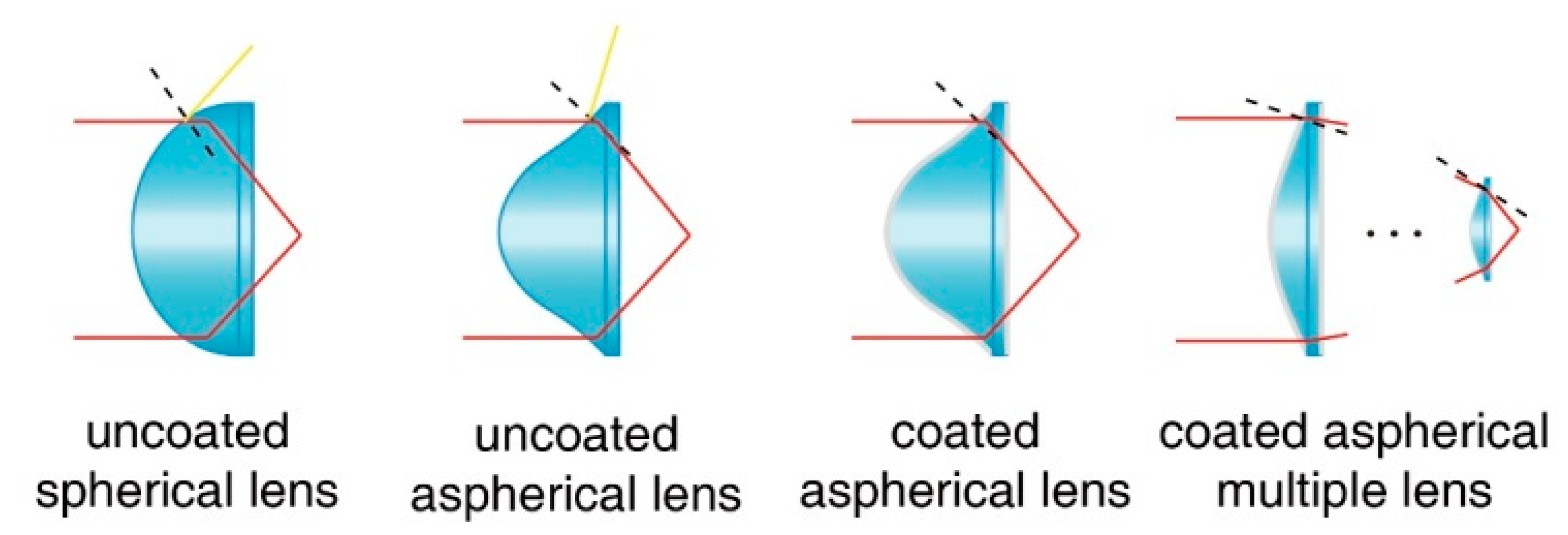
3.3. Multiple-Lens Design for Elimination of Polarization Aberrations

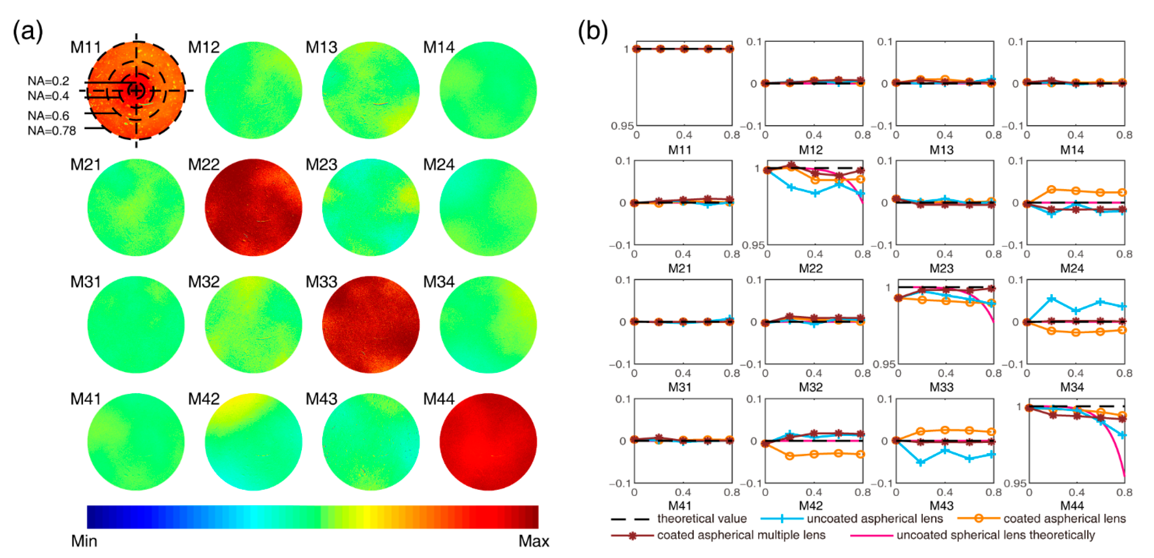
3.3.1. Measured Mueller Matrix Spectrum of Aspherical Multiple Lenses Coated with CaF2

Based on the analysis of Mueller matrix above, to eliminate the polarization aberrations of the high-NA lens, we designed the aspherical CaF2-coated multiple-lens scheme. In this study, two uneven-sized aspherical lenses with CaF2 antireflection film coatings, which had limited birefringence, were arranged in a line to assure that the light incident angles were less than 36 degrees on each plane of incidence. The measured Mueller matrix of the spectrum of plane waves from the exit pupil of the system is shown in Figure 6a. It can be seen that the Mueller matrix of each location of the exit pupil was close to a unit matrix. Compared with the lens schemes in Figure 5a–c, the M11 element showed a higher light transmittance. The value of the non-M11 diagonal element was close to 1, which showed that the depolarization was low. The value of the off-diagonal element was close to 0, and there was no obvious periodic distribution of polarization aberrations in the high-NA area, indicating that the diattenuation, optical rotation, and retardance were all suppressed. Although there were still some residual reflections and stress-induced birefringence in the M11 and M42 elements, the total polarization aberrations were removed satisfactorily by using the aspherical CaF2-coated multiple-lens system. Specifically, for the 48.6 half-convergence angle (NA = 0.75) location of the exit pupil, the mean value of the error of each non-M11 element was less than 1%.

3.3.2. Mueller Matrix of the High-NA Lens in the Image Plane

For applications such as polarization microscopy and sensing, the polarization aberrations of the high-NA lens may have a prominent influence on the results. Figure 6b shows the average results of Mueller matrix elements for the four high-NA lens systems: uncoated spherical lens (pink lines), uncoated aspherical lens (blue lines), coated aspherical lens (orange lines), and coated aspherical multiple lenses (purple lines), with NA increases from 0 to 0.2, 0.4, 0.6, and 0.78.
It can be observed in Figure 6b that, with an increase in NA, the values of the M22, M33, and M44 curves of the uncoated and coated aspherical high-NA systems decreased. Meanwhile, it can be seen that the values of the diagonal elements of the coated aspherical multiple-lens high-NA system were relatively stable when the NA increased. Compared to those of other high-NA lens systems, the M22, M33, and M44 element values for the proposed coated aspherical multiple-lens system were much closer to the ideal theoretical values when the NA was increased to 0.78. For the nondiagonal elements, the values for M12, M13, M14, M21, M31, M41, M23, and M32 were all close to the theoretical zero value. The nonzero values for the M24, M34, M42, and M43 element curves of three aspherical-lens high-NA systems showed the existence of linear birefringence. However, the curves of the M24, M34, M42, and M43 elements of the multiple aspherical-lens high-NA system with the CaF2 coating film had the smallest values and fluctuations among the three systems.
As shown in Equation (22), in practical applications that do not involve techniques such as focal plane filtering, the vector rays of the back focal plane are integrated to compensate each other. This means that for the measurement and imaging systems, part of the polarization aberrations may not be obvious. However, it is worth mentioning that the depolarization still exists, and the depolarization induced by the lens can be introduced into the measurement results of the sample. Suppressing reflected light can effectively reduce this type of depolarization. The retardance induced by the lens also must be suppressed, including that from its coating material. In general, the designed coated aspherical multiple lenses showed smaller polarization aberrations compared with the other lenses when the NA was increased.

3.3.3. MMPD Results for the High-NA Lens in the Image Plane

For a more quantitative comparison of the main polarization properties, we calculated the parameters for the Mueller matrix polar decomposition (MMPD), which comprised the depolarization (Δ), diattenuation (D), and linear retardance (δ) of the medium, as shown in Equations (9)–(11). Figure 7 shows the MMPD parameters of three different standard samples for the four high-NA systems: depolarization of air with an ideal value of 0, as shown in Figure 7a; diattenuation of a linear polarizer with an ideal value of 1, as shown in Figure 7b; and linear retardance of a quarter-wave retarder with an ideal value of π/2, as shown in Figure 7c. The standard deviation of each measurement result is marked in the graph to show the data distribution. During the measurements, the standard samples were placed in the focal plane (E1) of different high-NA systems to obtain the MMPD parameters.
First, as we can observe in Figure 7a, with an increase in the NA, the depolarization values of the three single-lens high-NA systems, which should have had no depolarization properties, rose prominently. In particular, the depolarization curve of the spherical lens model (pink line) rose more dramatically compared to those of the other two aspherical single-lens systems (blue and orange lines). It can also be seen that the uncoated aspherical system produced a larger depolarization than that of the coated ones. Second, Figure 7b shows that with an increase in the NA, the diattenuation values of all the high-NA systems of the linear polarizer, the ideal linear diattenuation of which should be 1, decreased due to the polarization aberrations of the high-NA systems. However, it can be seen that the values of Δ and D of the coated aspherical multiple-lens high-NA system were much closer to the theoretical values compared to the other single-lens systems. Last, in Figure 7c, it can be seen that the linear-retardance curve of the spherical-lens system model (pink line) showed no deviation from the ideal value, which should be π/2 for the quarter-wave retarder. However, the linear-retardance curves of the aspherical systems fluctuated randomly. The results shown in Figure 7 demonstrated that the introduction of aspherical lenses and the coating film to the high-NA system can be beneficial to reducing the polarization aberrations of depolarization and diattenuation, while to reduce the polarization aberrations of linear retardance induced by the aspherical lenses and coating films, lenses and films of fluorite can be considered. For instance, the proposed CaF2-film-coated aspherical multiple-lens scheme could reduce the polarization aberrations prominently in the high-NA imaging system.

4. Discussion

In this paper, the polarization aberrations of high-NA lenses were analyzed via a Mueller matrix approach both theoretically and experimentally. The Mueller matrices of both the back focal plane and the image plane of four high-NA lens systems were presented. It was found that through suppressing the ratio of reflected light and improving the lens-production technology, the polarization aberrations of high-NA lenses can be reduced.
Compared with the previous studies, our work made two advances:
(1) First, we verified the origin of the polarization aberrations of spherical lenses, and extensively studied such effects with aspherical lenses and a coating film.
(2) Second, we proposed a scheme of adopting multiple coated aspherical lenses to eliminate the polarization aberrations in applications based on high-NA lenses.
For more detailed discussions, as well as further applications:
(1) First, this work verified both theoretically and experimentally that the difference between the s- and p-polarization components of transmitted light can induce diattenuation, depolarization, and optical rotation. It also validated the existence of stress-induced birefringence.
(2) Second, we studied the polarization effect of aspherical lenses and antireflection film. Previously, due to limitations of manufacturing technology, such analysis was not fully conducted, and was confined to the traditional spherical lens. Recently, aspherical lenses and coating technology have been further developed, and are becoming essential components in modern optics, including in remote sensing, photogrammetry, microscopy, and other applications. It was shown that the aspherical lens not only had advantages in correcting aberrations, but also could modify the incidence angle to suppress the reflected light. Similarly, the antireflection film also helped to minimize the diattenuation and depolarization by reducing the difference between the s- and p-components. We also found in our experiments that in addition to the annealing process, the coating material could also lead to stress-induced birefringence. Hence, in the applications that involve vectorial information, low-birefringent material should be chosen for the lens coating.
(3) Finally, we proposed a scheme that used multiple coated aspherical lenses to reduce polarization aberrations, which not only confirmed the conclusions above, but also provided new insights for the aberration optimization of lenses in the future.
The proposed scheme can be useful for optical imaging and sensing applications based on vectorial information. For instance:
(1) In the application of vectorial information extraction and interference of light on the back focal plane, the effects of different polarization aberrations—including diattenuation, depolarization, optical rotation, and retardance—should be taken into consideration, in order to retrieve the correctness of the acquired vectorial information;
(2) In imaging and measurement applications such as photogrammetry and microscopy, the effects of the depolarization and retardance should be removed while analyzing the target information.
For validation, a comparative experiment is demonstrated in Figure 8, in which a common objective lens (NA 0.6) and a cascading coated aspherical multiple-lens combination (NA 0.6) were respectively mounted in a transmission Mueller matrix polarimeter. We chose a vortex retarder (m = 1, π, 100/λ, Lbtek Co., Ltd., Shenzhen, GD, China) as the testing sample; its theoretical linear retardance and fast axis orientation distribution are shown in Figure 8a.
Figure 8b,c show the vectorial information—linear retardance values (left) and fast axis orientations (right)—of the vortex retarder obtained from MMPD parameters δ and θ measured using the common objective lens (b) and cascading coated aspherical multiple-lens combination (c), respectively. The comparison between (b) and (c) demonstrates that the common objective lens introduced obvious errors to the measurement results. When using the lens combination to suppress polarization aberrations, it can be seen in Figure 8c that the fast axis orientation map was consistent with the theoretical distribution shown in Figure 8a, and the measured linear-retardance values were close to π. The multiple coated aspherical lenses with suppressed aberrations revealed the vectorial information of the sample more precisely.
The comparative observation proved the importance of this work: that the polarization aberrations of the lens should be corrected properly, otherwise it can strongly affect the correctness of the vectorial information detection of targets in a wide range of fields. A major application of the work in microscopy is producing high-NA condenser and objective lenses with suppressed polarization aberrations to improve both the imaging resolution and vectorial-information precision. Another potential application is in polarization remote sensing of forests and oceans [12,43,44], in which high-precision polarization cameras are essential. For instance, an emerging remote-sensing method, polarized hyperspectral imaging, which combines the benefits of polarized and hyperspectral information [45], can provide various extra polarization parameters to help discriminate and classify the objects presented in the images quantitatively. A wide-angle (high-NA) camera lens with a large field of view and suppressed polarization aberrations can improve the precision of vectorial information acquisition, which is important in the application of polarized remote-sensing cameras. In summary, the results obtained in this study can not only help to improve the performance of polarization measuring and imaging with high-NA lenses, but also provide a criterion for advanced lens design and production for other applications, such as vectorial-information sensing.

5. Conclusions

High-NA lenses are commonly used components in various optical systems, including aerial cameras, microscopes, and endoscopes, in which a high-quality beam and the correctness of the vectorial information are needed. The intrinsic polarization aberrations of lenses, which introduce disorder to the input SOPs, have gained public attention. In this work, we studied the origin of such polarization aberrations, and analyzed the intrinsic polarization aberrations induced by high-NA lenses both theoretically and experimentally. We analyzed the aberration effects of different high-NA lenses by testing standard samples, including air, a linear polarizer, and a quarter-wave retarder. Their MMPD parameters of depolarization, diattenuation, and linear retardance were studied in detail. Based on the analysis and comparison, we proposed strategies and analytic expressions for future compensating processes for hardware-based reduction solutions. A reduction in polarization aberrations would be beneficial to different types of optical imaging/sensing techniques with enhanced vectorial information. The preliminary imaging results obtained using a Mueller matrix polarimeter equipped with multiple coated aspherical lenses for a reduction in polarization aberrations confirmed that, together with the development of artificial intelligence and machine-vision technologies, the strategies proposed in this study have the potential to provide more precise information on the targets for applications spanning across classical optics, remote sensing, biomedical imaging, photogrammetry, and vectorial-information measurements.

Author Contributions

Conceptualization, Y.S. and B.C.; Data curation, Y.S. and B.C.; Formal analysis, Y.S.; Investigation, Y.S., B.C., and J.G.; Funding acquisition, H.H. and J.W.; Methodology, Y.S. and B.C.; Project administration, C.H. and H.H.; Software, Y.S.; Supervision, C.H., H.H., D.S.E., and H.M.; Writing—original draft, Y.S. and B.C.; Writing—review and editing, C.H., H.H., and D.S.E. All authors have read and agreed to the published version of the manuscript.

Funding

This research was funded by the National Natural Science Foundation of China (NSFC) (No. 61527826), and the Shenzhen Key Fundamental Research Project (No. JCYJ20210324120012035). Chao He would like to thank the support of the Junior Research Fellowship from St John’s College at University of Oxford.

Data Availability Statement

The data presented in this study are available upon request from the corresponding author.

Conflicts of Interest

The authors declare no conflict of interest.

References

  1. Chipman, R.; Chipman, L. Polarization Aberration Diagrams. Opt. Eng. 1989, 28, 282100. [Google Scholar] [CrossRef]
  2. Michael, R.; Shribak, I.; Inoue, S. Polarization aberrations caused by differential transmission and phase shift in high numerical aperture lenses: Theory, measurement, and rectification. Opt. Eng. 2002, 41, 943–945. [Google Scholar]
  3. Deuzé, J.; Bréon, F.; Devaux, C.; Goloub, P.; Herman, M.; Lafrance, B.; Maignan, F.; Marchand, A.; Nadal, F.; Perry, G. Remote sensing of aerosols over land surfaces from POLDER-ADEOS-1 polarized measurements. J. Geophys. Res. 2001, 106, 4913–4926. [Google Scholar] [CrossRef] [Green Version]
  4. Puttonen, E.; Suomalainen, J.; Hakala, T.; Peltoniemi, J. Measurement of reflectance properties of asphalt surfaces and their usability as reference targets for aerial photos. IEEE Trans. Geosci. Remote Sens. 2009, 47, 2330–2339. [Google Scholar] [CrossRef]
  5. Lin, S.-S.; Yemelyanov, K.M.; Pugh Jr, E.N.; Engheta, N. Polarization-based and specular-reflection-based noncontact latent fingerprint imaging and lifting. J. Opt. Soc. Am. 2006, 23, 2137–2153. [Google Scholar] [CrossRef]
  6. Zhanghao, K.; Chen, X.; Liu, W.; Li, M.; Liu, Y.; Wang, Y.; Luo, S.; Wang, X.; Shan, C.; Xie, H. Super-resolution imaging of fluorescent dipoles via polarized structured illumination microscopy. Nat. Commun. 2019, 10, 4694. [Google Scholar] [CrossRef] [Green Version]
  7. Hao, X.; Kuang, C.; Wang, T.; Liu, X. Effects of polarization on the de-excitation dark focal spot in STED microscopy. J. Opt. 2010, 12, 115707. [Google Scholar] [CrossRef]
  8. Wicker, K.; Heintzmann, R. Single-shot optical sectioning using polarization-coded structured illumination. J. Opt. 2010, 12, 084010. [Google Scholar] [CrossRef]
  9. Lu, S.-Y.; Chipman, R.A. Interpretation of Mueller matrices based on polar decomposition. J. Opt. Soc. Am. 1996, 13, 1106–1113. [Google Scholar] [CrossRef]
  10. Ortega-Quijano, N.; Arce-Diego, J.L. Mueller matrix differential decomposition for direction reversal: Application to samples measured in reflection and backscattering. Opt. Express 2011, 19, 14348–14353. [Google Scholar] [CrossRef] [Green Version]
  11. He, H.; Zeng, N.; Du, E.; Guo, Y.; Li, D.; Liao, R.; Ma, H. A possible quantitative Mueller matrix transformation technique for anisotropic scattering media. Photonics Lasers Med. 2013, 2, 129–137. [Google Scholar] [CrossRef]
  12. Nunziata, F.; Gambardella, A.; Migliaccio, M. On the degree of polarization for SAR sea oil slick observation. ISPRS J. Photogramm. Remote Sens. 2013, 78, 41–49. [Google Scholar] [CrossRef]
  13. Lawless, R.; Xie, Y.; Yang, P.; Kattawar, G.W.; Laszlo, I. Polarization and effective Mueller matrix for multiple scattering of light by nonspherical ice crystals. Opt. Express 2006, 14, 6381–6393. [Google Scholar] [CrossRef] [PubMed]
  14. Redemann, J.; Turco, R.; Liou, K.; Russell, P.; Bergstrom, R.; Schmid, B.; Livingston, J.; Hobbs, P.; Hartley, W.; Ismail, S. Retrieving the vertical structure of the effective aerosol complex index of refraction from a combination of aerosol in situ and remote sensing measurements during TARFOX. J. Geophys. Res. 2000, 105, 9949–9970. [Google Scholar] [CrossRef] [Green Version]
  15. Li, D.; Chen, F.; Zeng, N.; Qiu, Z.; He, H.; He, Y.; Ma, H. Study on polarization scattering applied in aerosol recognition in the air. Opt. Express 2019, 27, A581–A595. [Google Scholar] [CrossRef]
  16. Tuchin, V.V. Polarized light interaction with tissues. J. Biomed. Opt. 2016, 21, 071114. [Google Scholar] [CrossRef] [Green Version]
  17. He, C.; He, H.; Chang, J.; Chen, B.; Ma, H.; Booth, M.J. Polarisation optics for biomedical and clinical applications: A review. Light Sci. Appl. 2021, 10, 194. [Google Scholar] [CrossRef]
  18. He, H.; Liao, R.; Zeng, N.; Li, P.; Chen, Z.; Liu, X.; Ma, H. Mueller matrix polarimetry—An emerging new tool for characterizing the microstructural feature of complex biological specimen. J. Light. Technol. 2019, 37, 2534–2548. [Google Scholar] [CrossRef]
  19. Ramsey, D.A.; Ludema, K.C. The influences of roughness on film thickness measurements by Mueller matrix ellipsometry. Rev. Sci. Instrum. 1994, 65, 2874–2881. [Google Scholar] [CrossRef] [Green Version]
  20. Zhang, S.; Jiang, H.; Gu, H.; Chen, X.; Liu, S. Remote attitude sensing based on high-speed Mueller matrix ellipsometry. Int. Arch. Photogramm. Remote Sens. Spatial Inf. Sci. 2020, 43, 607–614. [Google Scholar] [CrossRef]
  21. Arteaga, O.; Baldrís, M.; Antó, J.; Canillas, A.; Pascual, E.; Bertran, E. Mueller matrix microscope with a dual continuous rotating compensator setup and digital demodulation. Appl. Opt. 2014, 53, 2236–2245. [Google Scholar] [CrossRef] [PubMed] [Green Version]
  22. Wang, Y.; He, H.; Chang, J.; He, C.; Liu, S.; Li, M.; Zeng, N.; Wu, J.; Ma, H. Mueller matrix microscope: A quantitative tool to facilitate detections and fibrosis scorings of liver cirrhosis and cancer tissues. J. Biomed. Opt. 2016, 21, 071112. [Google Scholar] [CrossRef] [PubMed] [Green Version]
  23. Dong, Y.; Wan, J.; Si, L.; Meng, Y.; Dong, Y.; Liu, S.; He, H.; Ma, H. Deriving polarimetry feature parameters to characterize microstructural features in histological sections of breast tissues. IEEE. Trans. Biomed. Eng. 2020, 68, 881–892. [Google Scholar] [CrossRef]
  24. Inoue, S. A method for measuring small retardations of structures in living cells. Exp. Cell Res. 1951, 2, 513–517. [Google Scholar] [CrossRef]
  25. Inoué, S.; Hyde, W.L. Studies on depolarization of light at microscope lens surfaces: II. The simultaneous realization of high resolution and high sensitivity with the polarizing microscope. J. Biophys. Biochem. Cytol. 1957, 3, 831. [Google Scholar] [CrossRef] [PubMed]
  26. Wolf, E. Electromagnetic diffraction in optical systems-I. An integral representation of the image field. Proc. R. Soc. A Math. Phys. Eng. Sci. 1959, 253, 349–357. [Google Scholar]
  27. Török, P.; Varga, P.; Laczik, Z.; Booker, G. Electromagnetic diffraction of light focused through a planar interface between materials of mismatched refractive indices: An integral representation. J. Opt. Soc. Am. A 1995, 12, 325–332. [Google Scholar] [CrossRef]
  28. Török, P.; Higdon, P.; Wilson, T. On the general properties of polarised light conventional and confocal microscopes. Opt. Commun. 1998, 148, 300–315. [Google Scholar] [CrossRef]
  29. Munro, P.; Török, P. Properties of high-numerical-aperture Mueller-matrix polarimeters. Opt. Lett. 2008, 33, 2428–2430. [Google Scholar] [CrossRef]
  30. He, C.; Chang, J.; Hu, Q.; Wang, J.; Antonello, J.; He, H.; Liu, S.; Lin, J.; Dai, B.; Elson, D.S. Complex vectorial optics through gradient index lens cascades. Nat. Commun. 2019, 10, 4264. [Google Scholar] [CrossRef] [Green Version]
  31. Wang, C.; Chen, X.; Gu, H.; Jiang, H.; Zhang, C.; Liu, S. On the limits of low-numerical-aperture imaging scatterometry. Opt. Express 2020, 28, 8445–8462. [Google Scholar] [CrossRef] [PubMed]
  32. Shen, Y.; Huang, R.; He, H.; Liu, S.; Dong, Y.; Wu, J.; Ma, H. Comparative study of the influence of imaging resolution on linear retardance parameters derived from the Mueller matrix. Biomed. Opt. Express 2021, 12, 211–225. [Google Scholar] [CrossRef] [PubMed]
  33. Wolfe, J.; Chipman, R. Reducing symmetric polarization aberrations in a lens by annealing. Opt. Express 2004, 12, 3443–3451. [Google Scholar] [CrossRef] [PubMed]
  34. Azzam, R. Photopolarimetric measurement of the Mueller matrix by Fourier analysis of a single detected signal. Opt. Lett. 1978, 2, 148–150. [Google Scholar] [CrossRef]
  35. Chenault, D.B.; Pezzaniti, J.L.; Chipman, R.A. Mueller matrix algorithms. In Proceedings of the Polarization Analysis and Measurement, San Diego, CA, USA, 11 December 1992; pp. 231–246. [Google Scholar]
  36. Zhou, J.; He, H.; Chen, Z.; Wang, Y.; Ma, H. Modulus design multiwavelength polarization microscope for transmission Mueller matrix imaging. J. Biomed. Opt. 2018, 23, 016007. [Google Scholar] [CrossRef] [Green Version]
  37. Swami, M.; Manhas, S.; Buddhiwant, P.; Ghosh, N.; Uppal, A.; Gupta, P. Polar decomposition of 3 × 3 Mueller matrix: A tool for quantitative tissue polarimetry. Opt. Express 2006, 14, 9324–9337. [Google Scholar] [CrossRef]
  38. Wood, M.F.; Ghosh, N.; Moriyama, E.H.; Wilson, B.C.; Vitkin, I.A. Proof-of-principle demonstration of a Mueller matrix decomposition method for polarized light tissue characterization in vivo. J. Biomed. Opt. 2009, 14, 014029. [Google Scholar] [CrossRef]
  39. Dubreuil, M.; Babilotte, P.; Martin, L.; Sevrain, D.; Rivet, S.; Le Grand, Y.; Le Brun, G.; Turlin, B.; Le Jeune, B. Mueller matrix polarimetry for improved liver fibrosis diagnosis. Opt. Lett. 2012, 37, 1061–1063. [Google Scholar] [CrossRef] [Green Version]
  40. Pierangelo, A.; Nazac, A.; Benali, A.; Validire, P.; Cohen, H.; Novikova, T.; Ibrahim, B.H.; Manhas, S.; Fallet, C.; Antonelli, M.-R. Polarimetric imaging of uterine cervix: A case study. Opt. Express 2013, 21, 14120–14130. [Google Scholar] [CrossRef]
  41. Liu, T.; Lu, M.; Chen, B.; Zhong, Q.; Li, J.; He, H.; Mao, H.; Ma, H. Distinguishing structural features between Crohn’s disease and gastrointestinal luminal tuberculosis using Mueller matrix derived parameters. J. Biophotonics 2019, 12, e201900151. [Google Scholar] [CrossRef]
  42. Ghosh, N.; Wood, M.F.; Vitkin, I.A. Mueller matrix decomposition for extraction of individual polarization parameters from complex turbid media exhibiting multiple scattering, optical activity, and linear birefringence. J. Biomed. Opt. 2008, 13, 044036. [Google Scholar] [CrossRef] [PubMed]
  43. Du, P.; Samat, A.; Waske, B.; Liu, S.; Li, Z. Random forest and rotation forest for fully polarized SAR image classification using polarimetric and spatial features. ISPRS J. Photogramm. Remote Sens. 2015, 105, 38–53. [Google Scholar] [CrossRef]
  44. Yan, L.; Li, Y.; Chandrasekar, V.; Mortimer, H.; Peltoniemi, J.; Lin, Y. General review of optical polarization remote sensing. Int. J. Remote Sens. 2020, 41, 4853–4864. [Google Scholar] [CrossRef]
  45. Tonizzo, A.; Zhou, J.; Gilerson, A.; Twardowski, M.S.; Gray, D.J.; Arnone, R.A.; Gross, B.M.; Moshary, F.; Ahmed, S.A. Polarized light in coastal waters: Hyperspectral and multiangular analysis. Opt. Express 2009, 17, 5666–5683. [Google Scholar] [CrossRef] [PubMed] [Green Version]
Figure 1. Schematics of light-beam propagation through a lens. (a) Focusing and (b) collection of light in a high-NA lens system.
Remotesensing 14 01932 g001
Figure 2. Four designs used in high-NA lens systems. The red solid lines show the light paths, the yellow solid lines show the reflection light paths of the interface surface, the black dotted lines show the normal lines of the interface, and the coated lenses are represented by the gray boundary on the surface.
Remotesensing 14 01932 g002
Figure 3. Schematic of Mueller matrix polarimeter.
Remotesensing 14 01932 g003
Figure 4. Schematic of a simplified high-NA 4-f lens system.
Remotesensing 14 01932 g004
Figure 5. Mueller matrices of the spectrum of plane waves from the exit pupil for (a) uncoated spherical lens model (theoretical calculation), (b) uncoated aspherical lens system, and (c) coated aspherical lens system. The areas corresponding to different NA values are labeled with black dotted lines in the M11 element. The M11 elements were normalized to [0, 1], while all the other elements were normalized with the M11 to [–1, 1]. The color bars in (ac) are [0, 1] for the M11 element; [0.8, 1] for the M22, M33, and M44 elements; and [−0.25, 0.25] for other nondiagonal elements.
Remotesensing 14 01932 g005
Figure 6. (a) Measured Mueller matrix of the spectrum of plane waves from exit pupil for aspherical multiple lenses coated with CaF2. The areas of different NA values are labeled with black lines in the M11. The M11 element was normalized to [0, 1], while all other elements were normalized with the M11 to [−1, 1]. The color bar is [0.8, 1] for the M22, M33, and M44 elements; and [−0.25, 0.25] for other nondiagonal elements. (b) Average values of Mueller matrices for four high-NA lens systems: uncoated spherical lens (pink lines), uncoated aspherical lens (blue lines), coated aspherical lens (orange lines) and coated aspherical multiple lenses (purple lines), with NA increases from 0 to 0.2, 0.4, 0.6, and 0.78. The black dotted lines show the theoretical values. Here, air was used as the standard sample. All Mueller matrix elements were normalized with the M11. The measured average values with NA 0, 0.2, 0.4, 0.6, and 0.78 of the M44 element for the uncoated aspherical lens were 0.999 ± 7.09 × 10⁻⁵, 0.999 ± 7.70 × 10⁻⁵, 0.997 ± 7.61 × 10⁻⁴, 0.990 ± 8.41 × 10⁻⁵, and 0.981 ± 8.85 × 10⁻⁵, respectively; and of the M24 element for the coated aspherical lens were −0.00340 ± 1.45 × 10⁻⁴, 0.0312 ± 1.70 × 10⁻³, 0.0279 ± 8.93 × 10⁻⁴, 0.0238 ± 8.83 × 10⁻⁴, and 0.0242 ± 5.19 × 10⁻⁴, respectively.
Remotesensing 14 01932 g006
Figure 7. Experimental results of MMPD parameters (a) Δ of air, (b) D of a linear polarizer, and (c) δ of a quarter-wave retarder, for four high-NA lens systems: uncoated spherical lens (pink lines), uncoated aspherical lens (blue lines), coated aspherical lens (orange lines), and coated aspherical multiple lenses (purple lines), with NA increases from 0 to 0.2, 0.4, 0.6, and 0.78. The black dotted lines show the theoretical values.
Remotesensing 14 01932 g007
Figure 8. Comparative validation experiment between a common objective lens and a lens combination in suppressing polarization aberrations. (a) Schematic of the vortex retarder sample; (b) from left to right, the MMPD δ and θ results measured by the common objective lens; and (c) from left to right, the MMPD δ and θ results measured by the cascading coated aspherical multiple-lens combination.
Remotesensing 14 01932 g008
Publisher’s Note: MDPI stays neutral with regard to jurisdictional claims in published maps and institutional affiliations.

