Technical Note

Distortionless 1/2 Overlap Windowing in Frequency Domain Anti-Jamming of Satellite Navigation Receivers

1
College of Electronic Science and Technology, National University of Defense Technology, Changsha 410073, China
2
Beijing BDStar Navigation Co., Ltd., Beijing 100080, China
*
Author to whom correspondence should be addressed.
Remote Sens. 2022, 14(8), 1801; https://doi.org/10.3390/rs14081801
Submission received: 20 February 2022 / Revised: 4 April 2022 / Accepted: 6 April 2022 / Published: 8 April 2022
(This article belongs to the Topic GNSS Measurement Technique in Aerial Navigation)

Abstract

:
Frequency-domain anti-jamming technology is a common anti-jamming method for satellite navigation receivers. 1/2 overlapping windowing can effectively solve the spectrum leakage in the frequency domain conversion process, but the traditional window function will cause the loss of signal energy. This paper proposes a window function design method with no loss of signal energy, which can effectively solve the signal energy loss caused by the window function. The feasibility of the proposed method is theoretically deduced, and the effectiveness of the proposed method is verified by simulation and measured data. Compared with the traditional window function, the signal-to-noise ratio improvement of the method proposed in this paper is better than 0.5 dB. The frequency domain anti-jamming processing is optimized, the signal-to-noise ratio loss caused by the anti-jamming processing is reduced, and the anti-jamming performance is indirectly improved. This plays an important role in the performance optimization of satellite navigation system links.

Graphical Abstract

1. Introduction

The satellite navigation system represented by GPS has developed by leaps and bounds in the past 20 years [1,2]. At present, four global satellite navigation systems such as GPS, Beidou, Galileo, and GLONASS have been constructed, which have become important information infrastructures worldwide [3,4,5,6]. The Satellite navigation system has been widely used in transportation, electricity, finance, and monitoring of mountains and bridges [7,8,9]. In addition, every mobile phone has satellite navigation functions [10]. In terms of military applications, satellite navigation systems are used in ships, aircraft, tanks, precision-guided bombs, and missiles [11,12,13]. Satellite navigation systems have played an important role in improving the combat effectiveness of combat platforms. Satellite navigation systems have shown great application value in both civilian and military applications.
However, with the rapid development of global radio technology and the large-scale application of satellite navigation systems, satellite navigation systems are inevitably subject to some intentional or unintentional interference [14,15,16]. The existing global satellite navigation systems all use medium and high-orbit constellations, and the geostationary orbit satellites. The orbital altitudes of medium and high-orbit constellates operate at an altitude of around the 20,000 km, and the GEO satellites’ orbital altitudes exceed 30,000 km, which are limited by the energy of the satellites, making it difficult for satellites to continuously transmit high-power navigation signals [17,18,19]. When the signal reaches the ground, the signal power is already very weak; its absolute level is about −130 dBm, which is 30 dB lower than the noise, for a receiver bandwidth of 20 MHz. Satellite navigation signals are mainly concentrated in the L-band. Due to the natural advantages of the L-band, some communication and radar signals are also in the L-band [20,21,22]. Although there is no spectrum overlap between systems, the spurious and leakage of communication and radar signals will affect the satellite navigation system, having a serious impact [23,24]. Weak navigation signals are highly susceptible to various intentional or unintentional interference. Satellite navigation jamming and anti-jamming have become a new combat style and have played an important role in recent local wars.
There are many factors involved in the satellite navigation receiver link, which influences the elimination of interference, including antennas, radio frequency channels, etc. If the receiver has been conducted, the hardware modules can’t be changed, and only the software can be improved. Therefore, with the wide application of satellite navigation systems, anti-jamming technology has also been developed rapidly [25,26,27]. According to the number of antennas, anti-jamming technology can be divided into single-antenna anti-jamming technology and array antenna anti-jamming technology [28,29,30,31]. Among them, the single-antenna anti-jamming technology has been widely used due to its advantages of low cost, high precision, and convenient installation. Most civil receivers adopt single-antenna anti-jamming technology. Frequency domain anti-jamming is the main means of single-antenna anti-jamming technology, and its advantages are high precision, high robustness, and wide application [32,33]. The realization of frequency domain anti-jamming technology involves the design of algorithms and window functions. The algorithm flowchart of frequency domain anti-jamming converts digital signals to the frequency domain, using the frequency domain characteristics of narrowband interference to suppress the interference spectrum. The window function needs to be adopted to suppress the spectral leakage while the Fast Fourier Transform (FFT) is performed. Due to the truncation effect of the signal, spectrum leakage will be caused, and the smaller the number of FFT points, the more serious the spectrum leakage; the larger the number of FFT points, the greater the computational complexity of the algorithm [34]. The existing method is to take an appropriate number of FFT points and perform 1/2 overlapping window processing, which theoretically suppresses the leakage of the spectrum [35].
In frequency domain anti-jamming processing, the window function will affect the signal reception performance. While researching frequency domain anti-jamming, we found that using the traditional window function design method, 1/2 overlapping windowing will lead to signal loss. Notably, this problem has not been reported publicly. In order to solve the problem of signal loss caused by overlapping windowing, this paper analyzes the signal loss caused by overlapping windowing from the mechanism and designs a window function design method without loss in theory. Obviously, a window function with no distortion is the best way to solve the signal loss problem. Simulation experiments and measured data verify the effectiveness of the proposed method.
This paper is organized as follows. In Section 2, the mathematical model of frequency domain anti-jamming and 1/2 overlapping windowing is introduced. Section 3 analyzes the influence of traditional 1/2 overlapped windowing on signal loss from two aspects of theory and simulation. Section 4 proposes a lossless window function design method, which is verified by simulation and measured data. In Section 5, the navigation receiver with software is used to suppress interference. Finally, the conclusion of this paper is given.

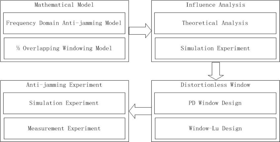
2. Mathematical Model

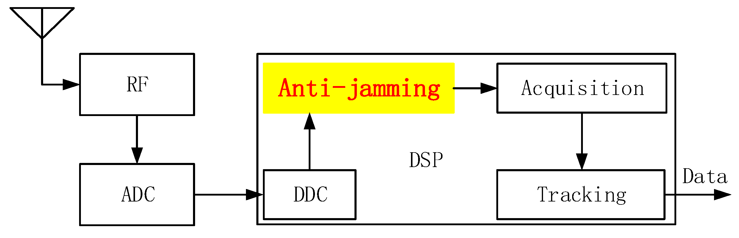
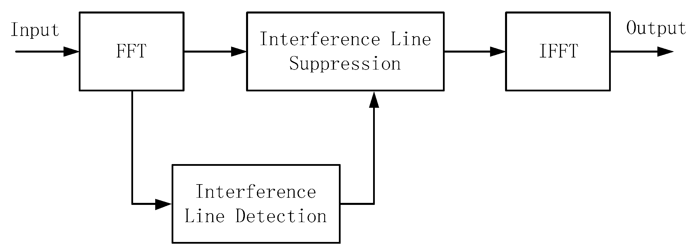
2.1. Frequency Domain Anti-Jamming Model

In a satellite navigation receiver, the antenna receives a navigation signal from the satellite and preprocesses the navigation signal through the radio frequency channel, including low-noise amplification, frequency mixing, filtering, intermediate frequency amplification and other links, which can be collectively referred to as analog signal processing; then, the analog signal is converted into a digital signal through an analog-to-digital converter (ADC) [36,37]. Digital signal processing (DDC) is usually carried out in FPGA (Field Programmable Gate Array) and DSP (Digital Signal Processing), signal flow is carried out in FPGA, and DSP is responsible for signal control and scheduling. The specific functional links include digital down-conversion, anti-jamming, capture, tracking and other processing; the carrier phase, code delay, and Doppler frequency information are output finally. Anti-jamming processing is part of digital signal processing. The frame of the satellite navigation receiver is shown in Figure 1.
Frequency domain anti-jamming is a common processing method for satellite navigation receivers. The received data is converted to the frequency domain through Fast Fourier Transform (FFT), and the interference spectrum is identified and suppressed by a filter, and then converted from the frequency domain to the time domain through Inverse Fast Fourier Transform (IFFT) [38]. The time-domain signal is performed for navigation signal processing. The basic principle diagram of frequency domain anti-jamming is shown in Figure 2 [39].

2.2. 1/2 Overlapping Windowing Model

According to the literature [40], in the FFT process, the truncation of the data length will cause spectrum leakage, and the spectrum leakage is related to the Fourier transform length, interference intensity and other factors [41]. Spectral leakage increases the difficulty of identifying interfering spectral lines. Therefore, literature [42] proposes a windowing method to reduce spectral leakage. Common window functions include Hanning window, Hamming window, Blackman window, Kaiser window, etc. [43]. The time domain graph of common window functions is shown in Figure 3.
Taking a single carrier with a signal-to-noise ratio of 30 dB as an example, the data length is 2048 points, and the Hanning window is selected for the typical window function to suppress the spectrum leakage. Figure 4 shows a comparison of the spectrum before and after using the Hanning window. By comparing the simulation results, the spectrum contrast before and after windowing is very obvious, and windowing significantly improves the problem of spectrum leakage and makes the identification of interference spectral lines easier.
However, windowing will cause loss of signal energy, and the amount of loss is related to signal characteristics; the greater the signal power, the greater the loss.
In satellite navigation receivers, the interference power is usually large, so windowing will cause a large loss of interference. Taking the BPSK (10) modulated Beidou signal as the analysis object, the simulated loss of the signal-to-noise ratio by windowing is shown in Figure 5. Combining Figure 4 and Figure 5, it can be seen that the Hanning window, Hamming window, and Blackman window have a greater impact on the input signal with high signal-to-noise ratio. This is because these three window functions are more focused in the time domain; that is, the spectral leakage is less impacted. The Kaiser window is more diffuse in the time domain, which is the signal-to-noise ratio of the input signal.
In the frequency domain anti-jamming processing of satellite navigation receivers, in order to reduce the loss caused by windowing, a 1/2 overlapping windowing method is proposed, which can effectively reduce the loss of windowing and is currently the mainstream frequency domain anti-jamming method. The interference processing architecture is shown in Figure 6. The weighting processing changing the delay is marked in red.

3. Influence of 1/2 Overlapping Windowing

According to the 1/2 overlapping windowing processing architecture shown in Figure 6, the 1/2 overlapping windowing processing is performed on the five window functions shown in Figure 3, and the time domain diagram thereof is shown in Figure 7, including different window functions and detailed data illustrations. In Figure 7, the first 1/2 and the last 1/2 window functions are the superposition processing of the starting and ending parts, which need not be considered for analysis. In the overlapping window processing part, except for the rectangular window, the other four window functions have different degrees of amplitude fluctuation. Among them, the fluctuation of the Blackman window is the largest, the fluctuation of the Kaiser window comes second, and the fluctuation of the Hanning window is the smallest.
Here, we take five typical window functions (rectangular window, Hanning window, Hamming window, Blackman window, and Kaiser window) as examples for simulation analysis. In the simulation experiment, the input is the PRN1 signal of Beidou B3I, the modulation method is BPSK-R(10), and the signal sampling rate is 25 MHz. The performance influence analysis of SNR is shown in Figure 8a. In order to more clearly see the loss of signal-to-noise ratio caused by 1/2 overlapping windowing, the rectangular window is used as the base, and the signal-to-noise ratio affected by other window functions is worsened; the result is shown in Figure 8b,c.
It can be seen from Figure 8 that the Blackman window has the greatest impact, followed by the Kaiser window; the Hanning window and Hamming window have less impact, which is consistent with the above theoretical analysis results. Secondly, the fluctuation of the Hanning window and Hamming window is the smallest. The fluctuation in the time domain after overlapping windowing is the root cause of the loss of SNR. Moreover, with the increase of the input SNR, the loss of 1/2 overlapping windowing shows an upward trend. This is because the SNR is affected by the fluctuation of overlapping windowing in the time domain. The more SNR, the bigger the influence.

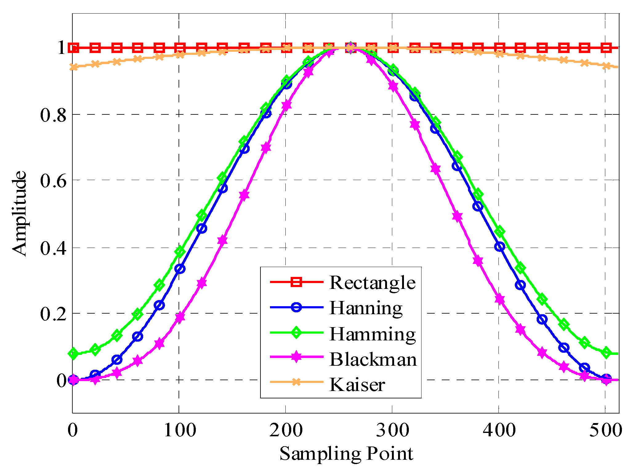
4. Distortionless Window Function

4.1. Design of a Distortionless Delay Window Function

From the above analysis of the influence of 1/2 overlapping windowing on the SNR of the input signal, it can be seen that the fundamental reason for the loss of signal SNR caused by 1/2 overlapping windowing is the fluctuation in the time domain after overlapping windowing. By designing the window function to reduce or even eliminate fluctuations, we can reduce or even eliminate the effect of 1/2 overlapping windowing.
As can be seen from Figure 6, in the process of 1/2 overlapping windowing, there are two places that need to be windowed, and the functions of the traditional method tasks in these two places are the same. Just because the two window functions are the same, the 1/2 overlapping windowing part has fluctuations in the time domain. The two window functions are defined as the punctual window function and the delay window function, respectively. In order to ensure that the overlapped windowing part does not fluctuate, the delay window function is now modified. The delay window function is calculated according to the punctual window function, expressed as follows:
w d e l a y = [ w t e m p ( N 2 + 1 : N ) w t e m p ( 1 : N 2 ) ]
where N is the length of window function and w t e m p is:
w t e m p = 1 w p u n c t u a l
Taking the Hanning window, Hamming window, Blackman window, and Kaiser window as examples, according to the delay window functions of Equations (1) and (2), the punctuality and delay window functions of four typical window functions are simulated and compared. The simulation results are shown in Figure 9.
In order to analyze the difference between the punctual and delay window functions more accurately, the difference between the punctual and delay window functions is aligned, and the results of difference value and detailed data are shown in Figure 10a,b, respectively.
It can be seen from Figure 9 and Figure 10 that there are differences in the punctual and delay of the above four typical window functions. Kaiser window is the largest, Blackman window comes second, and Hanning window is the smallest.
Using the punctual and delay window functions of the above four typical window functions to perform 1/2 overlapping windowing processing, the windowing effect is shown in Figure 11. Using different punctual and delay window functions, the overlapping windowing area is achieved without fluctuation.

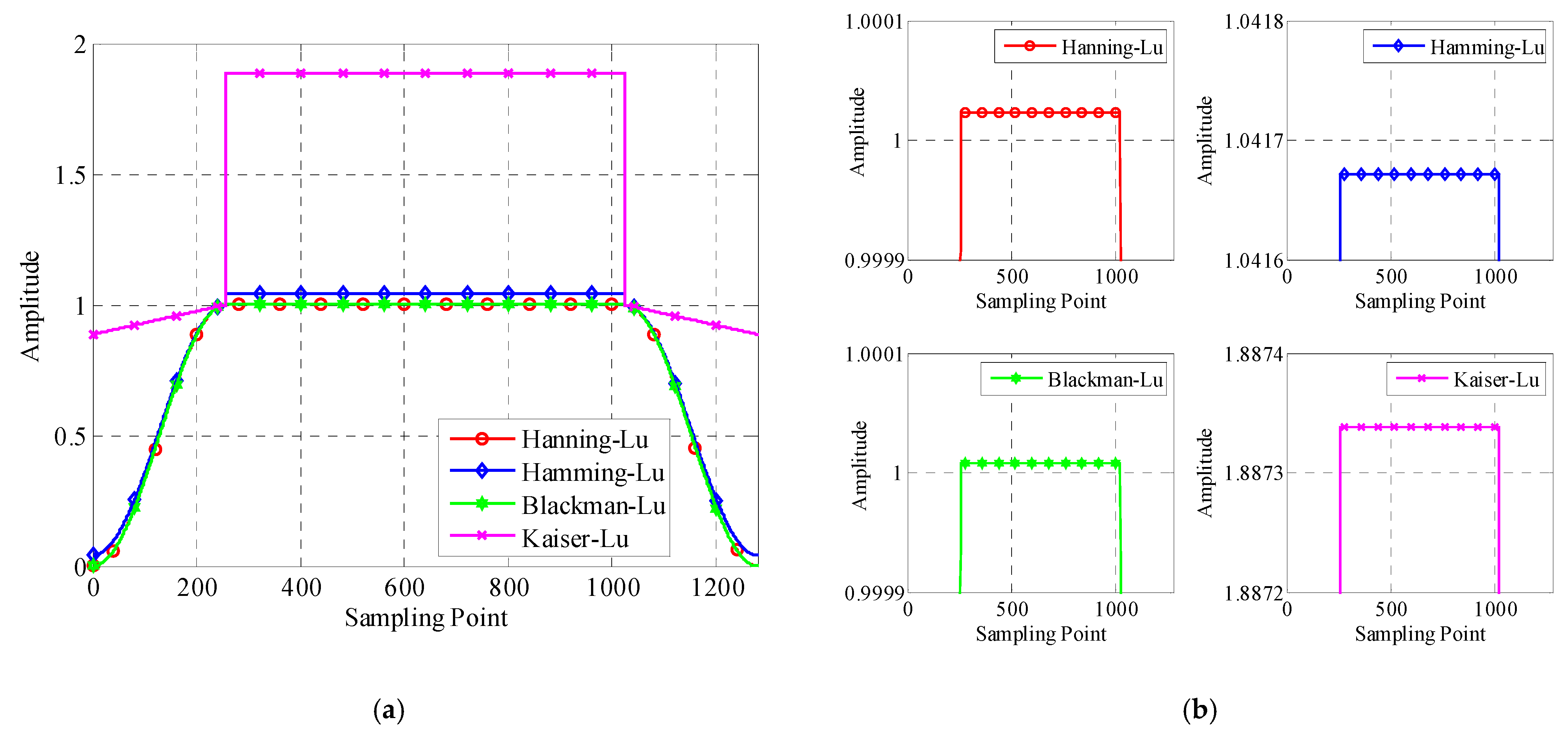
4.2. Design of a Distortionless Window Function

Taking the Hanning window as an example, in order to facilitate design and implementation, the punctual and delay window functions of the Hanning window are designed in a unified manner. This is named the Hanning-Lu window function, which is expressed as follows:
w H a n n i n g L u = ( w H a n n i n g p u n c t u a l + w H a n n i n g d e l a y ) / 2
where w H a n n i n g p u n c t u a l is the punctual window function of the Hanning window in Section 4.1 and w H a n n i n g d e l a y is the delay window function.
The distortionless design method of the Hamming window, Blackman window, and Kaiser window is the same as that of the Hanning window.
For the convenience of description, the traditional window functions are collectively called window, and the window functions proposed in this section are collectively called window-Lu.
The time-domain diagrams of four typical window-Lu window functions are shown in Figure 12.
In order to describe the difference between window-Lu and the traditional window function in a more detailed way, the difference between window-Lu and window is made; the result is shown in Figure 13a, and detailed data for a sampling rate of around 250 is shown in Figure 13b.
It can be seen from Figure 13 that the difference of the Blackman window function is the largest, followed by Kaiser, and the difference of the Hanning window function is the smallest.
Figure 14 shows the windowing effect of 1/2 overlapping windowing using four window-Lu window functions, including the overall experimental results and the detailed data of different window functions.
The punctual window function and the delay window function in Section 4.1 are unified to form the window-Lu window function, which can effectively solve the problem of fluctuation of the overlapping windowing area.

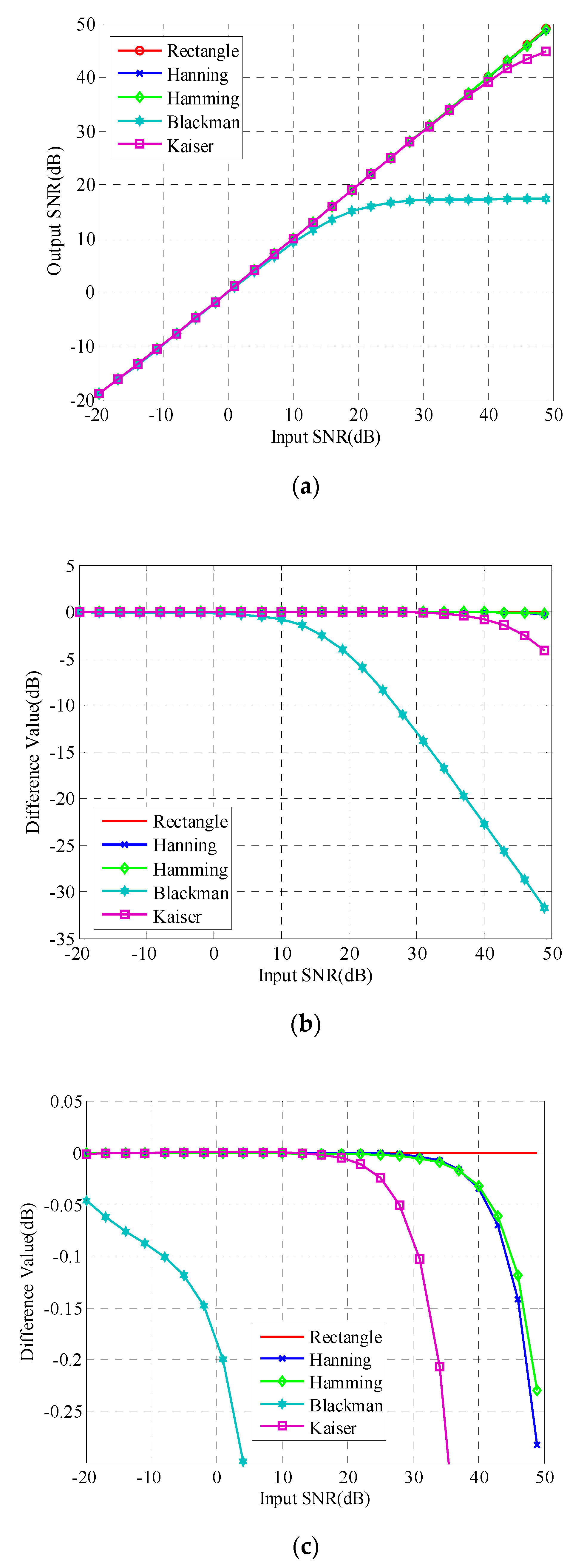
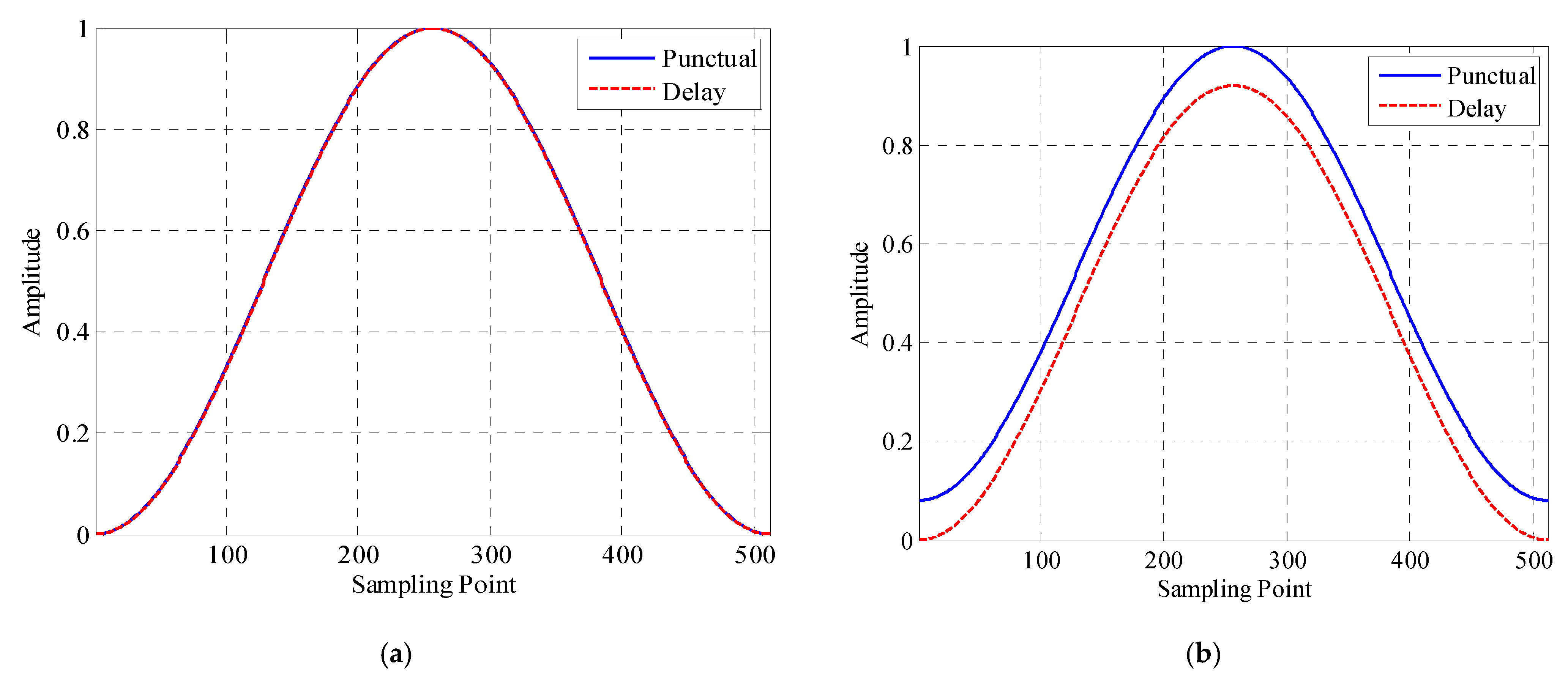
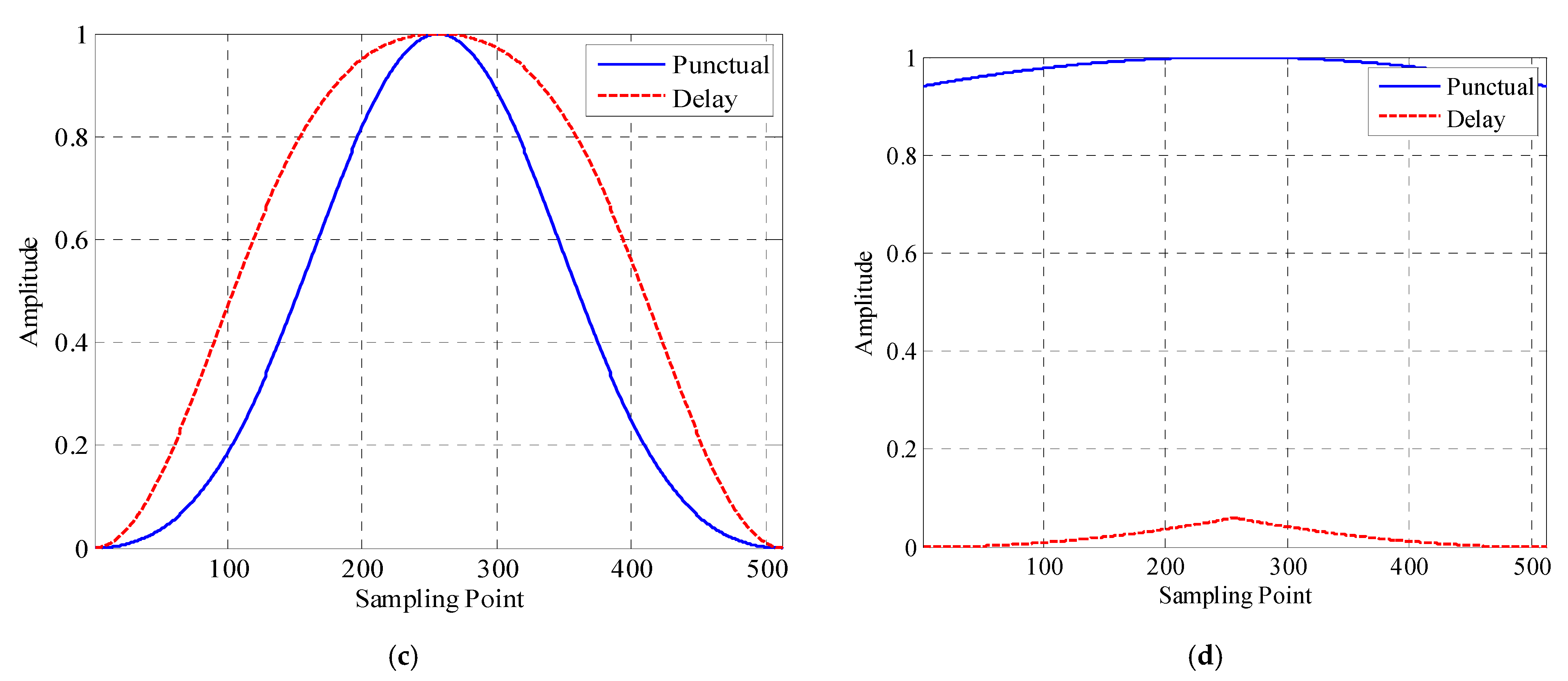
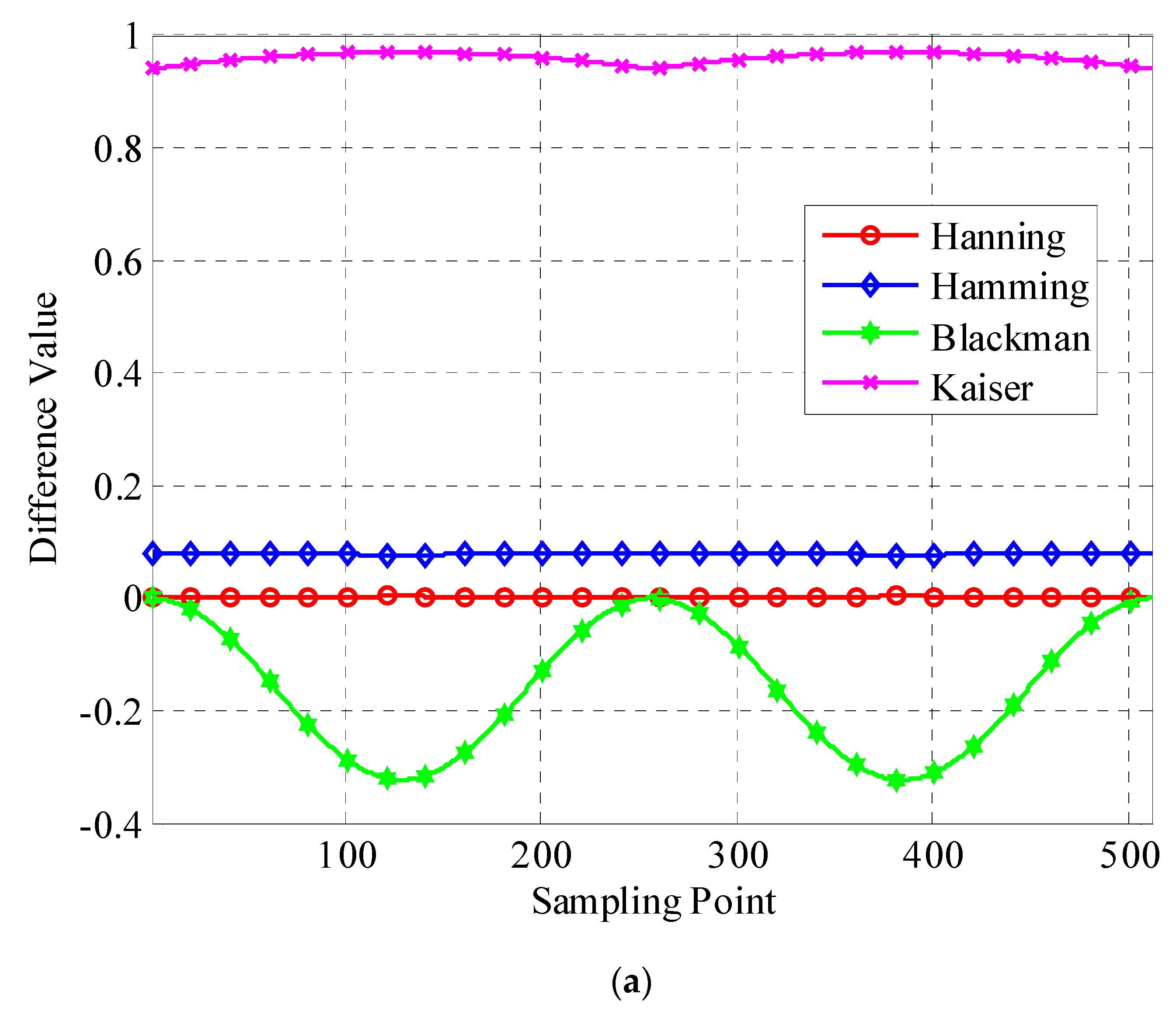
4.3. Simulation Experiment

The five typical window functions of Hanning window, Hamming window, Blackman window, and Kaiser window are taken as examples for simulation analysis. In the simulation experiment, the input is the PRN1 signal of Beidou B3I, the modulation method is BPSK-R(10), and the signal sampling rate is 25 MHz. The effect of the ratio is shown in Figure 15a,b.
The simulation test results show that, whether it is window-PD or window-Lu window function, the effect of 1/2 overlapping windowing on the SNR is very small and can be ignored.

5. Navigation Anti-Jamming Experimental Verification

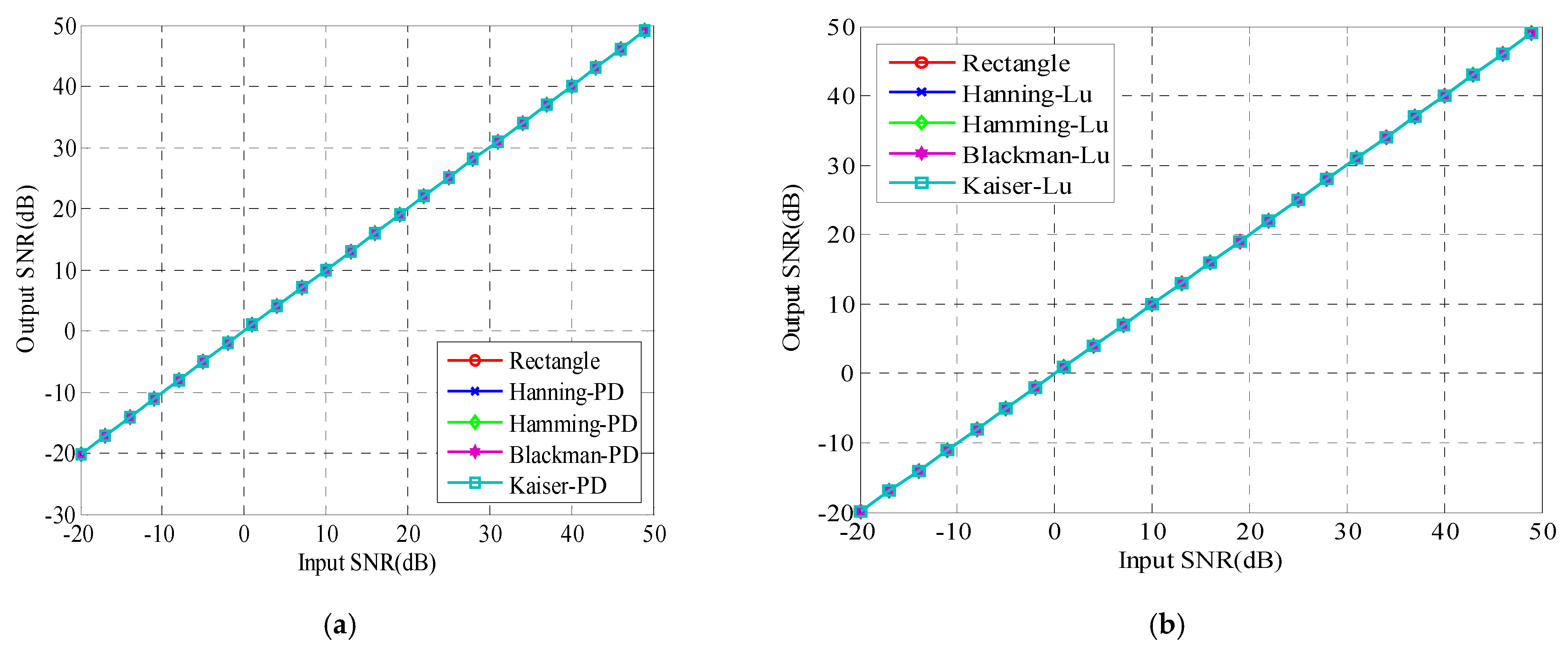
5.1. Simulation Erperiment

5.1.1. Simulation Platform

The simulation verification platform simulates the real navigation receiver signal processing terminal, and its block diagram is shown in Figure 16 The signal adopts PRN1 of Beidou B3I signal, the code of which is 10.23 MHz. In the frequency-domain adaptive anti-jamming simulation, the interference is narrowband interference with a bandwidth of 2 MHz; the receiver bandwidth is 20 MHz, the sampling rate is set to be 25 MHz, and the simulation channel is only a combination of signal, interference and noise. Since the effect of 1/2 overlapping windowing on the signal-to-noise ratio is small, in order to conduct simulation experiments more accurately, when comparing the effects of different window functions in the same experimental scene, the same generated data—including the same signal, interference, and noise—can effectively avoid the inaccuracy of effect evaluation caused by other factors.

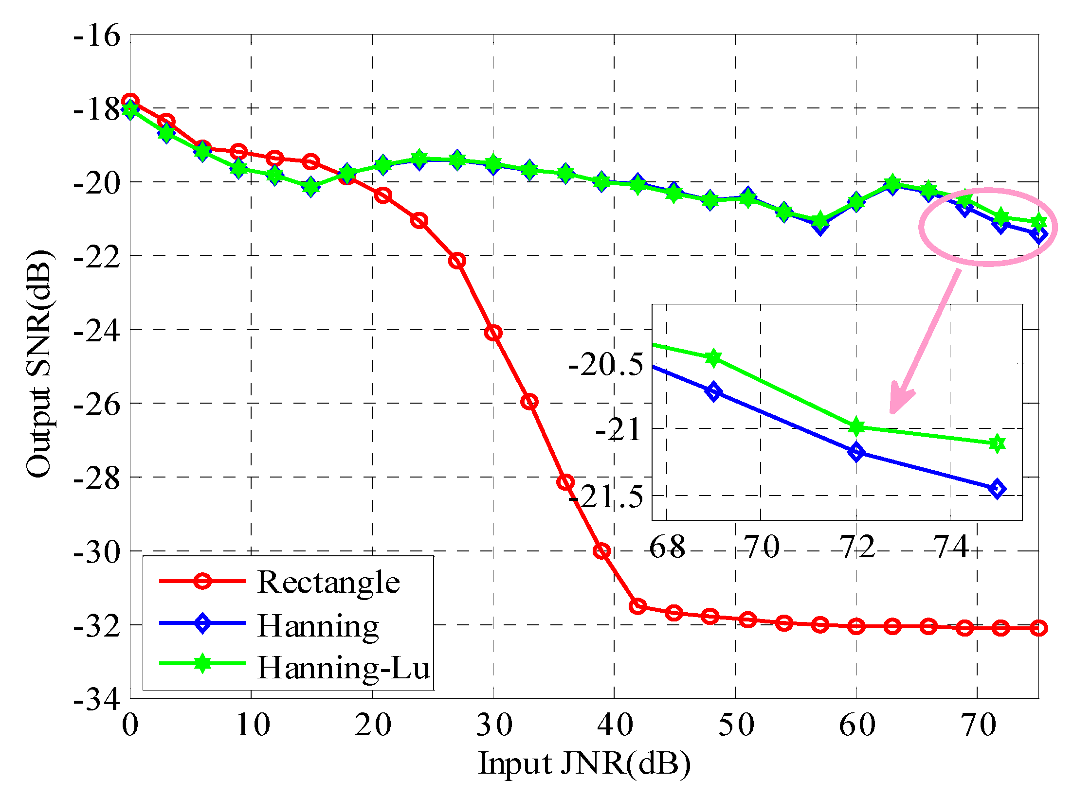
5.1.2. Simulation Verification

Hanning and Hamming are two commonly used window functions in frequency-domain anti-jamming [42]. According to the window function design method proposed in this paper, the proposed Blackman and Kaiser window functions are different from the traditional window functions. Therefore, only Hanning and Hamming window functions are verified in the simulation experiments [44].
It should be noted that the final performance effect of frequency-domain anti-jamming is not only related to the window function, but also to the identification of the interference spectrum. The interference spectrum line estimates the SNR of the primary signal, and the maximum SNR is used as the evaluation value [45].
The SNR of the signal is set to −15 dB, and the jamming-to-noise ratio (JNR) is set to traverse from 0 dB to 75 dB in 3 dB steps. For the Hanning and Hamming window functions, in comparison with the rectangular window and the traditional window function, this paper proposes the window-Lu window function. The influence of the input JNR on the output SNR is shown in Figure 16. The Hanning approach adopted in Figure 17 is the same as the one in Figure 6, the two window functions of which are both traditional Hanning functions.
It can be seen from Figure 16 that when the input JNR is greater than 30 dB, for both the traditional window function and the improved window function proposed in this paper, the output SNR is greater than the rectangular window. This further verifies the positive role played by the window function in frequency-domain anti-jamming. When the JNR is greater than 70 dB, the Hanning-Lu window function proposed in this paper is better than the traditional Hanning window function, and the SNR is improved by about 0.5 dB. Any small SNR loss will affect the energy loss of the navigation system, so a performance improvement of 0.5 dB has a significant impact on the navigation system performance improvement. When the JNR is greater than 30 dB, the Hamming–Lu window function proposed in this paper is significantly better than the traditional Hamming window function. When the JNR is 50 dB, the SNR ratio is improved by more than 3 dB. From the simulation results, the window-Lu window function proposed in this paper has a better effect on the SNR than the traditional window function.

5.2. Exiperiment Verification

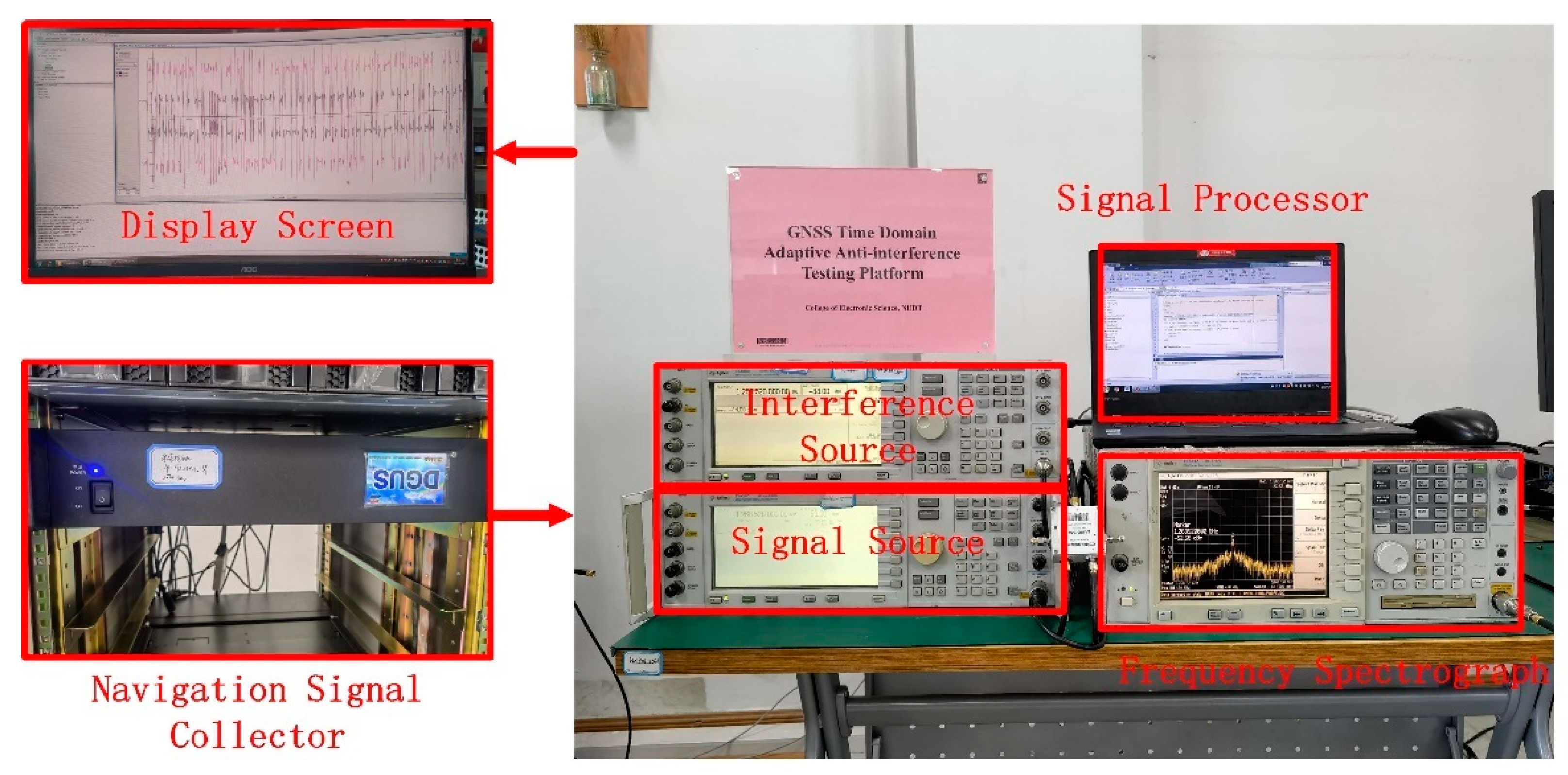
5.2.1. Data Collection Platform

The architecture of the data acquisition platform is similar to the simulation platform. It is designed to simulate the real signal receiving environment, in addition to performing special experiments related to this paper. When collecting data, the interference source emits a narrowband signal. In order to achieve good accuracy of data analysis, the data is preprocessed after data collection. The satellite signal adopts the PRN1 signal of Beidou B3I. The physical object of the data collecting platform is shown in Figure 18.
The evaluation index of the measured data analysis is the same as the simulation analysis, and output SNR is used as the evaluation index.

5.2.2. Measured Data Verification

Verifying the data is the same as the simulation experiment comparing the effect of five window functions (rectangular window, Hanning, Hanning-Lu, Hamming, Hamming-Lu) on frequency-domain anti-jamming. Due to the complexity of collecting data, it is impossible to traverse many scenes as in a simulation experiment. In the verification of the measured data, the SNR is still set to −15 dB, but only the JNR of 20 dB to 70 dB is verified, and the interval is 10 dB. The data analysis method is also the same as the simulation experiment; the experimental results are shown in Figure 19.
It can be seen from Figure 19 that when the JNR is 20 dB, the effects of the five window functions are not significantly different. Starting from the 30 dB JNR, the effect of the rectangular window begins to decrease significantly. When the JNR is greater than 30 dB, the Hamming-Lu window function proposed in this paper is more than 1 dB higher than the traditional Hamming window function, and the maximum is about 2 dB. When the JNR is 70 dB, the Hanning-Lu window function proposed in this paper is about 0.5 dB higher than the traditional Hanning window function.
In general, the window-Lu function proposed in this paper has a smaller impact on the SNR than the traditional window function, and has played a positive role in signal protection, especially under strong interference conditions. The Hanning-Lu window function is recommended for high-interference level situations.

6. Conclusions

In this paper, a window function design method for anti-jamming in the frequency domain of a satellite navigation receiver is proposed, which solves the problem of the traditional window function causing energy loss of the navigation signal. The traditional window function will cause signal loss when overlapping windowing. According to the classic window function, this paper proposes a design method of using two different window functions for overlapping windowing. This method can effectively solve the signal energy loss caused by overlapping windowing. Theoretical analysis shows that typical Hanning window and Hamming window will lead to the loss of signal energy in the application of 1/2 overlapping window. Simulation and measured data show that the traditional window function will cause signal energy loss of about 0.5 dB. The window function design method proposed in this paper will not cause signal energy loss, and is a distortionless window function design method. Although the improvement of the window function does not greatly improve the SNR, it is of great significance in the system level application of satellite navigation. A 0.1 dB performance improvement will improve the signal transmission power and reception sensitivity of the entire system. The method proposed in this paper has been widely used in the Beidou satellite navigation system, achieving good results.

Author Contributions

Z.L. performed the theoretical study, conducted the experiments, processed the data, and wrote the manuscript; J.S. designed the system, provided research suggestions, and revised the manuscript together with L.H.; Z.X. and C.R. helped in performing the experiments; B.L. provided the experiment equipment and suggestions for the manuscript. All authors have read and agreed to the published version of the manuscript.

Funding

This research was supported in part by the Natural Science Foundation of China (NSFC) grants 62003354.

Acknowledgments

The authors would like to thank the editors and reviewers for their efforts in supporting the publication of this paper.

Conflicts of Interest

The authors declare no conflict of interest.

References

  1. Wei, X.; Aman, M.N.; Sikdar, B. Exploiting Correlation Among GPS Signals to Detect GPS Spoofing in Power Grids. IEEE Trans. Ind. Appl. 2022, 58, 697. [Google Scholar] [CrossRef]
  2. Liu, X.; Liu, X.; Yang, Y.; Guo, Y.; Zhang, W. Variational Bayesian-Based Robust Cubature Kalman Filter with Application on SINS/GPS Integrated Navigation System. IEEE Sens. J. 2022, 22, 489. [Google Scholar] [CrossRef]
  3. Collett, I.; Wang, Y.; Shah, R.; Morton, Y.J. Phase Coherence of GPS Signal Land Reflections and its Dependence on Surface Characteristics. IEEE Geosci. Remote Sens. Lett. 2022, 19, 1–5. [Google Scholar] [CrossRef]
  4. Lu, Z.; Chen, F.; Xie, Y.; Sun, Y.; Cai, H. High Precision Pseudo-Range Measurement in GNSS Anti-jamming Antenna Array Processing. Electronics 2020, 9, 412. [Google Scholar] [CrossRef] [Green Version]
  5. Porretta, M.; Schlarmann, B.K.; Ballereau, A.; Crisci, M. A Novel Uplink Scheduling Algorithm for the Galileo System. IEEE Trans. Aerosp. Electron. Syst. 2018, 54, 819. [Google Scholar] [CrossRef]
  6. Tabibi, S.; Geremia-Nievinski, F.; Dam, T. Statistical Comparison and Combination of GPS, GLONASS, and Multi-GNSS Multipath Reflectometry Applied to Snow Depth Retrieval. IEEE Trans. Geosci. Remote Sens. 2017, 55, 3773. [Google Scholar] [CrossRef]
  7. Steiner, L.; Meindl, M.; Marty, C.; Geiger, A. Impact of GPS Processing on the Estimation of Snow Water Equivalent Using Refracted GPS Signals. IEEE Trans. Geosci. Remote Sens. 2020, 58, 123. [Google Scholar] [CrossRef]
  8. Seo, J.; Walter, T. Future Dual-Frequency GPS Navigation System for Intelligent Air Transportation Under Strong Ionospheric Scintillation. IEEE Trans. Intell. Transp. Syst. 2014, 15, 2224. [Google Scholar] [CrossRef]
  9. Li, J.; Pei, X.; Wang, X.; Yao, D.; Zhang, Y.; Yue, Y. Transportation mode identification with GPS trajectory data and GIS information. Tsinghua Sci. Technol. 2021, 26, 403. [Google Scholar] [CrossRef]
  10. Hoseinitabatabaei, S.A.; Gluhak, A.; Tafazolli, R. uDirect: A novel approach for pervasive observation of user direction with mobile phones. In Proceedings of the 2011 IEEE International Conference on Pervasive Computing and Communications (PerCom), Seattle, WA, USA, 21–25 March 2011; pp. 74–83. [Google Scholar] [CrossRef] [Green Version]
  11. Lu, Z.; Nie, J.; Wan, Y.; Ou, G. Optimal reference element for interference suppression in GNSS antenna arrays under channel mismatch. IET Radar Sonar Navig. 2017, 11, 1161–1169. [Google Scholar] [CrossRef]
  12. Guo, Y.; Wu, M.; Tang, K.; Tie, J.; Li, X. Covert Spoofing Algorithm of UAV Based on GPS/INS-Integrated Navigation. IEEE Trans. Veh. Technol. 2019, 68, 6557. [Google Scholar] [CrossRef]
  13. Zhang, J.; Yuan, H. Analysis of unmanned aerial vehicle navigation and height control system based on GPS. J. Syst. Eng. Electron. 2010, 21, 643. [Google Scholar] [CrossRef]
  14. Rezazadeh, N.; Shafai, L. A Compact Microstrip Patch Antenna for Civilian GPS Interference Mitigation. IEEE Antennas Wirel. Propag. Lett. 2018, 17, 381. [Google Scholar] [CrossRef]
  15. Lu, Z.; Nie, J.; Chen, F.; Chen, H.; Ou, G. Adaptive Time Taps of STAP Under Channel Mismatch for GNSS Antenna Arrays. IEEE Trans. Instrum. Meas. 2017, 66, 2813–2824. [Google Scholar] [CrossRef]
  16. Hwang, S.S.; Shynk, J.J. Blind GPS receiver with a modified despreader for interference suppression. IEEE Trans. Aerosp. Electron. Syst. 2006, 42, 503. [Google Scholar] [CrossRef]
  17. Li, X.; Guo, W. Efficient Differential Coherent Accumulation Algorithm for Weak GPS Signal Bit Synchronization. IEEE Commun. Lett. 2013, 17, 936. [Google Scholar] [CrossRef]
  18. Morton, Y.T.; Miller, M.; Tsui, J.; Lin, D.; Zhou, Q. GPS Civil Signal Self-Interference Mitigation During Weak Signal Acquisition. IEEE Trans. Signal Process. 2007, 55, 5859. [Google Scholar] [CrossRef] [Green Version]
  19. Fallahi, K.; Cheng, C.; Fattouche, M. Robust Positioning Systems in the Presence of Outliers Under Weak GPS Signal Conditions. IEEE Syst. J. 2012, 6, 401. [Google Scholar] [CrossRef]
  20. Rignot, E.J.M. Effect of Faraday rotation on L-band interferometric and polarimetric synthetic-aperture radar data. IEEE Trans. Geosci. Remote Sens. 2000, 38, 383. [Google Scholar] [CrossRef] [Green Version]
  21. Meyer, F.J.; Chotoo, K.; Chotoo, S.D.; Huxtable, B.D.; Carrano, C.S. The Influence of Equatorial Scintillation on L-Band SAR Image Quality and Phase. IEEE Trans. Geosci. Remote Sens. 2016, 54, 869. [Google Scholar] [CrossRef]
  22. Vermunt, P.C. Response of Subdaily L-Band Backscatter to Internal and Surface Canopy Water Dynamics. IEEE Trans. Geosci. Remote Sens. 2021, 59, 7322. [Google Scholar] [CrossRef]
  23. Rao, K.D.; Swamy, M.N.S. New approach for suppression of FM jamming in GPS receivers. IEEE Trans. Aerosp. Electron. Syst. 2006, 42, 1464. [Google Scholar] [CrossRef]
  24. Abosekeen, A.; Iqbal, U.; Noureldin, A.; Korenberg, M.J. A Novel Multi-Level Integrated Navigation System for Challenging GNSS Environments. IEEE Trans. Intell. Transp. Syst. 2021, 22, 4838. [Google Scholar] [CrossRef]
  25. Lu, Z.; Chen, H.; Chen, F.; Nie, J.; Ou, G. Blind Adaptive Channel Mismatch Equalization Method for GNSS Antenna Arrays. IET Radar Sonar Navig. 2018, 12, 383–389. [Google Scholar] [CrossRef]
  26. Chien, Y. Design of GPS Anti-Jamming Systems Using Adaptive Notch Filters. IEEE Syst. J. 2015, 9, 451. [Google Scholar] [CrossRef]
  27. Hao, C.; Liu, Y.; Wang, X.; Sun, X. A Modified Anti-Jamming Method Using Dual-Polarized Ellipsoid Minimum Variance Distortionless Response to Predict the Coverage Ratio of Global Positioning System Signal. IEEE Sens. J. 2021, 21, 26839. [Google Scholar] [CrossRef]
  28. Song, J.; Lu, Z.; Xiao, Z.; Li, B.; Sun, G. Optimal Order of Time-Domain Adaptive Filter for Anti-Jamming Navigation Receiver. Remote Sens. 2022, 14, 48. [Google Scholar] [CrossRef]
  29. Li, D.; Liu, J.; Zhao, J.; Wu, G.; Zhao, X. An improved space-time joint anti-jamming algorithm based on variable step LMS. Tsinghua Sci. Technol. 2017, 22, 520. [Google Scholar] [CrossRef]
  30. Huang, L.; Lu, Z.; Xiao, Z.; Ren, C.; Song, J.; Li, B. Suppression of Jammer Multipath in GNSS Antenna Array Receiver. Remote Sens. 2022, 14, 350. [Google Scholar] [CrossRef]
  31. Meng, D.; Feng, Z.; Lu, M. Anti-jamming with adaptive arrays utilizing power inversion algorithm. Tsinghua Sci. Technol. 2008, 13, 796. [Google Scholar] [CrossRef]
  32. Zhou, Z.; Wei, Y. The Influence of Automatic Gain Control on Narrowband Frequency Domain GPS Anti-Jamming Receiver. In Proceedings of the 2021 IEEE 21st International Conference on Communication Technology (ICCT), Tianjin, China, 13–16 October 2021; pp. 497–501. [Google Scholar] [CrossRef]
  33. Wang, L.; Zhao, H.; Xiong, G.; Zhang, S. AM-FM interference suppression for GPS receivers based on time-frequency analysis and synthesis. In Proceedings of the 2005 IEEE International Symposium on Microwave, Antenna, Propagation and EMC Technologies for Wireless Communications, Beijing, China, 8–12 August 2005; pp. 1378–1381. [Google Scholar] [CrossRef]
  34. Lv, W.; Shen, C.; Gui, F.; Tian, Z.; Jiang, D. Real-Time Spectrum Analyzer Based on All Phase FFT Spectrum Analysis. In Proceedings of the 2013 Fourth International Conference on Digital Manufacturing & Automation, Shinan, China, 29–30 June 2013; pp. 966–969. [Google Scholar]
  35. Kim, H.; Jung, I.; Park, Y.; Chung, W.; Choi, S.; Hong, D. Time Spread-Windowed OFDM for Spectral Efficiency Improvement. IEEE Wirel. Commun. Lett. 2018, 7, 696–699. [Google Scholar] [CrossRef]
  36. Chen, K.; Tan, G.; Cao, J.; Lu, M.; Fan, X. Modeling and Improving the Energy Performance of GPS Receivers for Location Services. IEEE Sens. J. 2020, 20, 4512–4523. [Google Scholar] [CrossRef]
  37. Lu, Z.; Nie, J.; Chen, F.; Ou, G. Impact on Anti-jamming Performance of Channel Mismatch in GNSS Antenna Arrays Receivers. Int. J. Antennas Propag. 2016, 2016, 1909708. [Google Scholar] [CrossRef]
  38. Liu, Y.; Hu, H. The Research on GPS Frequency Domain Anti-Jamming Algorithms. In Proceedings of the 2009 5th International Conference on Wireless Communications, Networking and Mobile Computing, Beijing, China, 24–26 September 2009; pp. 1–3. [Google Scholar]
  39. Baggenstoss, P.M. On the Equivalence of Hanning-Weighted and Overlapped Analysis Windows Using Different Window Sizes. IEEE Signal Process. Lett. 2012, 19, 27–30. [Google Scholar] [CrossRef]
  40. Grbić, N.; Knežević, K.; Drajić, D. Analysis of Different Window Function Effects on Doppler Processing in HFSWR Signal Processing. In Proceedings of the 2019 14th International Conference on Advanced Technologies, Systems and Services in Telecommunications (TELSIKS), Nis, Serbia, 23–25 October 2019; pp. 257–260. [Google Scholar]
  41. Jian, L. Strong Interference Supression for Satellite Navigation Receiver with Single Antenna. Ph.D. Thesis, National University and Defence Technology, Changsha, China, 2017. [Google Scholar]
  42. Uyanık, H.; Köseoğlu, M. Performance Evaluation of Different Window Functions for Audio Fingerprint Based Audio Search Algorithm. In Proceedings of the 2020 4th International Symposium on Multidisciplinary Studies and Innovative Technologies (ISMSIT), Istanbul, Turkey, 22–24 October 2020; pp. 1–4. [Google Scholar]
  43. Junwei, N. Study on GNSS Antenna Arrays Anti-jamming Algorithm and Performance Evaluation Key Techniques. Ph.D. Thesis, National University and Defence Technology, Changsha, China, 2012. [Google Scholar]
  44. Jian, D.; Wenwen, Q.; Meng, W. Fast Multi-Objective Optimization of Multi-Parameter Antenna Structures Based on Improved BPNN Surrogate Model. IEEE Access. 2019, 7, 77692–77701. [Google Scholar]
  45. Jian, D.; Qianqian, L.; Lianwen, D. Design of Fragment-Type Antenna Structure Using an Improved BPSO. IEEE Trans. Antennas Propag. 2018, 66, 562–571. [Google Scholar]
Figure 1. Satellite Navigation Receiver Architecture.
Remotesensing 14 01801 g001
Figure 2. Processing diagram of frequency domain anti-jamming.
Remotesensing 14 01801 g002
Figure 3. Typical window function comparison.
Remotesensing 14 01801 g003
Figure 4. Comparison of spectrum before and after windowing. (a) Spectrum before windowing, (b) spectrum after windowing.
Remotesensing 14 01801 g004
Figure 5. Relationship between input and output with different windows.
Remotesensing 14 01801 g005
Figure 6. 1/2 overlapping window processing architecture.
Remotesensing 14 01801 g006
Figure 7. Different window functions and the effect of 1/2 overlapping windowing. (a) Different window function, (b) detailed window of different window functions.
Remotesensing 14 01801 g007
Figure 8. Effect of different window functions on SNR. (a) Performance influence analysis of SNR on output SNR, (b) difference value of difference window, (c) detailed difference value.
Remotesensing 14 01801 g008
Figure 9. Time domain diagram of distortionless delay window function. (a) Hanning window, (b) Hamming window, (c) Blackman window, (d) Kaiser window.
Remotesensing 14 01801 g009aRemotesensing 14 01801 g009b
Figure 10. Difference between punctual and delay window functions. (a) Difference value, (b) detailed difference value.
Remotesensing 14 01801 g010aRemotesensing 14 01801 g010b
Figure 11. 1/2 overlapping windowing effect of different window functions.
Remotesensing 14 01801 g011
Figure 12. Time domain diagram of Window-Lu window function. (a) Hanning, (b) Hamming, (c) Blackman, (d) Kaiser.
Remotesensing 14 01801 g012
Figure 13. Difference value between window-Lu and traditional window. (a) Difference value, (b) detailed difference value.
Remotesensing 14 01801 g013
Figure 14. 1/2 overlapping windowing effect of window-Lu. (a) 1/2 overlapping windowing effect, (b) detailed effect of window-Lu.
Remotesensing 14 01801 g014
Figure 15. Effect of different window functions on the SNR. (a) SNR value in PD with different windows, (b) SNR value in Lu with different windows.
Remotesensing 14 01801 g015
Figure 16. Simulation experiment platform.
Remotesensing 14 01801 g016
Figure 17. Influence of different window functions (simulation).
Remotesensing 14 01801 g017
Figure 18. Data collection platform.
Remotesensing 14 01801 g018
Figure 19. Influence of different window functions (measured).
Remotesensing 14 01801 g019
Publisher’s Note: MDPI stays neutral with regard to jurisdictional claims in published maps and institutional affiliations.

