Article

Low-Cost Single-Frequency DGNSS/DBA Combined Positioning Research and Performance Evaluation

1
College of Mining Engineering, Taiyuan University of Technology, Taiyuan 030024, China
2
State Key Laboratory of Geodesy and Earth’s Dynamics, Innovation Academy for Precision Measurement Science and Technology, Chinese Academy of Sciences, Wuhan 430077, China
3
College of Earth and Planetary Sciences, University of Chinese Academy of Sciences, Beijing 100049, China
*
Author to whom correspondence should be addressed.
Remote Sens. 2022, 14(3), 586; https://doi.org/10.3390/rs14030586
Submission received: 18 December 2021 / Revised: 22 January 2022 / Accepted: 24 January 2022 / Published: 26 January 2022

Abstract

:
In recent years, low-cost single-frequency GNSS receivers have been widely used in many fields such as mass navigation and deformation monitoring; however, due to the poor signal quality of low-cost patch antennae, it is difficult for carrier phase real-time kinematic (RTK) technology to fix the integer ambiguity. Differential GNSS (DGNSS) positioning with pseudorange can effectively meet the high robustness and reliability requirements for the submeter to the meter level positioning accuracy of UVA/vehicle/aerospace users. To improve the DGNSS positioning accuracy and reliability of low-cost single-frequency GNSS receivers in complex environments, we propose a differential barometric altimetry (DBA)-assisted DGNSS positioning algorithm, which solves the DGNSS observation equations jointly and rigorously with the Earth ellipsoidal constraint equations constructed by the DBA altitude. The DBA altitude accuracy at different baseline lengths was evaluated in detail, and the DGNSS positioning performance of the single-frequency low-cost u-blox receiver NEO-M8T with a patch antenna and DGNSS/DBA combined positioning performance with the BMP280 barometer was analyzed by several sets of static and dynamic experiments under different environments. The results show that the single-frequency NEO-M8T receiver with patch antenna DGNSS positioning accuracy is submeter level in the static environment and drops to meter level in the dynamic environment. GPS+BDS dual system has higher positioning accuracy than single GPS or single BDS. DGNSS/DBA combination has higher positioning accuracy than DGNSS, especially the root mean square error (RMSE) can be improved by 30% to 80% in the U direction and slightly improved in the N and E directions. This study can provide an effective solution reference for various applications of low-cost sensor fusion positioning in the mass consumer market.

Graphical Abstract

1. Introduction

With the continuous development and improvement of the Global Navigation Satellite System (GNSS), the number of visible satellites has been greatly increased, which effectively improves the positioning accuracy, reliability, and availability. However, in complex environments such as under trees, urban canyons, tunnels, deep mine pits, and indoors, etc., GNSS signal attenuation is severe, observation quality is poor, or the visible satellites are insufficient and there is the serious multipath effect. These drawbacks will lead to decreased positioning accuracy or even unable to locate, which greatly limit the availability and application of GNSS [1,2]. Combining GNSS with other multi-source sensor technologies to realize the complementary advantages of each system and improve the location-based services (LBS) accuracy of user terminals in harsh scenarios has become a major research hotspot in the field of navigation.
Single-frequency low-cost GNSS receivers, such as u-blox series, SkyTraq S2525F8, etc., are widely used in various industries, providing solutions for surveying and mapping applications [3], landslide deformation monitoring [4,5], pedestrian navigation, vehicle tracking [6], and small unmanned aerial vehicles (UAV) navigation [7]. Low-cost GNSS receivers are smaller in size and mass, but their hardware performance is inferior to that of geodetic GNSS receivers. For example, lower signal-to-noise ratio (SNR), poor observed values, and more frequent satellite out-of-lock and observation data are missing. The main reason is that the observation quality of the low-cost patch antenna is poor. Low-cost GNSS receivers for standard point positioning (SPP) can only obtain meter-level positioning accuracy, which means positioning accuracy and reliability will significantly reduce with positioning errors up to tens of meters in complex urban environments [8]. The single-frequency low-cost u-blox receiver for GNSS RTK positioning has a low fixed rate of carrier phase ambiguity in practical applications due to the poor observed data quality [9].
Compared with GNSS RTK positioning to achieve centimeter-level positioning accuracy, the DGNSS positioning with code pseudorange can only achieve 1–2 m positioning accuracy [10]. However, DGNSS is simpler to implement and can avoid positioning failure caused by RTK ambiguity fixed incorrectly. DGNSS can be widely used in many fields, for example, in the location of mobile devices [11,12], marine navigation, and in coastal navigation and in dynamic vessel positioning [10,13], in hydrography for positioning of acoustic systems [14], in autonomous vehicle positioning [15,16], and civil aviation during precision approach procedures [17]. DGNSS is currently the most widely used augmentation system around the world.
The idea behind DGNSS operation lies in determination of the error related to pseudorange observations and calculated comparing the actual value received by the GNSS receiver and the true value calculated using the satellite and the reference station antenna coordinates. This difference, referred to as a pseudorange correction, is transmitted to users who use a GNSS receiver and take it into account in the positioning process [18]. They can be divided into so-called local-area DGNSS (LADGNSS) services for small areas, such as a relatively small area of several dozen to several hundred square kilometers, and wide-area DGNSS (WADGNSS) services for larger areas such as an entire continent or even worldwide. The positioning accuracy achieved by LADGNSS method is 1–3 m and it decreases with increasing distance between a user and the single reference station [19]. WADGNSS can extend the service area using a few geosynchronous equatorial orbit (GEO) satellites and overcome the error due to the spatial decorrelation, as in, for example, the Wide-Area Augmentation System (WAAS, USA), European Geostationary Navigation Overlay Service (EGNOS, Europe), and MTSAT Satellite Augmentation System (MSAS, Japan). This system is used to obtain a meter-level accuracy over a large region while using a fraction of the number of reference stations [10].
Most studies and analyses of DGNSS positioning with low-cost GNSS receivers have used geodetic antennas. For example, an Flächen Korrektur parameter (FKP)-DGPS algorithm [19] is studied as a new augmentation method for the low-cost GPS receivers by integrating the conventional DGPS correction with the modified FKP correction to mitigate the positioning error due to the spatial decorrelation. Single-frequency DGPS aided low-cost inertial navigation system (INS) positioning [20] was studied to achieve the real-time high-frequency state output with decimeter position accuracy and centimeter velocity accuracy. However, there is still little research on DGNSS for low-cost GNSS receivers with low-cost patch antenna and fusion positioning with other low-cost sensors.
Height constraint is an effective method to improve the GNSS positioning accuracy, for example, due to the insufficient number of available satellites, the BDS-1 has used electronic maps as height constraints to improve the users’ positioning accuracy [21]. This method is more complicated to implement and it is difficult to promote its application. The barometric altimetry is low-cost, independent of environmental restrictions, and can be used both indoors and outdoors. Low-cost barometer altimetry-assisted GNSS positioning navigation is also widely used in the field of aviation flights and smartphone navigation, etc. [22,23,24,25]. The basic principle of barometric altimetry is to use the physical phenomenon that the atmospheric pressure on the Earth’s surface gradually decreases with increasing height, but, due to the irregular changes of atmospheric pressure, the altitude error directly calculated by a single barometer is as high as tens or even hundreds of meters, which cannot be used as a constraint to improve GNSS positioning accuracy. Similar to DGNSS, the accurate height can be obtained by barometric correction compensation or differential barometric altitude (DBA). That is, using the property that local atmospheric pressure changes are similar, a barometer is placed at the reference station and another barometer is used as a mobile station to determine its high-precision relative altitude by the differential equation. The altitude accuracy and reliability obtained by DBA mode are high, which can effectively constrain other technology to improve positioning and navigation accuracy.
The user altitude obtained by the DBA system was applied as a virtual satellite in the China Area Positioning System (CAPS), and the construction of independent earth ellipsoidal constraint equations by users’ altitude can effectively solve the insufficient number of CAPS satellites and improve its 3D positioning accuracy and availability [26,27,28]. The DBA system also be applied to mobile cellular network positioning for accurately determining the user’s height, and reduced 3D positioning to planar positioning which can obtain more desirable positioning accuracy [29]. Mobile cellular base stations can be used as DBA reference stations and transmitted the relevant atmosphere pressure data to the user side through mobile communication networks, achieving GNSS SPP/DBA combined 3D positioning with the altitude accuracy better than 1 m [30]. Inertial/barometric altitude can be fused to measure vertical velocity and height with velocity root mean squared error (RMSE) between 0.04 to 0.24 m/s and RMSE in height between 5 to 68 cm [31]. In addition, a barometer installed on a wearable device can measure vital signs such as blood pressure by detecting the position and orientation of the human body, thus providing a better telemedicine solution for precision medicine [32,33].
At present, to our knowledge, little research has been reported on the DGNSS/DBA combined positioning with low-cost GNSS receivers and a patch antenna, and there is also a lack of research and analysis on the theoretical methods and application effects of DBA, which is worth further study. In this study, we firstly propose a DGNSS/DBA combined positioning algorithm. Second, the DBA altitude accuracy at different baseline lengths is evaluated in detail. Then, the DGNSS performance of single-frequency low-cost NEO-M8T receiver and the accuracy and reliability of DGNSS/DBA combined positioning with low-cost BMP280 barometer are fully evaluated through actual measurement data.
This manuscript is organized as follows: Section 1 is the introduction. Section 2 is the mathematical model of DGNSS/DBA combined positioning, which contains Section 2.1 about DGNSS positioning observation equations; Section 2.2 about the principle of the DBA system; and Section 2.3 on the DGNSS/DBA combined positioning algorithm. Section 3 reports the experiment results, containing Section 3.1 that introduces experimental data; Section 3.2 about DBA altitude accuracy evaluation at different baseline lengths; Section 3.3 and Section 3.4 on the DGNSS/DBA combined static and kinematic vehicle positioning performance evaluation for the single-frequency low-cost NEO-M8T receiver and BMP280 barometer, respectively. Section 4 presents the discussions. Section 5 is the conclusion.

2. Mathematical Model of DGNSS/DBA Combined Positioning

2.1. DGNSS Positioning Observation Equation

GNSS receivers can simultaneously receive observation data such as code pseudorange, carrier phase, Doppler shift, and SNR. The raw observation values contain the receiver geometric position parameters, clock error as well as hardware delays parameters, and various error corrections, such as tropospheric errors and ionospheric errors. Therefore, the raw code pseudorange observation equation between satellite s and receiver i can be expressed as:
P i s = ρ i s + c ( d t i d t s ) + I i s + T i s + M i s + ε i s
where P i s denotes the code pseudorange observation between satellite s and receiver i (Unit: m); ρ i s = ( X s X ) 2 + ( Y s Y ) 2 + ( Z s Z ) 2 denotes the geometric distance between satellite s and receiver i at the moment of signal transmission, ( X s , Y s , Z s ) and ( X , Y , Z ) are the satellite s and unknown receiver i antenna center position. c is the speed of light in vacuum; d t i denotes the receiver clock error; d t s denotes the satellite clock error; I i s is the ionospheric error; T i s is the tropospheric error; M i s is the multipath delay error; ε i s contains the code pseudorange measurement noise and other uncorrected errors.
For the short and medium baselines, the receiver clock error and satellite clock error are eliminated in the double-difference observation equation, the ionospheric and tropospheric errors can be neglected, and the DGNSS observation equation can be simplified and expressed as [34]:
Δ P i , j s 1 s k = Δ ρ i , j s 1 s k + Δ ε i , j s 1 s k
where Δ denotes the double-difference operator; i and j denotes the reference station receiver and mobile receiver; s 1 and s k denote the reference and nonreference satellite, respectively.

2.2. Principle of the DBA System

Single-barometer altimetry affected by atmospheric temperature, seasonal changes, and other factors drifts up to several tens of meters within a day, with poor stability and reliability [35]. Due to the Earth’s gravitational field, the space atmosphere pressure and height show a certain regular distribution. Except for the local strong convection zone, the trend of atmospheric pressure variation in the local range of several tens of kilometers shows the same physical characteristics, and the atmosphere is basically in hydrostatic equilibrium in the vertical direction. Usually, the atmospheric pressure is distributed more evenly in the horizontal direction, and the pressure difference is about 1 hPa at a distance of 100 km. Thus, the concept of “difference” can be extended to the field of barometric altimetry with the help of differential GNSS positioning, that is, by setting one (or several) barometric reference points, the barometric altimetry value of the mobile station can be corrected by the precise altitude of the reference station to compensate the influence of atmospheric physical environment changes on the altitude measurement results of the mobile station, thus improving the accuracy of the user altitude of the mobile station.
When the barometric reference station and the mobile station are within a few tens of kilometers, their latitude, gravitational acceleration, and water vapor factors have the same effect on the atmospheric pressure, so the above three errors can be neglected to obtain the simplified DBA formula [36]:
h = h 0 + 18,410 ( 1 + t m 273.15 ) lg P 0 P
where h is the altitude of the mobile station to be found, h 0 is the known altitude of the reference station, P 0 is the pressure of the reference station, P is the pressure of the mobile station, and t m is the average Celsius temperature between the reference station and the mobile station.

2.3. DGNSS/DBA Combined Positioning Algorithm

In this study, we propose a DGNSS/DBA combined positioning algorithm, in which the user’s altitude obtained by the DBA system in Section 2.2 is used to construct the Earth ellipsoid constraint equation and solved rigorously as an independent observation jointly with the DGNSS observation equation, which is equivalent to adding a virtual satellite located at the center of the Earth [26]. Since the geodetic height is an independent variable in GNSS coordinates, an approximate ellipsoid with the altitude h from the reference ellipsoid (WGS-84) can be constructed using the user geodetic height, as shown in Figure 1.
At this time, when the ground user’s geodetic height is not very large, the observation equation after DGNSS/DBA combination can be expressed as:
{ Δ P i , j s 1 s k = Δ ρ i , j s 1 s k + Δ ε i , j s 1 s k X 2 + Y 2 ( a + h ) 2 + Z 2 ( b + h ) 2 = 1
the symbols in the DGNSS observation equation in the first line of Equation (4) are the same as Equation (2). P ( X , Y , Z ) is the 3D coordinate of the ground user; a and b are the long and short semiaxes of the WGS-84 Earth reference ellipsoid, respectively. Since h is much smaller than the long and short semiaxes of the Earth reference ellipsoid, an approximate reference ellipsoid with a long semiaxis a + h and short semiaxis b + h is used instead without causing much bias [37]. To solve the Earth ellipsoid constraint equation in the second expression of Equation (4) by differential processing, the ellipsoid constraint equation is expanded in the user’s approximate position ( X 0 , Y 0 , Z 0 ) according to the Taylor series, and only the first-order term is retained, where the partial derivative of X is obtained as:
2 X 0 ( a + h ) 2 d X 2 X 0 2 ( a + h ) 3 d h 2 Y 0 2 ( a + h ) 3 d h 2 Z 0 2 ( b + h ) 3 d h = 0
after simplification, we get:
h X 0 = X 0 ( a + h ) ( b + h ) 3 ( X 0 2 + Y 0 2 ) ( b + h ) 3 + Z 0 2 ( a + h ) 3
similarly, taking partial derivatives of Y and Z yields:
h Y 0 = Y 0 ( a + h ) ( b + h ) 3 ( X 0 2 + Y 0 2 ) ( b + h ) 3 + Z 0 2 ( a + h ) 3
h Z 0 = Z 0 ( a + h ) 3 ( b + h ) ( X 0 2 + Y 0 2 ) ( b + h ) 3 + Z 0 2 ( a + h ) 3
let α = h / X 0 , β = h / Y 0 , γ = h / Z 0 , that is, the Earth ellipsoidal constraint equation in Equation (4) is linearized at the approximate coordinates ( X 0 , Y 0 , Z 0 ) to give:
V D B A = α d X + β d Y + γ d Z d h
where d h = h h ^ is the altitude residual, h is the altitude obtained by the DBA system, and h ^ is the geodetic height obtained by the users’ at the approximate position. d X , d Y , d Z are positional corrections of the receiver antenna center. The detailed conversion process can be found in the original literature [38].
Similarly, the DGNSS observation equation in the first expression of Equation (4) is expanded by the Taylor series at the approximate position ( X 0 , Y 0 , Z 0 ) , omitting higher-order terms above the first order, and combined with Equation (9) to obtain the DGNSS/DBA combined positioning error equation:
V = H x ^ l , P
in Equation (10), the parameter estimated as x ^ = [ d X d Y d Z ] T contains three approximate position correction values; V = [ V 1 V i V D B A ] T is the residual vector, H = [ l 1 m 1 n 1 l i m i n i α β γ ] is the coefficient matrix, l i = ( X s X 0 ) ρ j ( 0 ) s ( X k X 0 ) ρ j ( 0 ) k , m i = ( Y s Y 0 ) ρ j ( 0 ) s ( Y k Y 0 ) ρ j ( 0 ) k , n i = ( Z s Z 0 ) ρ j ( 0 ) s ( Z k Z 0 ) ρ j ( 0 ) k are the pseudorange double-difference directional cosine, respectively. l = [ L 1 L i d h ] T are the observation value vectors. P = [ P D G N S S 0 0 P D B A ] is the DGNSS/DBA combined positioning weight matrix. P D G N S S = Q D D 1 is the a priori weight matrix of GNSS pseudorange double-difference observation equation. Q D D is the GNSS pseudorange double-difference observation values covariance matrix, the stochastic model of GNSS nondifferential observations adopts the sine trigonometric function elevation angle fixed-weight model [39]. According to the error propagation law, the GNSS relative positioning variance-covariance matrix can be expressed as Q D D [34]. The a priori weight P D B A of the DBA can be determined based on the results of the empirical evaluation in Section 3.2. We can solve Equation (10) using the single-epoch weighted least squares method, as Equation (11):
{ x ^ = ( H T P H ) 1 H T P l Q x ^ x ^ = ( H T P H ) 1
where Q x ^ x ^ is the posterior covariance matrix of the parameter x ^ . It can be found that the DBA altitude constraint is equivalent to adding a code pseudorange observation, and the condition number of the error equation coefficient matrix H becomes significantly better, the position dilution of precision (PDOP) value can be effectively reduced. However, the accuracy of the positioning solution is influenced by the accuracy of DBA altitude, i.e., if the accuracy of DBA altitude is better than DGNSS altitude, the improvement effect is obvious, otherwise, the positioning accuracy cannot be improved.

3. Experiment Results

3.1. The Introduction of Experiment Data

In the experiment, the reference station included a high-precision geodetic GNSS receiver Trimble NET R9, a Trimble Choking 59,800 antenna, and a low-cost BMP280 barometer. The mobile station consisted of a single-frequency low-cost u-blox receiver NEO-M8T, a patch antenna, and two BMP280 barometers. The mobile station was also equipped with a geodetic receiver Trimble NET R9 for data acquisition, and the postprocessed kinematic (PPK) mode of commercial software Inertial Explorer 8.70 was used to process data to obtain high-precision 3D coordinate sequences as reference values. The nominal resolution of the low-cost BMP280 barometer was 0.01 mbar (0.1 m) and the data sampling rate was set at 1 Hz. As shown in Figure 2, to prevent the effect of crosswind on the barometric pressure, the barometer was placed inside a transparent plastic box with several small holes at the top of the box. All experimental data were recorded and postprocessed by a laptop computer. The height deviation of the BMP280 barometer from the GNSS antenna phase center was compensated by data preprocessing, and the DGNSS/DBA combined positioning analysis was performed by the self-written programs.
The whole experiment was divided into three parts. The first experiment was used to evaluate the DBA altitude accuracy at different baseline lengths and to provide a priori information for subsequently combined positioning with DGNSS. The second experiment evaluated the positioning performance of low-cost single-frequency DGNSS and DGNSS/DBA combined positioning through static experiments with 65 m and 6.0 km baseline lengths. The third experiment evaluated the kinematic vehicle positioning performance of low-cost single-frequency DGNSS and DGNSS/DBA combined positioning in open and complex urban environments, respectively.

3.2. DBA Altitude Accuracy Evaluation at Different Baseline Lengths

The altitude accuracy and practical range obtained by the BMP280 barometer DBA model were evaluated through different baseline lengths outdoors. The experimental data were collected on 18 September 2020, and Figure 2 shows the hardware equipment of the reference station and mobile stations. The reference station was arranged on the observation pier on the roof of the Innovation Academy for Precision Measurement Science and Technology, Chinese Academy of Sciences (APM, CAS). Figure 3 shows five different mobile station locations at baseline lengths of 0 m, 65 m, 2.6 km (shopping mall plaza), 6.0 km (Wufu Plaza on the Yangtze River), and 10.0 km (the roof of the PET center of Tongji Medical College), with a data acquisition time of about 30 min for each static point. Figure 4 and Table 1 show the time series and RMSE accuracy statistics of the altitude results of the DBA system under five groups of different baseline lengths.
In Table 1, DBA_min and DBA_max denote the minimum and maximum altitude results obtained by the DBA model. Mean and STD denotes the average value of DBA altitude and standard deviation. As can be seen from Figure 4 and Table 1, the outdoor DBA altitude RMSE increased gradually with an increase of baseline length, and the DBA altitude RMSE was submeter level within the 2 km baseline length and did not exceed 2 m within the 10 km baseline length. This result can provide a priori information to determine the weight matrix P D B A in Equation (11) for the DGNSS/DBA combined positioning.

3.3. DGNSS/DBA Combined Static Positioning Results

This section mainly evaluates the static positioning performance of the single-frequency low-cost NEO-M8T receiver and BMP280 barometer DGNSS/DBA combined positioning algorithm. The experimental data were consistent with Section 3.2, and the 65 m and 6.0 km baseline length data were selected for processing and analysis. Two data processing modes, DGNSS and DGNSS/DBA, were set, and each mode was divided into single GPS, single BDS, and GPS+BDS dual systems by the satellite system.

3.3.1. Baseline Length 65 m

This experiment used 65 m short baseline static data and performed statistical analysis by setting the elevation mask angle from 10 to 40 degrees, and the prior error of the DBA system was σ D B A = 1.0   m . Table 2 shows the average number of visible satellites at different elevation mask angles, and Table 3 lists the average PDOP values for DGNSS and DGNSS/DBA modes at different elevation mask angles.
As can be seen from Table 2, the average number of visible satellites was seven to eight for GPS and 12 to 14 for BDS at a low elevation mask angle of 10 or 20 degrees. With the increase of the elevation mask angle, the number of available satellites of both GPS and BDS systems decreased significantly, the satellite space geometry distribution became worse, and the PDOP value gradually increased. The number of GPS satellites was only three at the elevation mask angles of 40 degrees, and the user receiver could not be positioned at this time, while the number of visible satellites of BDS in the China region was larger with eight to 10 visible satellites at the elevation mask angles of 30 or 40 degrees. The GPS+BDS dual system significantly increased the number of visible satellites compared to the single system, which significantly improved the satellite geometry and reduced the PDOP value. As shown in Table 3, increasing a DBA observation was equivalent to adding a virtual satellite, which improved the satellite geometry distribution and reduced the PDOP value; and the reduction of PDOP value was more significant in the environment with a higher elevation mask angle. When the elevation mask angle was 40 degrees, three GPS satellites could not complete the positioning, and adding a DBA observation ensured the availability of user receiver positioning. Figure 5, Figure 6, Figure 7 and Figure 8 show the north (N)/east (E)/up (U) direction deviation sequence of the two data processing modes at the elevation mask angle 10 to 40 degrees. Each mode included single GPS, single BDS, and a GPS+BDS dual system. Table 4 shows the RMSE values in the N/E/U directions for the two data processing modes at different elevation mask angles.
Table 2, Table 3 and Table 4 and Figure 5 show that due to sufficient number of visible satellites and low PDOP values at the elevation mask angle of 10 degrees, the positioning accuracy of the DGNSS mode in the N/E/U directions could reach the decimeter to submeter level, and the RMSE of single GPS and single BDS in the N/E/U directions were 0.82/0.53/1.32 m and 0.72/0.96/1.08 m, respectively. In DGNSS/DBA mode, the RMSE of GPS/DBA and BDS/DBA in the N/E/U directions were 0.76/0.52/0.89 m and 0.69/0.96/0.63 m, respectively, which were 30% to 40% better than DGNSS in the U direction and slightly better in N and E directions. Due to the increase of available observations and better satellite geometry of the GPS+BDS dual system, the RMSE of DGNSS and DGNSS/DBA mode in the N/E/U directions were 0.58/0.61/0.94 m and 0.57/0.60/0.57 m, respectively. Both had some improvements over the single system. The results at the elevation mask angle of 20 degrees were similar to that of 10 degrees.
Table 2, Table 3 and Table 4 and Figure 7 show that the PDOP value became larger due to the fewer available observation satellites and worse satellite geometry at the elevation mask angle of 30 degrees, and the RMSE in the N/E/U directions became significantly larger than that of 10 and 20 degrees. The RMSE in the N/E/U directions were 1.24/0.99/4.81 m and 1.33/0.93/2.85 m for single GPS and single BDS, and 0.71/0.56/1.47 m for GPS+BDS dual system in DGNSS mode, respectively. Compared with the DGNSS mode, the accuracy of the N/E/U directions was significantly improved by the DGNSS/DBA combination, and the RMSE of GPS/DBA and BDS/DBA in the N/E/U directions were improved by 6.4%/40%/77.3% and 29.3%/20.4%/66.6%, and the RMSE of GPS+BDS/DBA combination in the N/E/U directions were improved by 8.5%/25%/45.6%.
When the elevation mask angle was 40 degrees, the number of available satellites for single GPS was three and they could not be located. The RMSE of single BDS was 2.21/1.23/5.81 m in the N/E/U directions, and 0.89/0.85/3.07 m for the GPS+BDS dual system (Table 2, Table 3 and Table 4 and Figure 8). In DGNSS/DBA mode, GPS/DBA met the most basic positioning requirements for four satellites and the RMSE in the N/E/U directions was 1.23/1.08/1.02 m; the RMSE of BDS/DBA in the N/E/U directions was improved by 44.3%/12.2%/82.4%, and the RMSE of the GPS+BDS/DBA combination in the N/E/U directions was improved by 33.7%/0%/60.9%, respectively.

3.3.2. Baseline Length 6.0 km

In this experiment, static data with 6.0 km baseline length were processed and analyzed, the elevation mask angle was 10 degrees, and the priori error of the DBA system was σ D B A = 1.5   m . Figure 9 shows the number of GNSS visible satellites and the PDOP value sequence for both DGNSS and DGNSS/DBA modes at the baseline length of 6.0 km. The RMSE accuracy statistics and corresponding deviation sequence in the N/E/U directions for the DGNSS and DGNSS/DBA mode are shown in Table 5 and Figure 10, respectively.
Table 5 and Figure 9 and Figure 10 show that the PDOP value of BDS was smaller than GPS in the China region due to a large number of observable satellites. The RMSE of single BDS in the N/E/U directions was 0.61/2.27/2.64 m, which was better than that of single GPS in DGNSS mode (2.23/1.12/4.41 m). The RMSE of the GPS+BDS dual system in the N/E/U directions was 0.60/1.01/2.22 m with higher positioning accuracy than single system. Compared to DGNSS mode, the RMSE in the U direction of DGNSS/DBA mode reduced by 0.5 m and 0.1 m for single GPS and single BDS, and there was also some improvement in the N and E directions. However, the GPS+BDS dual system did not improve significantly, due to the higher DGNSS accuracy and the lower DBA height accuracy at 6.0 km baseline length did not prove to be an obvious constraint.

3.4. DGNSS/DBA Combined Kinematic Vehicle Positioning Results

In this section, two kinematic vehicle experiments were designed to evaluate the dynamic positioning performance of the single-frequency low-cost NEO-M8T receiver and the BMP280 barometer DGNSS/DBA combined positioning algorithm.
The site photo of the mobile station equipment of the kinematic vehicle experiment is shown in Figure 11. The platform contained four multisystem dual-frequency geodetic GNSS antennas which were connected to Trimble Net R9 receivers to obtain the high precision reference value. The single-frequency, low-cost u-blox NEO-M8T receiver, a patch antenna and a BMP280 barometer were laid on the roof of the car. Two sets of kinematic vehicle data were collected, the first set was located in an open urban environment and the second set was in a complex urban environment.

3.4.1. Open Urban Environment

This experiment was collected near the industrial park in Caidian District, Wuhan, China, on 20 November 2020, with a data duration of about 80 min. The area has an open urban environment with less shading and good data quality. Figure 12 shows the kinematic vehicle experiment test scene and test trajectory in the open urban environment. Figure 13 shows the number of GNSS visible satellites and the sequence of PDOP values during the kinematic vehicle experiment.
As can be seen in Figure 13, the number of observable satellites of GPS and BDS fluctuated greatly for the kinematic vehicle, resulting in a significant increase in PDOP values compared to a static environment. The addition of DBA observations significantly improved the satellite geometric spatial distribution and reduced the PDOP values. In the open urban environment kinematic vehicle experiment, the comparison of the low-cost BMP280 barometer DBA altitude with the Trimble NET R9 reference altitude is shown in Figure 14. It can be seen that the BMP280 barometer DBA altitude had a high consistency with the reference altitude with an RMSE of 2.10 m. This value can be used to set the a priori weight matrix in the DGNSS/DBA combined positioning process.
The RMSE statistical results and deviation sequence in the N/E/U directions for both DGNSS and DGNSS/DBA modes are given in Table 6 and Figure 15, respectively. The RMSE values of single GPS and single BDS in the N/E/U directions were 1.20/1.32/3.18 m and 1.58/2.11/5.02 m for DGNSS mode, respectively. The GPS/DBA, BDS/DBA, and GPS+BDS/DBA modes improved the RMSE by 40% to 60% in the U direction and increased slightly in the N and E directions, and the DBA altitude showed a good constraint effect.

3.4.2. Complex Urban Environment

This experiment was collected in Wuchang District, Wuhan, China, on November 20, 2020, with a valid data duration of about 1 h. The area is a complex urban environment, and the occlusion is relatively serious. Figure 16 shows kinematic vehicle experiment test scene and test trajectory in the complex urban environment. Figure 17 shows the number of visible GNSS satellites and the sequence of PDOP values during the kinematic vehicle experiment, and it can be seen that compared with the open urban environment, the number of GNSS visible satellites of the kinematic vehicle in the urban environment was significantly lower and the PDOP values became larger.
Figure 18 shows the DBA altitude results of the low-cost BMP280 barometer during the kinematic vehicle experiment in the complex urban environment compared to the Trimble Net R9 reference altitude. It can be seen that the DBA altitude in the complex urban environment was also very consistent with the reference altitude with an RMSE of 2.19 m, which is approximately the same as the RMSE results of the DBA altitude in the open urban environment in Section 3.4.1. It indicates that the DBA altitude accuracy was reliable and stable in different environments, and could assist GNSS to improve the positioning accuracy in the complex urban environment.
The RMSE statistics and deviation sequence of the single-frequency, low-cost u-blox NEO-M8T and the geodetic Trimble Net R9 receiver for both DGNSS and DGNSS/DBA modes in the N/E/U directions are given in Table 7 and Figure 19 and Figure 20. The RMSE of the low-cost u-blox NEO-M8T receiver with single GPS and single BDS in DGNSS mode were 4.33/4.69/8.35 m and 4.91/6.91/19.48 m in the N/E/U directions, respectively, and the RMSE of the GPS+BDS dual system was 3.28/5.23/8.91 m. The RMSE statistics of the geodetic Trimble Net R9 receiver in N/E direction in the complex urban environment was maintained at submeter level; the U direction was relatively poor, with RMSE not exceeding 2.7 m. The difference of RMSE between the two GNSS receivers in 3D directions was determined by their hardware performance. Compared with DGNSS mode, the RMSE of single GPS, single BDS, and GPS+BDS dual system in DGNSS/DBA mode of low-cost NEO-M8T receiver slightly worsened in the N and E directions, while the RMSE in U direction could be improved by 50% to 80%, and this improvement ratio is higher than that in the open urban environment. Similarly, for the geodetic Trimble Net R9 receiver, the RMSE of the DGNSS/DBA combination remains the same in the N/E directions compared to DGNSS mode, and the RMSE in the U direction could be improved by 30% to 60%, which verifies the advantage of DBA altitude in assisting DGNSS positioning.
It can also be seen that when comparing Table 3, Table 4 and Table 5 for the static experiment with Table 6 and Table 7 for the kinematic experiments, a low-cost receiver with only BDS signals provided lower RMSE values than GPS in static experiments, which was mainly due to BDS having more observation satellites and the PDOP value being lower than GPS at this time. In open and complex urban kinematic experiments, as shown in Figure 13 and Figure 17, BDS had very large fluctuations for the number of observable satellites and a larger average PDOP value (3.02 and 4.10) than GPS (1.97 and 3.16) for both cases. This is the main reason that a low-cost receiver with only GPS signals provides lower RMSE values than with BDS in kinematic experiments.

4. Discussion

As the low-cost single-frequency GNSS receivers dominate most of the GNSS market [40], there is a strong interest in enhancing their accuracy. Low-cost DBA altitude plays a significant constraining role in improving the DGNSS positioning accuracy.
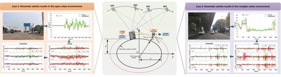
In the DBA altitude accuracy evaluation experiment, BMP280 barometers can achieve better than 2 m altitude accuracy within 10 km baseline lengths in static environments. The DBA altitude consistent with GNSS reference altitude in Figure 14 and Figure 18 implies that it is also reliable and stable in complex environments. Low-cost single-frequency GNSS receivers with a patch antenna have become increasingly popular due to their lower and lower price. The DGNSS positioning accuracy of single-frequency low-cost GNSS receivers can still meet the submeter positioning accuracy needed by the general public in GNSS-friendly environments. However, the RMSE in the N/E/U directions are all at the meter-level in complex urban environments since low-cost GNSS receivers have poor observation quality, and the positioning accuracy of GPS+BDS dual system is significantly improved compared to single system. There is only a single-epoch resolution algorithm rather than a filtering algorithm is used in this study. In the future, with more and more satellites available for low-cost GNSS receivers and the use of multiple filtering algorithms, DGNSS positioning accuracy is expected to be further improved.
The DGNSS/DBA combined positioning can effectively improve the DGNSS positioning accuracy and meet the demand for real-time positioning applications. The Earth ellipsoid constraint equation constructed by the DBA altitude is equivalent to adding a virtual satellite located at the center of the Earth, effectively improving the spatial geometry structure of the observation satellite. The DGNSS/DBA combined positioning improves the positioning accuracy in the U direction by 30% to 80% compared with the DGNSS positioning, while the positioning accuracy in N and E directions also has a certain improvement effect.
Nowadays, most smartphones integrate both an inexpensive GNSS chip and a barometric pressure sensor. WADGNSS services [10] and a large number of meteorological stations [26] can provide correction information to users. We can achieve higher positioning accuracy without increasing hardware costs. The applications of low-cost DGNSS/DBA, such as indoor and outdoor seamless switching positioning, car navigation, emergency mapping, LBS, and rescue, etc. are likely to increase dramatically. Subsequently, based on the combined positioning of low-cost DGNSS/DBA, the positioning performance research by integrating other sensors, such as MEMS IMU and geomagnetic, etc., will be worth further investigation.

5. Conclusions

In this study, low-cost single-frequency DGNSS/DBA combined positioning research and performance evaluation was carried out. First, a DGNSS/DBA combined positioning model is proposed. The Earth ellipsoid constraint equation act as a virtual satellite observation at the center of the Earth, effectively improving the spatial geometry structure and PDOP value of the observation satellite. The low-cost BMP280 barometer DBA altitude accuracy is evaluated by different baseline lengths, which is better than the submeter level within 2 km and better than 2 m within 10 km baseline length. In both open and complex urban environment kinematic vehicle experiments, the DBA altitude accuracy is better than 2.20 m, which indicates that the DBA system has highly reliable and stability in different environments in local area.
The low-cost single-frequency NEO-M8T receiver with a patch antenna can achieve submeter level positioning accuracy for DGNSS positioning in the N/E directions and better than 1.5 m in the U direction in a short baseline static environment; as the baseline length increases, the DGNSS positioning accuracy gradually decreases. The positioning accuracy in a kinematic vehicle environment is significantly lower than in the static environment, and the RMSE in the N/E/U directions are all at the meter level in the complex urban environment, and the positioning accuracy of both GPS+BDS dual system is significantly improved compared to single system. The DGNSS/DBA combined positioning for low-cost NEO-M8T receiver and BMP280 barometer improves the positioning accuracy in the U direction by 30% to 80% compared with the DGNSS positioning, while the positioning accuracy in the N and E directions also has a certain improvement effect.

Author Contributions

Conceptualization, S.W.; methodology, S.W.; software, S.W., M.G., W.Z., D.L. and S.C.; validation, M.G., W.Z. and D.L.; formal analysis, M.G.; investigation, S.W., M.G. and S.C.; resources, G.L.; data curation, S.W.; writing—original draft preparation, S.W.; writing—review and editing, X.D., G.L., M.G., W.Z., D.L. and S.C.; visualization, S.W. and M.G.; supervision, X.D. and G.L.; project administration, X.D. and G.L.; funding acquisition, S.W., X.D. and G.L. All authors have read and agreed to the published version of the manuscript.

Funding

This work was jointly supported by the National Key Research Program of China “Collaborative Precision Positioning Project” (No. 2016YFB0501900) and the National Natural Science Foundation of China (Grant No. 41774017).

Acknowledgments

The authors would like to thank Gongwei Xiao and Aizhi Guo for their help in setting up the multi-sensor platform used in the kinematic vehicle experiments. Meanwhile, the authors are grateful to Chengfeng Zhang for his valuable advice in writing.

Conflicts of Interest

The authors declare no conflict of interest.

References

  1. Han, H.; Wang, J.; Wang, J.; Tan, X. Performance Analysis on Carrier Phase-Based Tightly-Coupled GPS/BDS/INS Integration in GNSS Degraded and Denied Environments. Sensors 2015, 15, 8685–8711. [Google Scholar] [CrossRef] [PubMed] [Green Version]
  2. Cristodaro, C.; Dovis, F.; Falco, G.; Pini, M. GNSS Receiver Performance in Urban Environment: Challenges and Test Approaches for Automotive Applications. In Proceedings of the International Conference of Electrical & Electronic Technologies for Automotive, Turin, Italy, 15–16 June 2017. [Google Scholar]
  3. Tsakiri, M.; Sioulis, A.; Piniotis, G. The use of low-cost, single-frequency GNSS receivers in mapping surveys. Surv. Rev. 2016, 50, 46–56. [Google Scholar] [CrossRef]
  4. Biagi, L.; Grec, F.C.; Negretti, M. Low-Cost GNSS Receivers for Local Monitoring: Experimental Simulation, and Analysis of Displacements. Sensors 2016, 16, 2140. [Google Scholar] [CrossRef] [Green Version]
  5. Hamza, V.; Stopar, B.; Ambroi, T.; Turk, G.; Sterle, O. Testing Multi-Frequency Low-Cost GNSS Receivers for Geodetic Monitoring Purposes. Sensors 2020, 20, 4375. [Google Scholar] [CrossRef]
  6. Long, C.; Wen, Q. Positioning performance analysis of a low-cost u-blox single-frequency multi-GNSS receiver. GNSS World China 2019, 44, 82–88. [Google Scholar]
  7. Stempfhuber, W.; Buchholz, M. A precise, low-cost RTK GNSS system for UAV applications. ISPRS—Int. Arch. Photogramm. Remote Sens. Spat. Inf. Sci. 2012, XXXVIII-1/C22, 289–293. [Google Scholar] [CrossRef] [Green Version]
  8. Wang, Y.; Pan, S.; Guorong, Y.U.; Zhang, J. An algorithm of BDS/GPS positioning with single clock bias parameter with the consideration of inter-system bias. Eng. Surv. Mapp. 2019, 28, 7–12. [Google Scholar]
  9. Lu, L.G.; Ma, L.Y.; Wu, T.T.; Chen, X.Y. Performance Analysis of Positioning Solution Using Low-Cost Single-Frequency U-Blox Receiver Based on Baseline Length Constraint. Sensors 2019, 19, 4352. [Google Scholar] [CrossRef] [Green Version]
  10. Specht, C.; Pawelski, J.; Smolarek, L.; Specht, M.; Dabrowski, P. Assessment of the Positioning Accuracy of DGPS and EGNOS Systems in the Bay of Gdansk using Maritime Dynamic Measurements. J. Navig. 2019, 72, 575–587. [Google Scholar] [CrossRef] [Green Version]
  11. Ji, S.; Gao, Z.; Wang, W. M-DGPS: Mobile devices supported differential global positioning system algorithm. Arab. J. Geosci. 2015, 8, 6667–6675. [Google Scholar] [CrossRef]
  12. Yoon, D.; Kee, C.; Seo, J.; Park, B. Position Accuracy Improvement by Implementing the DGNSS-CP Algorithm in Smartphones. Sensors 2016, 16, 910. [Google Scholar] [CrossRef] [PubMed] [Green Version]
  13. Chen, H.; Moan, T.; Verhoeven, H. Effect of DGPS failures on dynamic positioning of mobile drilling units in the North Sea. Accid. Anal. Prev. 2009, 41, 1164–1171. [Google Scholar] [CrossRef]
  14. Lubis, M.Z.; Anggraini, K.; Kausarian, H.; Pujiyati, S. Review: Marine Seismic And Side-Scan Sonar Investigations For Seabed Identification With Sonar System. J. Geosci. Eng. Environ. Technol. 2017, 2, 166–170. [Google Scholar] [CrossRef] [Green Version]
  15. Rathour, S.S.; Boyali, A.; Zheming, L.; Mita, S.; John, V. A map-based lateral and longitudinal DGPS/DR bias estimation method for autonomous driving. Int. J. Mach. Learn. Comput. 2017, 7, 67–71. [Google Scholar] [CrossRef]
  16. Ssebazza, L.; Pan, Y.J. DGPS-based localization and path following approach for outdoor wheeled mobile robots. Int. J. Rob. Autom. 2015, 30, 13–25. [Google Scholar] [CrossRef]
  17. Grunwald, G.; Bakua, M.; Cieko, A. Study of EGNOS accuracy and integrity in eastern Poland. Aeronaut. J. 2016, 120, 1275–1290. [Google Scholar] [CrossRef]
  18. Specht, C.; Weintrit, A.; Specht, M. A History of Maritime Radio-Navigation Positioning Systems used in Poland. J. Navig. 2016, 69, 468–480. [Google Scholar] [CrossRef] [Green Version]
  19. Kim, J.; Song, J.; No, H.; Han, D.; Kim, D.; Park, B.; Kee, C. Accuracy Improvement of DGPS for Low-Cost Single-Frequency Receiver Using Modified Flächen Korrektur Parameter Correction. Int. J. Geo-Inf. 2017, 6, 222. [Google Scholar] [CrossRef] [Green Version]
  20. Yang, Y. Low-Cost Single Frequency DGPS Aided INS for Vehicle Control. In Proceedings of the 13th International Technical Meeting of the Satellite Division of The Institute of Navigation (ION GPS 2000), Salt Lake City, UT, USA, 19–22 September 2000; pp. 2299–2308. [Google Scholar]
  21. Guo, R.; Su, R.R.; Liu, L.; Hu, G.M.; Chang, Z.Q. COMPASS RDSS Positioning Accuracy Analysis. In Proceedings of the China Satellite Navigation Conference (CSNC) 2014 Proceedings, Nanjing, China, 21–23 May 2014; Springer: Berlin/Heidelberg, Germany, 2014; Volume III, pp. 219–228. [Google Scholar]
  22. Jan, S.S.; Gebre-Egziabher, D.; Walter, T.; Enge, P. Improving GPS-based landing system performance using an empirical barometric altimeter confidence bound. IEEE Trans. Aerosp. Electron. Syst. 2008, 44, 127–146. [Google Scholar]
  23. Paces, P.; Popelka, J. Performance evaluation of two altimeters intended for Euler angles measurement. In Proceedings of the 2013 IEEE/AIAA 32nd Digital Avionics Systems Conference (DASC), New York, NY, USA, 5–10 October 2013. [Google Scholar]
  24. Xia, H.; Wang, X.G.; Qiao, Y.Y.; Jian, J.; Chang, Y.F. Using Multiple Barometers to Detect the Floor Location of Smart Phones with Built-in Barometric Sensors for Indoor Positioning. Sensors 2015, 15, 7857–7877. [Google Scholar] [CrossRef]
  25. Vanini, S.; Faraci, F.; Ferrari, A.; Giordano, S. Using barometric pressure data to recognize vertical displacement activities on smartphones. Comput. Commun. 2016, 87, 37–48. [Google Scholar] [CrossRef]
  26. Ai, G.; Shi, H.; Wu, H.; Yan, Y.; Bian, Y.; Hu, Y.; Li, Z.; Guo, J.; Cai, X. A Positioning System based on Communication Satellites and the Chinese Area Positioning System (CAPS). Chin. J. Astron. Astrophys. 2008, 8, 611–630. [Google Scholar]
  27. Shi, H.; Pei, J. The solutions of navigation observation equations for CAPS. Sci. China Ser. G-Phys. Mech. Astron. 2009, 52, 434–444. [Google Scholar] [CrossRef]
  28. Ji, Y.F.; Sun, X.Y. Analysis on the positioning precision of CAPS. Sci. China Ser. G-Phys. Mech. Astron. 2009, 52, 328–332. [Google Scholar] [CrossRef]
  29. Hu, Z.Q.; Zhang, L.R.; Ji, Y.F. Applications of differential barometric altimeter in ground cellular communication positioning network. IET Sci. Meas. Technol. 2020, 14, 322–331. [Google Scholar] [CrossRef]
  30. Du, X.; Pei, J.; Zhang, L.; Liu, C. Differential barometric altimetry method based on mobile phone base stations. J. Beijing Univ. Aeronaut. Astronaut. 2013, 39, 83–88. [Google Scholar] [CrossRef]
  31. Sabatini, A.M.; Genovese, V. A Sensor Fusion Method for Tracking Vertical Velocity and Height Based on Inertial and Barometric Altimeter Measurements. Sensors 2014, 14, 13324–13347. [Google Scholar] [CrossRef]
  32. Wang, H.; Wen, Y.; Zhao, D. Differential barometric-based positioning technique for indoor elevation measurement in IoT medical applications. Technol. Health Care 2017, 25, S295–S304. [Google Scholar] [CrossRef] [Green Version]
  33. Masse, F.; Bourke, A.K.; Chardonnens, J.; Paraschiv-Ionescu, A.; Aminian, K. Suitability of commercial barometric pressure sensors to distinguish sitting and standing activities for wearable monitoring. Med. Eng. Phys. 2014, 36, 739–744. [Google Scholar] [CrossRef]
  34. Xu, G.; Xu, Y. GPS Theory, Algorithms and Applications, 3rd ed.; Science Press: Beijing, China, 2017. [Google Scholar]
  35. Bolanakis, D.E.; Laopoulos, T.; Kotsis, K.T. A Prototype Wireless Sensor Network System for a Comparative Evaluation of Differential and Absolute Barometric Altimetry. IEEE Aerosp. Electron. Syst. Mag. 2015, 30, 20–28. [Google Scholar] [CrossRef]
  36. Hu, Z. Study on Key Technologies in Integration System of Navigation based on Multi-Sensor Information such as Differential Barometric Altimetry; University of Chinese Academy of Sciences: Beijing, China, 2014. [Google Scholar]
  37. Shi, H.-L.; Sun, X.; Li, Z. Principle of Forwarding Satellite Navigation; Science Press: Beijing, China, 2009. [Google Scholar]
  38. Li, Z.; Hunag, J. GPS Surveying and Data Processing; Wuhan University Press: Wuhan, China, 2013. [Google Scholar]
  39. King, B.; Bock, Y. Documentation for the GAMIT GPS Analysis Software; Massachusetts Institute of Technology: Cambridge, MA, USA, 1999. [Google Scholar]
  40. GSA, G. GNSS Market Report Issue 3; European Global Navigation Satellite Systems Agency: Prague, Czech Republic, 2013; pp. 7–10. [Google Scholar]
Figure 1. Approximate reference ellipsoidal meridian profile where the ground user’s geodetic height is located.
Remotesensing 14 00586 g001
Figure 2. The hardware equipment in the DBA altitude accuracy evaluation and static positioning experiment: (a) reference station; (b) mobile station.
Remotesensing 14 00586 g002
Figure 3. Five mobile station locations at different baseline lengths for altitude accuracy evaluation of the outdoor DBA systems.
Remotesensing 14 00586 g003
Figure 4. Time series of the DBA altitude results for five mobile station locations at different baseline lengths: (a) 0 m; (b) 65 m; (c) 2.6 km; (d) 6.0 km; (e) 10.0 km.
Remotesensing 14 00586 g004
Figure 5. The deviation sequence diagram in the N/E/U directions at 10−degree elevation mask angles: (a) DGNSS positioning mode; (b) DGNSS/DBA positioning mode.
Remotesensing 14 00586 g005
Figure 6. The deviation sequence diagram in the N/E/U directions at 20−degree elevation mask angles: (a) DGNSS positioning mode; (b) DGNSS/DBA positioning modes.
Remotesensing 14 00586 g006
Figure 7. The deviation sequence diagram in the N/E/U directions at 30−degree elevation mask angles: (a) DGNSS positioning mode; (b) DGNSS/DBA positioning mode.
Remotesensing 14 00586 g007
Figure 8. The deviation sequence diagram in the N/E/U directions at 40−degree elevation mask angles: (a) DGNSS positioning mode; (b) DGNSS/DBA positioning mode.
Remotesensing 14 00586 g008
Figure 9. Observation values of static experiment at the baseline length of 6.0 km: (a) the number of GNSS visible satellites; (b) the sequence of PDOP values.
Remotesensing 14 00586 g009
Figure 10. The deviation sequence diagram in the N/E/U directions at 6.0 km baseline length: (a) DGNSS positioning mode; (b) DGNSS/DBA positioning mode.
Remotesensing 14 00586 g010
Figure 11. The mobile station hardware equipment site for kinematic vehicle experiment, including four geodetic GNSS receivers and antennas, NovAtel SPAN-FSAS GNSS/INS system, low-cost NEO-M8T receiver with a patch antenna, and a BMP280 barometer: (a) the experimental vehicle; (b) equipment setup diagram.
Remotesensing 14 00586 g011
Figure 12. Kinematic vehicle experiment in the open urban environment: (a) test scene; (b) test trajectory.
Remotesensing 14 00586 g012
Figure 13. Observation values of kinematic vehicle experiment in the open urban environment: (a) the number of GNSS visible satellites; (b) the sequence of PDOP values.
Remotesensing 14 00586 g013
Figure 14. Comparison of the low-cost BMP280 barometer DBA altitude with the Trimble NET R9 reference altitude during the kinematic vehicle experimental in the open urban environment.
Remotesensing 14 00586 g014
Figure 15. The deviation sequence diagram in the N/E/U directions during the kinematic vehicle experiment in the open urban environment: (a) DGNSS positioning mode; (b) DGNSS/DBA positioning mode.
Remotesensing 14 00586 g015
Figure 16. Kinematic vehicle experiment in the complex urban environment: (a) indicative test scene; (b) test route.
Remotesensing 14 00586 g016
Figure 17. Observation values of kinematic vehicle experiment in the complex urban environment: (a) number of GNSS visible satellites; (b) sequence of PDOP values.
Remotesensing 14 00586 g017
Figure 18. Comparison of the low-cost BMP280 barometer DBA altitude with the Trimble NET R9 reference altitude during the kinematic vehicle experiment in the complex urban environment.
Remotesensing 14 00586 g018
Figure 19. The deviation sequence of low−cost NEO−M8T receiver in the N/E/U directions during the kinematic vehicle experiment in the complex urban environment: (a) DGNSS positioning mode; (b) DGNSS/DBA positioning mode.
Remotesensing 14 00586 g019
Figure 20. The deviation sequence of geodetic Trimble Net R9 receiver in the N/E/U directions during the kinematic vehicle experiment in the complex urban environment: (a) DGNSS positioning mode; (b) DGNSS/DBA positioning mode.
Remotesensing 14 00586 g020
Table 1. The DBA altitude statistical results of the five different baseline lengths (Unit: m).
Baseline LengthReference AltitudeDBA_MinDBA_MaxMeanStdRMSE
0 m45.45344.20046.43645.4530.2710.270
65 m41.12540.81442.87141.7380.3500.706
2.6 km8.6455.62610.9947.6560.6491.182
6.0 km8.9445.04711.5838.3081.1011.27
10.0 km16.54213.9123.6717.861.161.76
Table 2. The average number of GNSS visible satellites at different elevation mask angles.
Satellite SystemElevation Mask Angles (Degree)
10203040
GPS7.817.214.253.0
BDS14.1912.9010.218.99
GPS+BDS21.9720.1114.4511.99
Table 3. The average PDOP values for DGNSS and DGNSS/DBA modes at different elevation mask angles.
Positioning ModeSatellite SystemElevation Mask Angles (Degree)
10203040
DGNSSGPS1.952.115.53-
BDS1.491.813.024.66
GPS+BDS1.091.252.303.69
DGNSS/DBAGPS1.321.372.042.66
BDS1.161.271.531.79
GPS+BDS0.910.991.321.56
Table 4. The RMSE values of the two data processing modes in the N/E/U directions at different elevation mask angles.
Elevation Mask Angles (Degree)RMSE DirectionsDGNSSDGNSS/DBA
GPSBDSGPS+BDSGPSBDSGPS+BDS
10N0.820.720.580.760.690.57
E0.530.960.610.520.960.60
U1.321.080.940.890.630.57
20N0.700.730.530.700.740.53
E0.490.920.540.490.870.50
U1.381.140.850.940.720.62
30N1.241.330.711.160.940.65
E0.990.930.560.590.740.42
U4.812.851.471.090.950.80
40N-2.210.891.231.200.59
E-1.230.851.081.220.85
U-5.813.071.021.451.20
Table 5. The RMSE of bias in the N/E/U directions for the DGNSS and DGNSS/DBA mode at 6.0 km baseline length.
Positioning ModeSatellite SystemN/mE/mU/m
DGNSSGPS2.231.124.41
BDS0.612.272.64
GPS+BDS0.601.012.22
DGNSS/DBAGPS2.131.113.91
BDS0.552.152.54
GPS+BDS0.620.982.44
Table 6. The RMSE of bias in the N/E/U directions for DGNSS and DGNSS/DBA modes during the kinematic vehicle experiment in the open urban environment.
Positioning ModeSatellite SystemN/mE/mU/m
DGNSSGPS1.201.323.18
BDS1.582.115.02
GPS+BDS1.001.312.12
DGNSS/DBAGPS1.111.331.34
BDS1.542.172.71
GPS+BDS1.021.311.24
Table 7. The RMSE of bias in the N/E/U directions for low-cost u-blox NEO-M8T and geodetic Trimble Net R9 receivers in the complex urban environment.
Positioning ModeSatellite SystemNEO-M8T ReceiverTrimble Net R9 Receiver
N/mE/mU/m3D/mN/mE/mU/m3D/m
DGNSSGPS4.334.698.3510.511.162.032.473.40
BDS4.916.9119.4821.241.190.802.643.00
GPS+BDS3.285.238.9110.840.961.031.381.97
DGNSS/DBAGPS4.694.942.197.151.191.951.172.56
BDS5.137.144.769.991.050.641.241.74
GPS+BDS3.515.644.287.900.971.050.971.72
Publisher’s Note: MDPI stays neutral with regard to jurisdictional claims in published maps and institutional affiliations.

