Article

GNSS RTK/UWB/DBA Fusion Positioning Method and Its Performance Evaluation

1
College of Mining Engineering, Taiyuan University of Technology, Taiyuan 030024, China
2
State Key Laboratory of Geodesy and Earth’s Dynamics, Innovation Academy for Precision Measurement Science and Technology, Chinese Academy of Sciences, Wuhan 430077, China
3
State Key Laboratory of Satellite Navigation System and Equipment Technology, Shijiazhuang 050081, China
4
Aerospace Information Research Institute, Chinese Academy of Sciences, Beijing 100094, China
5
School of Communications and Information Engineering, Xi’an University of Posts and Telecommunications, Xi’an 710121, China
6
College of Earth and Planetary Sciences, University of Chinese Academy of Sciences, Beijing 100049, China
*
Author to whom correspondence should be addressed.
Remote Sens. 2022, 14(23), 5928; https://doi.org/10.3390/rs14235928
Submission received: 6 November 2022 / Revised: 18 November 2022 / Accepted: 21 November 2022 / Published: 23 November 2022

Abstract

:
As a significant space–time infrastructure, the Global Navigation Satellite System (GNSS) provides high-precision positioning, navigation, and timing (PNT) information to users all over the world. However, GNSS real-time kinematic (RTK) mobile receiver signal attenuation is obvious in complex environments such as under trees, urban canyons, and indoors, among others, and it is incapable of meeting the demand of multi-level mass users for indoor and outdoor seamless positioning applications. The goal of this study was to address the limitations and vulnerabilities of the GNSS RTK positioning above-mentioned. First, we propose a GNSS RTK/UWB/DBA fusion positioning model and provide detailed algorithm steps for various types of observations. The performance of the GNSS RTK/UWB/DBA fusion positioning under various occlusion environments is then thoroughly evaluated using static and dynamic cart experiments. The experiment results show that as the elevation mask angle increases, the number of available GNSS satellites decreases and the ambiguity resolution success rate decreases; in comparison to GNSS RTK, the proposed GNSS RTK/UWB/DBA fusion positioning model can significantly improve the spatial geometry distribution of observations, reduce the position dilution of precision (PDOP) value, and improve the ambiguity resolution success rate. At an elevation mask angle of 50 degrees, GNSS RTK/UWB/DBA combination positioning can improve the ambiguity resolution success rate by 20% to 60%, and a positioning error less than 5 cm by 20% to 50%. It also indicates that the GNSS RTK/UWB/DBA fusion positioning model has higher positioning accuracy and can effectively improve the availability and reliability of GNSS RTK in a local harsh environment.

Graphical Abstract

1. Introduction

With the development of GPS, GLONASS, BDS, and GALILEO, GNSS can now provide global, all-weather, all-round, high-precision PNT services that essentially meet the location service needs of outdoor users in most scenarios and are widely used. GNSS RTK positioning technology is a common example. However, in complex environments such as under trees, urban canyons, tunnels, deep mine pits, and indoors, among others, the mobile station’s GNSS receiver suffers from severe multipath effects, signal fading, and fewer visible satellites, limiting the usability and application of GNSS RTK [1,2]. Given the aforementioned shortcomings, the integration of GNSS with technology such as UWB, WIFI, pseudo-satellite, IMU, 4/5G, and so on [3,4,5,6] to achieve cooperative precision positioning has become a major research hotspot in the field of navigation and positioning.
UWB is a short-range wireless communication technology that was developed in the 1960s and uses nanosecond non-sinusoidal narrow-wave pulses to transmit data over a spectrum spanning from 3.1 to 10.6 GHz, with a maximum range of 7.5 GHz. UWB was first used in military application in the United States. The Federal Communications Commission (FCC) lifted civilian use restrictions on UWB in 2002, and it has grown rapidly over the last 20 years [7]. In the field of indoor positioning, UWB technology has significant advantages over Wi-Fi, Bluetooth, ZigBee, RFID, and Ultrasonic due to its strong multipath resistance and penetration capability, and its positioning accuracy can reach 10~20 cm, meeting the majority of the indoor precise positioning needs [8]. UWB positioning technology is widely employed in a variety of industries including the petrochemical sector, coal mine, tunnel corridors, smart courts, storage and logistics, wearable technology, and supermarket retail [9]. UWB has the drawback that a large number of base stations (BS) must be set up in advance and that its signal is easily impacted by non-line of sight (NLOS) circumstances [10] such as building obstruction and human mobility.
In the past ten years or so, UWB-assisted GNSS navigation and positioning have drawn increased interest and attention. Opshaug [11] was the first to perform GPS/UWB combined positioning simulation experiments. The positioning outcomes of UWB and GPS were merged in loose form by Tan [12] and Gonzalez [13]. The investigations above-mentioned do not qualify as tight combinations because at least one system can independently output the positioning results. Chiu [14,15] and MacGougan [16,17,18] coupled UWB and GPS RTK technology tightly, and static and dynamic studies revealed that the combined positioning accuracy and reliability were much higher than those of the single GPS as well as the ambiguity resolution success rate. In order to improve the relative positioning accuracy, Jiang [19] explored the fusion of UWB and GPS and put it to use in the field of vehicle-to-infrastructure (V2I) navigation. O’Keefe et al. [20] suggested a close coupling of UWB and low-cost GPS for relative location of the vehicles and infrastructure. To satisfy the demand for seamless indoor–outdoor location in emergencies, Liu et al. [21] and Wang et al. [22] developed a GNSS/UWB-based self-assembling network benchmark creation method. By combining GPS, UWB, and vision, Abolfathi et al. [23] were able to gather more data using target detection and machine learning. Li [24] investigated the PPP/IMU/UWB combination for high-precision positioning and attitude determination. Zhang et al. [25] combined GPS/UWB/MARG to achieve cooperative positioning in both indoor and outdoor environments. Wang [26] used inertial/GNSS/UWB information fusion to achieve the relative navigation and positioning of small UAV formations.
Height constraint is another effective method for improving the GNSS positioning accuracy. Due to a lack of available satellites, the BDS-1 system can only achieve 2D positioning and uses the height from electronic maps to provide the user with 3D coordinates [27]. However, this method is more difficult to implement and promote. Other technologies used to measure altitude include laser altimetry [28], ultrasonic altimetry [29], and barometric altimetry [30]. Although laser or ultrasonic altimetry have very high measurement accuracy in a visible environment, the error increases in a non-visible environment, making it unsuitable for assisting GNSS location in a complicated setting. Barometric altimetry is inexpensive, unaffected by environmental conditions, and is applicable both indoors and outdoors. DBA mode successfully helps GNSS and other technology to improve the positioning and navigational accuracy thanks to its high altitude precision and reliability. Our previous research revealed [31] that DBA-assisted DGNSS can significantly improve the DGNSS positioning accuracy and reliability of low-cost single-frequency u-blox NEO-M8T receivers in complex environments. Ai et al. [32,33,34] applied the ground user altitude obtained by the DBA system to the China Area Positioning System (CAPS). This effectively added a virtual satellite observation value and improved the 3D positioning accuracy and availability. The DBA technique was used in a mobile cellular network positioning system that converts 3D positioning into planar positioning and can achieve more accurate positioning [30]. By fusing inertial and barometric altitude, Sabatini and Genovese [35] were able to quantify the vertical mobile velocity with a root mean square error (RMSE) of 0.04 to 0.24 m/s and estimated the user height with an RMSE of 5 to 68 cm. Additionally, a barometer can also be incorporated into a wearable device to improve telehealth services by detecting the position and orientation of the human body and measuring variables such as blood pressure [36,37].
To the best of our knowledge, there is presently little research or debate on the GNSS RTK/UWB/DBA combinations for positioning in challenging situations. In this paper, GNSS RTK/UWB/DBA fusion positioning models or algorithms were proposed to make up for the low accuracy or unavailability of GNSS positioning in complex settings, and the performance of the method was thoroughly assessed using static and dynamic cart experiments. The rest of the manuscript is organized as follows. The relevant technological principles and mathematical models are introduced in Section 2. The mathematical model of GNSS RTK/UWB/DBA fusion positioning is presented in Section 3. Section 4 designs the GNSS RTK/UWB/DBA fusion static and dynamic cart positioning experiments to evaluate and analyze the positioning performance of the proposed algorithm in detail. Section 5 presents the concluding remarks.

2. Relevant Principles and Mathematical Models

2.1. GNSS RTK Mathematical Models

GNSS receivers can simultaneously receive code pseudo-range, carrier phase, Doppler shift, and signal-to-noise ratio (SNR) observational data. The raw observation value contains the receiver geometric position parameters, and clock error and hardware delay parameters, and various error corrections such as tropospheric delay errors and ionospheric delay errors [38]. Therefore, for GPS/BDS/GALILEO, the raw code pseudo-range and carrier phase observation equation between satellite s and receiver i can be expressed as:
P i s = ρ i s + c ( d t i d t s ) + I i s + T i s + M i s + ε i s φ i s = ρ i s + c ( d t i d t s ) I i s + T i s + λ N i s + M i s + ε i s
where P i s and φ i s denotes the code pseudo-range and carrier phase observation value between satellite s and receiver i (unit: m); ρ i s = ( X s x ) 2 + ( Y s y ) 2 + ( Z s z ) 2 denotes the geometric distance between satellite s and receiver i at the moment of signal transmission; ( X s , Y s , Z s ) and ( x , y , z ) are the satellite s and unknown receiver i antenna center position, respectively; c is the speed of light in vacuum; d t i denotes the receiver clock error; d t s denotes the satellite clock error; I i s is the ionospheric delay error; T i s is the tropospheric delay error; λ is the wavelength of carrier; N i s is the integer ambiguity parameter (unit: cycle); M i s is the multipath delay error; e i s contains the code pseudo-range measurement noise and other uncorrected errors; ε i s contains the carrier phase measurement noise and other uncorrected errors.
For short and medium baselines with a length of 0~30 km, the GNSS receiver and satellite clock errors were eliminated in the double-difference observation equation, and the ionospheric and tropospheric delay errors could be neglected. Taking GPS RTK as an example, its double-difference observation equation can be expressed as [39]:
Δ P i j k s = Δ ρ i j k s + Δ e i j k s Δ φ i j k s = Δ ρ i j k s + λ Δ N i j k s + Δ ε i j k s
where Δ denotes the double-difference operator; i and j denotes the reference station and rover station receiver, respectively; k and s denotes the reference and non-reference satellite, respectively. Δ P i j k s and Δ φ i j k s denotes the code pseudo-range and carrier phase double-difference observation values, respectively; Δ ρ i j k s is the double-difference geometric distance between the satellite and receiver; Δ N i j k s denotes the double-difference integer ambiguity; Δ e i j k s and Δ ε i j k s denote the double-difference code pseudo-range and carrier phase measurement noise, respectively. Double-difference ambiguity in the GNSS RTK positioning model has integer properties, and by successfully resolving the ambiguity, the positioning accuracy can be greatly increased.

2.2. UWB Location Principles and Mathematical Models

The UWB location system consists of BS, mobile Tag nodes (Tags), and a positioning server. By measuring the time of arrival (TOA), time difference of arrival (TDOA), and angle of arrival (AOA) from the Tag node to the BS, the UWB system calculates the Tag coordinate parameters.
The UWB location system used in this work is based on the TDOA principle, which only requires high precision time synchronization between all BS, reducing the requirement of time synchronization between Tag and BS. The location of Tag can be determined by the intersection of the hyperbolas established by the TDOA observations from Tag to three or more BS. To simplify the description, Figure 1 present the TDOA positioning principle in 2D space.
For 3D positioning, let the coordinates of the master BS be B S 1 ( X 1 , Y 1 , Z 1 ) , the coordinates of slave BS be B S i ( X i , Y i , Z i )   ( i = 2 N ) , and the position of Tag is ( x , y , z ) . Suppose the distance between Tag to the ith BS be R i , and R i , 1 be the TDOA between Tag to the master BS and slave BS, establish the observation equation as follows:
R i , 1 = R i R 1 + ε i , 1 = c ( t i t 1 ) R i = ( X i z ) 2 + ( Y i z ) 2 + ( Z i z ) 2
where t i t 1 is the time difference between the Tag signal arriving at different BS; c is the speed of light in vacuum. For the UWB location system, if the TOA measurements are used for positioning, each TOA measurement R = [ R 1 , R 2 , , R N ] T is independent of each other and is a random variable with zero mean and variance σ R 2 . According to the field calibration test, σ R is generally better than 0.1 m, and the covariance matrix of the observation equation is σ R 2 I . Therefore, for the UWB system using the TDOA measurement R = [ R 2 , 1 , R 3 , 1 , , R N , 1 ] T for positioning, each R i , 1 is correlated with each other since all R 1 exist, and the priori covariance matrix of the TDOA measurement value can be expressed as:
Q u w b = cov ( R ) = σ R 2 2 1 1 1 2 1 1 1 2

2.3. DBA Basic Principles and Mathematical Models

In the Earth’s gravitational field, the space atmospheric pressure varies in a certain pattern with the altitude, so the altitude can be deduced by measuring the barometric pressure value [31]. Single barometer altimetry has poor stability and reliability [40] and can drift up to several tens of meters in a day as a result of atmospheric temperature, latitude, seasonal variations, and other factors. As a result, it is not very useful for positioning and navigation. Except for the local strong convection zone, the trend of atmospheric pressure variation in the local range of several tens of kilometers exhibits identical physical features, and the atmosphere is essentially in hydrostatic equilibrium in the vertical direction. Typically, atmospheric pressure is more evenly distributed in the horizontal direction, with a pressure difference of about 1 hPa at a distance of 100 km. Thus, the idea of “difference” can be applied to the field of barometric altimetry. Specifically, by establishing one (or more) barometric reference points, the DBA altitude of the mobile station can be corrected by the reference station to compensate for the influence of changes in the atmospheric physical environment, thereby improving the accuracy of the mobile user’s altitude. The simplified DBA formula can be expressed as Equation (5) without considering the effects of air humidity and latitude [41].
h = h 0 + 18,410 ( 1 + t m 273.15 ) lg P 0 P
where h is the altitude of the mobile barometer station to be determined; h 0 and P 0 is the known altitude and pressure value of the reference barometer station, respectively; P is the pressure value of the mobile barometer station; and t m is the average temperature between the reference and mobile barometer station. As illustrated in Figure 2, the user geodetic height can be used to create an approximate ellipsoid with height h from the reference ellipsoid (WGS-84). The user’s coordinate ( x , y , z ) and its geodetic altitude h now roughly satisfy Equation (6), when the ground user’s geodetic height is not extremely high (<10 km).
x 2 + y 2 ( a + h ) 2 + z 2 ( b + h ) 2 = 1
where a and b are the long and short semi-axes of the WGS-84 Earth reference ellipsoid, respectively. Since h is substantially smaller than a and b , it is possible to substitute a roughly reference ellipsoid with long semi-axes a + h and short semi-axes b + h without significantly increasing the bias [42].

3. GNSS RTK/UWB/DBA Fusion Positioning Model

This section presents a mathematical model for GNSS RTK/UWB/DBA multi-source fusion positioning that combines functional and stochastic models. The flowchart and specific data processing processes are also provided. According to the GNSS RTK positioning modal, incorporating UWB and DBA observations is equivalent to integrating various satellite code pseudo-range observations, which can significantly enhance the spatial geometric structure of the observations, reduce the PDOP value, and consequently increase the GNSS double-difference ambiguity resolution success rate and positioning accuracy.

3.1. Functional and Stochastic Model

The proposed GNSS RTK/UWB/DBA fusion positioning functional model is formed by combining Equations (2), (3) and (6) as follows:
Δ P i j k s = Δ ρ i j k s + Δ e i j k s Δ φ i j k s = Δ ρ i j k s + λ Δ N i j k s + Δ ε i j k s R 2 , 1 = ( X 2 x ) 2 + ( Y 2 y ) 2 + ( Z 2 z ) 2 ( X 1 x ) 2 + ( Y 1 y ) 2 + ( Z 1 z ) 2 R N , 1 = ( X N x ) 2 + ( Y N y ) 2 + ( Z N z ) 2 ( X 1 x ) 2 + ( Y 1 y ) 2 + ( Z 1 z ) 2 x 2 + y 2 ( a + h ) 2 + z 2 ( b + h ) 2 = 1
where the meaning of the corresponding letters symbol in Equation (7) are exactly consistent with Section 2. A plausible stochastic model is required to produce accurate adjustment results. The stochastic model uses the a priori variance–covariance matrix to explain the statistical features of the observation data. This work used the sine trigonometric function elevation angle fixed-weight model [43] for the GNSS raw observation covariance, and the GNSS RTK positioning variance-covariance matrix can be written as Q D D [39]. The covariance matrix for the UWB TDOA observations is shown in Equation (4). According to our previous research of the actual evaluation results [31], the outdoor DBA altitude accuracy decreased gradually with an increase in the difference distance. The DBA accuracy was at the submeter level within 2 km and did not exceed 2 m within the 10 km baseline length. In this work, the difference distance in two barometers was about 65 m, so we took the accuracy of DBA as 1.0 m in the static and dynamic cart experiments. Therefore, the stochastic model of GNSS RTK/UWB/DAB fusion positioning can be expressed as Equation (8) in light of the aforementioned findings.
Q G / U / D = Q D D 0 0 0 Q u w b 0 0 0 Q D B A
In Equation (8), Q U W B and Q D B A are the variance–covariance matrices of the UWB TDOA observations and DBA altitude, respectively.

3.2. Parameter Estimation Processes and Flowchart

The GNSS RTK/UWB/DBA tight combination positioning data processing flowchart is depicted in Figure 3. To solve Equation (7) using the single epoch method, the detailed parameter estimation processes are as follows:
Step 1: The GNSS double-difference observation equation was linearized via Taylor series expansion at the approximate position ( x 0 , y 0 , z 0 ) and simplified to provide the following result:
V P i j k s = a m , 1 d x + a m , 2 d y + a m , 3 d z L P i j k s V φ i j k s = a m , 1 d x + a m , 2 d y + a m , 3 d z + λ Δ N i j k s L φ i j k s
where a m , 1 = ( X s x 0 ) / ρ j ( 0 ) s ( X k x 0 ) / ρ j ( 0 ) k , a m , 2 = ( Y s y 0 ) / ρ j ( 0 ) s ( Y k y 0 ) / ρ j ( 0 ) k , a m , 3 = ( Z s z 0 ) / ρ j ( 0 ) s ( Z k z 0 ) / ρ j ( 0 ) k are the directional cosine. m = s 1 is the number of double-difference equations. L P i j k s = Δ ρ i j ( 0 ) k s Δ P i j k s , L φ i j k s = Δ ρ i j ( 0 ) k s Δ φ i j k s are the code pseudo-range and the carrier phase observation vectors.
Step 2: After expanding the UWB TDOA observation equation at the approximate position ( x 0 , y 0 , z 0 ) using Taylor series and simplifying it, we obtain:
V 2 , 1 = ( k 1 k 2 ) d x + ( h 1 h 2 ) d y + ( g 1 g 2 ) d z l 2 , 1 V N , 1 = ( k 1 k N ) d x + ( h 1 h N ) d y + ( g 1 g N ) d z l N , 1
where l i , 1 = ( R i , 1 R i 0 + R 1 0 ) ( i = 2 N ) is the UWB TDOA observation vector; R i 0 = ( X i x 0 ) 2 + ( Y i y 0 ) 2 + ( Z i z 0 ) 2 is the approximate distance from each BS to Tag; and k i = ( X i X 0 ) / R i 0 , h i = ( Y i Y 0 ) / R i 0 and g i = ( Z i Z 0 ) / R i 0 are the directional cosines of each BS ( i = 1 , 2 , N ) to Tag.
Step 3: Solve the Earth ellipsoid constraint equation in the last row of Equation (7) by the differential processing method, using the Taylor series expansion in the user’s approximate position ( x 0 , y 0 , z 0 ) and only the first-order term is retained, where the partial derivative of x is as follows:
2 x 0 ( a + h ) 2 d X 2 x 0 2 ( a + h ) 3 d h 2 y 0 2 ( a + h ) 3 d h 2 z 0 2 ( b + h ) 3 d h = 0
After simplification, we obtain:
h x 0 = x 0 ( a + h ) ( b + h ) 3 x 0 2 + y 0 2 ( b + h ) 3 + z 0 2 ( a + h ) 3
Similarly, taking partial derivatives of y and z yields:
h y 0 = y 0 ( a + h ) ( b + h ) 3 x 0 2 + y 0 2 ( b + h ) 3 + z 0 2 ( a + h ) 3
h z 0 = z 0 ( a + h ) 3 ( b + h ) x 0 2 + y 0 2 ( b + h ) 3 + z 0 2 ( a + h ) 3
Let α = h / x 0 , β = h / y 0 , γ = h / z 0 , we obtain:
V h = α d x + β d y + γ d z d h
where d h = h h ^ is the altitude observation value; h is the altitude obtained by DBA; and h ^ is the geodetic height obtained by the users’ at the approximate position ( x 0 , y 0 , z 0 ) . The detailed conversion process of h ^ can be found in the original literature [44].
Step 4: The GNSS RTK/UWB/DBA tight combination positioning adjustment model created by combining Equations (9), (10) and (15) is as follows:
V = H x ^ l , P
where V = V P i j 1 k V P i j k s V φ i j 1 k V φ i j k s V 2 , 1 V N , 1 V h , H = a 1 , 1 a 1 , 2 a 1 , 3 0 0 a m , 1 a m , 2 a m , 3 0 0 a 1 , 1 a 1 , 2 a 1 , 3 λ 0 a m , 1 a m , 2 a m , 3 0 λ k 1 k 2 h 1 h 2 g 1 g 2 0 0 k 1 k 2 h 1 h 2 g 1 g 2 0 0 α β γ 0 0 , x ^ = d x d y d z Δ N i j 1 k Δ N i j k s , l = L P i j 1 k L P i j k s L φ i j 1 k L φ i j k s l 2 , 1 l N , 1 d h denote the observation vector, the design matrix, the parameters to be estimated, and the residual vector, respectively. P is the a priori weight array of the GNSS RTK/UWB/DBA combination observation values, and is equal to the inverse matrix of Q G / U / D in Equation (8).
Step 5: Parameter estimation using the single epoch weighted least squares method:
x ^ = ( H T P H ) 1 H T P l Q x ^ x ^ = ( H T P H ) 1
where Q x ^ x ^ is the variance–covariance matrix of the parameter x ^ .
Step 6: The least square ambiguity decorrelation adjustment (LAMBDA) algorithm [45,46] was used for double-difference ambiguity resolution. If the Ratio value can pass the threshold value verification, the float solution of the positioning parameter is converted to a fixed solution. Otherwise, the float solution result is output.

4. Experimental and Results Analysis

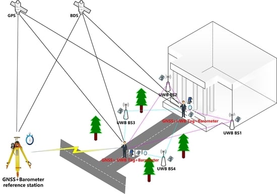
4.1. Experimental Data

The location of the experimental data collection site was on the top of Building No. 1 of the APM, CAS in Wuhan, on a slide trolley platform. As seen in Figure 4a, the reference station, which includes the Trimble Net R9 receiver, choke antenna, and BMP280 barometer, was situated on the fixed reference pier. The static and dynamic cart experiment sites are depicted in Figure 4b and Figure 5, respectively. The mobile station hardware equipment consists of a high-precision GNSS antenna that uses a power splitter to connect a single-frequency low-cost u-blox NEO-M8T receiver and a multi-frequency Septentrio MOSAIC-X5 mini receiver at the same time. In order to make sure that the antenna phase centers are positioned in the same vertical direction and to identify and correct for any vertical discrepancies during data pre-processing, the GNSS antenna, UWB Tag, and BMP280 barometer were mounted in a unified connection frame. To acquire a high-precision 3D coordinate sequence as a reference value, the multi-frequency Septentrio MOSAIC-X5 small receiver data processes used the post-process kinematic (PPK) mode of the commercial software Inertial Explorer 8.70.
At the experimental site, there are five UWB BS deployed concurrently, of which BS1 was the master BS and BS2, BS4, BS5, and BS7 were the slave BS. The 3D coordinates of each BS were predetermined by a total station and GNSS RTK device. The dynamic trolley’s sluggish motion speed allows all sensors to be time-synchronized with the aid of a laptop computer, and real-time observation data recording is possible. The experimental data were split into two periods. The static data acquisition duration for the first period time was from 4:50 to 6:28 (UTC), or a total of 1 h 38 min. The slide dynamic cart experiment was the second period, and it took around 37 min to complete. The acquisition time was between 8:40 and 9:17 (UTC).
The GNSS RTK/UWB/DBA fusion positioning model chooses a single-frequency u-blox NEO-M8T receiver GPS + BDS dual system for combination, and the mobile station receiver coordinate and ambiguity parameters are estimated using single epoch mode. The data processing strategy and parameter set are shown in Table 1. The ratio threshold value was set to 3 for the LAMBDA method of ambiguity resolution. By changing the number of UWB BS and the elevation mask angle (10 to 50 degrees), static and dynamic cart tests can simulate various complex settings.

4.2. Static Experimental Results and Analysis

The average PDOP value statistical results and PDOP value sequences for the GNSS RTK/UWB/DBA fusion positioning model at various elevation mask angles in the static environment are shown in Table 2 and Figure 6. As can be seen, the number of GNSS visible satellites dropped as the elevation mask angle rose, the satellite spatial geometry distribution deteriorated, and the PDOP values gradually grew. The average PDOP value of GNSS RTK was 3.87 when the elevation mask angle was at 40 degrees, and 9.57 when it was at 50 degrees. The PDOP value drastically decreased when DBA and UWB were added. More UWB BS was chosen to take part in positioning across all processing modes, and the more obviously the PDOP value decreased.
The ambiguity resolution success rate of the GNSS RTK/UWB/DBA fusion positioning model at various elevation mask angles in a static situation is shown in Table 3. The GNSS ambiguity resolution success rate was 89.90% when the elevation mask angle was 10 degrees; after adding UWB and DBA, the ambiguity resolution success rate did not increase further because there are currently enough observable satellites, so the fusion of other observation data did not significantly improve the ambiguity resolution success rate. The GNSS ambiguity resolution success rate rose to 96.27% when the elevation mask angle was 20 degrees, and it marginally rose when the UWB or DBA observations were included. This is because low elevation mask angle satellites with poor observation quality were removed.
As the elevation mask angle increased further (30 to 50 degrees), the number of GNSS visible satellites decreased significantly, and the ambiguity resolution success rate gradually decreased. In particular, when the elevation mask angle was 50 degrees, the GNSS ambiguity resolution success rate was only 19.15%; however, after fusing UWB and DBA, the effective observation value increased and the ambiguity resolution success rate significantly rose by 20% to 60%. Because it has the most observations, the GNSS RTK/UWB/DBA fusion model improved the ambiguity resolution success rate more than the GNSS RTK/UWB and GNSS RTK/DBA combination model. The improvement in the success rate of the ambiguity resolution was greater when more UWB BS were simultaneously engaged in positioning.
To analyze the positioning errors corresponding to the GNSS RTK/UWB/DBA fusion positioning models, the error interval distributions in the north (N)/east (E)/up (U) direction at the 30 and 50 degrees elevation mask angles are counted in Table 4 and Table 5, and the position errors in the N/E/U direction corresponding to the 30 and 50 degrees elevation mask angles are shown in Figure 7 and Figure 8.
Figure 7 shows that when the elevation mask angle is 30 degrees, there are enough GNSS visible satellites and a higher fraction of fixed solutions (blue point). In Table 4, the percentage of GNSS RTK positioning errors less than 1 cm in the N and E direction was greater than 83%, and larger than 90% for positioning errors less than 5 cm. The positioning accuracy of the float solution (red point) greatly increased after the addition of UWB and DBA, with the percentage of positioning errors smaller than 1 cm and 5 cm in the N/E/U directions improving by roughly 3% to 8%.
The percentage of the GNSS RTK fixed solutions rapidly declined as the elevation mask angle rose from 30 to 50 degrees, as shown in Table 3. The positioning error of the float solution could reach tens of meters, and the ambiguity resolution success rate was only 19.15% when the elevation mask angle was 50 degrees. Similarly, the fraction of positioning errors less than 5 cm in the N/E/U direction was about 20%. Following the addition of DBA, the accuracy of the float solution greatly increased, and the percentage of positioning errors less than 5 cm in the N and E directions increased by over 20% and it’s for 15% in the U direction. With more UWB added, the improvement ratio became more apparent; when there are five UWB BS, for example, the proportion of less than 5 cm in the N/E direction improved by 60%, and the U direction improved by about 50%.

4.3. Dynamic Cart Experimental Results and Analysis

In the dynamic cart experiment, the sequence of PDOP values and average PDOP values of the GNSS RTK/UWB/DBA fusion positioning model at various elevation mask angles are shown in Figure 9 and Table 6, respectively. As can be seen, as the elevation mask angle increased, fewer GNSS satellites became visible, the spatial geometry arrangement of the GNSS satellites deteriorated, and the PDOP values rose. The average PDOP values for GNSS RTK were 3.32 and 5.34 when the elevation mask angle was 40 degrees and 50 degrees, respectively, while they were 1.42 and 1.79 for the GNSS RTK/DBA model. In comparison to GNSS RTK, the average PDOP values in the GNSS RTK/UWB model were slightly lower. The GNSS RTK/UWB/DBA model had lower average PDOP values of 1.31 and 1.23 since it had more available observations than the other three models.
The statistics of the ambiguity resolution success rate for the GNSS RTK/UWB/DBA fusion positioning model for dynamic sliding carts are shown in Table 7 for various elevation mask angles. When the elevation mask angle was 10 degrees or 20 degrees, the ambiguity resolution success rate for GNSS RTK was 83.50% and 89.81%, respectively. The success rate for ambiguity resolution was somewhat increased by adding UWB and DBA. After removing satellites with low observation quality, the GNSS RTK ambiguity resolution success rate was 92.94% when the elevation mask angle was 30 degrees, and the GNSS RTK/UWB/DBA rose by around 5% in comparison to the GNSS RTK. The number of GNSS observation satellites was drastically reduced when the elevation mask angle was 50 degrees, and the success rate for ambiguity resolution dropped to 32.80%. The ambiguity resolution success rate increased by 17.1% when DBA was fused. When the number of UWB BS participating in positioning was raised from 2 to 5, the ambiguity resolution success rate of the GNSS RTK/UWB/DBA model was greatly boosted by around 35% to 56% compared with GNSS RTK.
Similarly to that in Section 4.2, to further analyze the positioning errors corresponding to the GNSS RTK/UWB/DBA fusion positioning models in the dynamic cart setting, the positioning error interval distributions in the N/E/U directions at the 30 and 50 degree elevation mask angles are counted in Table 8 and Table 9, and the dynamic cart trajectory in the plane direction and the position errors in the U direction are present in Figure 10 and Figure 11.
According to Table 8 and Figure 10, there were enough observable GNSS satellites, and the proportion of fixed solutions (blue point) was relatively greater with an elevation mask angle of 30 degrees. The positioning error of the GNSS RTK/UWB/DBA fusion positioning model, which was smaller than 5 cm in the N/E/U direction, can be improved by roughly 5% in comparison to the GNSS RTK model. Additionally, the positioning error improvement was more apparent as UWB BS were implemented, and the dynamic slider cart trajectory became smoother and the error of the float solution (red point) in the N/E/U direction also decreased.
It is evident from Table 9 and Figure 11a that in a dynamic cart environment with an elevation mask angle of 50 degrees, the ambiguity resolution success rate for GNSS RTK was only 32.80%. The GNSS RTK float solution positioning error reached the meter level, and the positioning error below 5 cm was less than 38% in the N/E/U direction. The ambiguity resolution success rate of the GNSS RTK/DBA model increased to 49.90%. The accuracy of the float solution greatly improved for thee GNSS RTK/DBA model, notably in the U direction, and a positioning error less than 5 cm in the N/E/U direction increased by more than 15%. The positioning error smaller than 5 cm in the N/E direction improved 35% to 60% after adding UWB with 3 and 5 BS, and it improved 23% to 55% in the U direction. The GNSS RTK/UWB/DBA fusion positioning model had the most robust positioning performance compare with the above three models. The 3D positioning error decrease was more pronounced the more UWB BS were utilized in positioning. This confirmed that the GNSS RTK/UWB/DBA fusion positioning has enough advantages compared with GNSS RTK in a complex situation.

4.4. Discussion

Due to issues such as signal occlusion and strong multipath effects, GNSS RTK struggles to produce accurate positioning results in local challenging and adverse situations such as building walls, under trees, and deep in open pits. The proposed GNSS RTK/UWB/DBA fusion positioning model can effectively improve the GNSS RTK ambiguity resolution success rate and positioning accuracy in the above harsh applications. The Earth ellipsoid constraint equation constructed by the DBA altitude is equivalent to adding a virtual satellite located at the center of the Earth. The combination of both UWB TDOA observations and DBA altitude can effectively improve the spatial geometry structure of the observation and reduce the PDOP value. The results of the static and dynamic cart experiments show that, in comparison to GNSS RTK positioning, the combined GNSS RTK/UWB/DBA positioning model greatly enhanced the ambiguity resolution success rate and 3D positioning accuracy. A comparison with the results of Chiu et al. [14] and Jiang [19] that used the GPS RTK/UWB combined positioning model in hostile environment and V2I navigation and UWB assisted GNSS RTK in this paper was also in good agreement with their results. Furthermore, the DBA technology added in this paper seems to be a very effective means to further improve the positioning accuracy of the GNSS RTK/UWB combination without increasing too much in cost. There also exist large research INS assisted GNSS RTK in a complex environment [47,48] that provides rich attitude information and a greater coverage range. However, compared with the GNSS RTK/UWB/DBA fusion positioning, the corresponding data processing of the GNSS RTK/INS combination is relatively difficult. The subsequent research will focus on the relevant algorithm model and performance evaluation after adding an INS sensor based on the GNSS RTK/UWB/DBA fusion positioning model.
According to Table 3 and Table 7, it is also important to note that the ambiguity resolution success rate increased more quickly when the UWB BS were chosen from 2 to 4 in the combined positioning. However, the improved effect was no longer noticeable when there were five BSs. This serves as a reminder that in local complicated situations, deploying fewer UWB BS can reduce costs while essentially satisfying the positioning requirements. In addition, despite the fact that the data processing in this study was based on the single epoch mode, the use of the filtering model for data processing is still worthy of further discussion.

5. Conclusions

In this study, the research of a GNSS RTK/UWB/DBA fusion positioning model and its performance evaluation was presented. To address the poor performance of GNSS RTK positioning in local complicated circumstances, we first suggested a GNSS RTK/UWB/DBA fusion positioning mathematical model. Next, its positioning performance was thoroughly assessed by static and dynamic cart experiments. The experimental results demonstrated that in the complicated environment produced by a 50 degree elevation mask angle, the number of GNSS satellites available was significantly reduced and the ambiguity resolution success rate was quite poor. When compared to GNSS RTK, the spatial geometric configuration was greatly improved and the PDOP value was decreased by the GNSS RTK/UWB/DBA fusion positioning model. Additionally, the positioning errors of less than 1 cm and 5 cm in the N/E/U direction were improved by 20% to 50%, and the success rate for the GNSS RTK ambiguity resolution increased from 20% to 60%. Combining the experimental results from the static and dynamic carts showed that the GNSS RTK/UWB/DBA fusion positioning model significantly improved the availability and reliability of GNSS RTK positioning in challenging local situations. The GNSS RTK/UWB/DBA fusion positioning model will be used in a follow-up study to locate pedestrians seamlessly indoors and outdoors and to control tiny unmanned aerial vehicles in formation. Other extra sensors such as the MEMS IMU will also be tested for integration.

Author Contributions

Conceptualization, S.W.; Methodology, S.W. and G.L.; Software, S.W., M.G., G.X., W.Z. and D.L.; Validation, M.G., W.Z. and D.L.; Formal analysis, M.G.; Investigation, S.W. and M.G.; Resources, G.L.; Data curation, S.W.; Writing—original draft preparation, S.W.; Writing—review and editing, X.D., G.L., M.G., W.Z., D.L. and G.X.; Visualization, S.W. and M.G.; Supervision, X.D. and G.L.; Project administration, X.D. and G.L.; Funding acquisition, S.W., X.D. and G.L. All authors have read and agreed to the published version of the manuscript.

Funding

This work was jointly supported by the Basic Research Program of Shanxi Province (Grant No. 202303021212284), the Open Foundation of the State Key Laboratory of Geodesy and Earth’s Dynamics (Grant No. SKLGED2022-3-4, SKLGED2022-3-3), and the Open Foundation of the State Key Laboratory of Satellite Navigation System and Equipment Technology (Grant No. CEPNT2022B07).

Acknowledgments

The authors would like to thank Shilong Cao and Chengfeng Zhang for their help in setting up the multi-sensor platform used in the dynamic cart experiments.

Conflicts of Interest

The authors declare no conflict of interest.

References

  1. Han, H.; Wang, J.; Wang, J.; Tan, X. Performance Analysis on Carrier Phase-Based Tightly-Coupled GPS/BDS/INS Integration in GNSS Degraded and Denied Environments. Sensors 2015, 15, 8685–8711. [Google Scholar] [CrossRef] [Green Version]
  2. Cristodaro, C.; Dovis, F.; Falco, G.; Pini, M. GNSS Receiver Performance in Urban Environment: Challenges and Test Approaches for Automotive Applications. In Proceedings of the International Conference of Electrical & Electronic Technologies for Automotive, Turin, Italy, 15–16 June 2017. [Google Scholar]
  3. Wang, C.; Xu, A.; Sui, X.; Hao, Y.; Shi, Z.; Chen, Z. A Seamless Navigation System and Applications for Autonomous Vehicles Using a Tightly Coupled GNSS/UWB/INS/Map Integration Scheme. Remote Sens. 2022, 14, 27. [Google Scholar] [CrossRef]
  4. Zirari, S.; Canalda, P.; Spies, F. WiFi GPS based combined positioning algorithm. In Proceedings of the 2010 IEEE International Conference on Wireless Communications, Networking and Information Security, Beijing, China, 25–27 June 2010; pp. 684–688. [Google Scholar]
  5. Wang, J.; Tsujii, T.; Rizos, C.; Dai, L.; Moore, M.J.G.R.A. GPS and pseudo-satellites integration for precise positioning. Geomat. Res. Australas. 2001, 74, 103–117. [Google Scholar]
  6. Tobie, A.-M.; Garcia-Pena, A.; Thevenon, P.; Vezinet, J.; Aubault, M. Hybrid navigation filters performances between GPS, Galileo and 5G TOA measurements in multipath environment. In Proceedings of the Proceedings of the 33rd International Technical Meeting of the Satellite Division of The Institute of Navigation (ION GNSS+ 2020), Online, 22–25 September 2020; pp. 2107–2140. [Google Scholar]
  7. Sahinoglu, Z.; Gezici, S.; Guvenc, I. Ultra-Wideband Positioning Systems (Theoretical Limits, Ranging Algorithms, and Protocols); Cambridge University Press: Cambridge, UK, 2008. [Google Scholar] [CrossRef] [Green Version]
  8. Bastida-Castillo, A.; Gómez-Carmona, C.D.; De La Cruz Sánchez, E.; Pino-Ortega, J. Comparing accuracy between global positioning systems and ultra-wideband-based position tracking systems used for tactical analyses in soccer. Eur. J. Sport Sci. 2019, 19, 1157–1165. [Google Scholar] [CrossRef]
  9. Alarifi, A.; Al-Salman, A.; Alsaleh, M.; Alnafessah, A.; Al-Hadhrami, S.; Al-Ammar, M.A.; Al-Khalifa, H.S. Ultra wideband indoor positioning technologies: Analysis and recent advances. Sensors 2016, 16, 707. [Google Scholar] [CrossRef] [PubMed] [Green Version]
  10. Yu, K.; Wen, K.; Li, Y.; Zhang, S.; Zhang, K. A Novel NLOS Mitigation Algorithm for UWB Localization in Harsh Indoor Environments. IEEE Trans. Veh. Technol. 2018, 68, 686–699. [Google Scholar] [CrossRef]
  11. Opshaug, G.R.; Enge, P. Integrated GPS and UWB Navigation System: (Motivates the Necessity of Non-Interference). In Proceedings of the IEEE Conference on Ultra Wideband Systems & Technologies, Baltimore, MD, USA, 21–23 May 2002. [Google Scholar]
  12. Tan, K.M.; Law, C.L. GPS and UWB Integration for indoor positioning. In Proceedings of the International Conference on Information, Singapore, 10–13 December 2007. [Google Scholar]
  13. Gonzalez, J.; Blanco, J.L.; Galindo, C.; Ortiz-De-Galisteo, A.; Fernandez-Madrigal, J.A.; Moreno, F.A.; Martinez, J.L. Combination of UWB and GPS for indoor-outdoor vehicle localization. In Proceedings of the 2007 IEEE International Symposium on Intelligent Signal Processing, Alcala de Henares, Spain, 3–5 October 2007; pp. 885–890. [Google Scholar] [CrossRef]
  14. Chiu, D.S.; Macgougan, G.; O’Keefe, K. UWB Assisted GPS RTK in Hostile Environments. In Proceedings of the ION GNSS 2008, The Satellite Division of the Institute of Navigation 20th International Technical Meeting, Savannah, GA, USA, 16–19 September 2008. [Google Scholar]
  15. Chiu, S.T. Ultra Wideband Augmented GPS; University of Calgary: Calgary, AB, Canada, 2008. [Google Scholar]
  16. MacGougan, G.D. Real-Time Kinematic Surveying Using Tightly-Coupled GPS and Ultra-Wideband Ranging; University of Calgary: Calgary, AB, Canada, 2009. [Google Scholar]
  17. MacGougan, G.D.; O’Keefe, K. Real Time UWB Error Estimation in a Tightly Coupled GPS/UWB Positioning System. In Proceedings of the Institute of Navigation 2009 International Technical Meeting, Anaheim, CA, USA, 26–28 January 2009. [Google Scholar]
  18. MacGougan, G.D.; O’Keefe, K.; Klukas, R. Accuracy and reliability of tightly coupled GPS/ultra-wideband positioning for surveying in urban environments. GPS Solut. 2010, 14, 351–364. [Google Scholar] [CrossRef]
  19. Jiang, Y. Integration of UWB Ranging and GPS for Improved Relative Vehicle Positioning and Ambiguity Resolution; University of Calgary: Calgary, AB, Canada, 2012. [Google Scholar]
  20. O’Keefe, K.; Jiang, Y.; Petovello, M. An Investigation of tightly-coupled UWB/low-cost GPS for vehicle-to-infrastructure relative positioning. In Proceedings of the Radar Conference, Cincinnati, OH, USA, 19–23 May 2014. [Google Scholar]
  21. Liu, F. Research on High Precision Seamless Positioning Model and Method Based on Multi-Sensor Fusion; China University of Mining and Technology: Xuzhou, China, 2020. [Google Scholar]
  22. Wang, N. The Key Modals and System of GNSS/UWB Network Positioning; Beijing University of Civil Engineering and Architecture: Beijing, China, 2020. [Google Scholar]
  23. Abolfathi, E.A.; O’Keefe, K. Integrating Vision Derived Bearing Measurements with Differential GPS and UWB Ranges for Vehicle-to-vehicle Relative Navigation. In Proceedings of the 26th International Technical Meeting of The Satellite Division of the Institute of Navigation (ION GNSS 2013), Nashville, TN, USA, 16–20 September 2013. [Google Scholar]
  24. Li, Z.; Zheng, N.; Wang, J.; Gao, J. Performance Comparison among Different Precise Satellite Ephemeris and Clock Products for PPP/INS/UWB Tightly Coupled Positioning. J. Navig. 2017, 71, 585–606. [Google Scholar] [CrossRef]
  25. Zhang, K.; Shen, C.; Zhou, Q.; Wang, H.; Gao, Q.; Chen, Y. A combined GPS UWB and MARG locationing algorithm for indoor and outdoor mixed scenario. Clust. Comput. 2018, 22, 5965–5974. [Google Scholar] [CrossRef]
  26. Wang, N.; Li, R.; Han, Z.; Qiu, W.; Wang, Z. Research on relative navigation algorithm of small UAV based on inertial/GNSS/UWB. Electron. Meas. Technol. 2019, 42, 94–100. [Google Scholar]
  27. Guo, R.; Su, R.R.; Liu, L.; Hu, G.M.; Chang, Z.Q. COMPASS RDSS Positioning Accuracy Analysis. In Proceedings of the 5th China Satellite Navigation Conference (CSNC), Nanjing, China, 21–23 May 2014; pp. 219–228. [Google Scholar]
  28. Abdalati, W.; Zwally, H.J.; Bindschadler, R.; Csatho, B.; Farrell, S.L.; Fricker, H.A.; Harding, D.; Kwok, R.; Lefsky, M.; Markus, T. The ICESat-2 laser altimetry mission. Proc. IEEE 2010, 98, 735–751. [Google Scholar] [CrossRef]
  29. Jao, C.-S.; Wang, Y.; Lin, Y.-W.; Shkel, A.M. A hybrid barometric/ultrasonic altimeter for aiding ZUPT-based inertial pedestrian navigation systems. In Proceedings of the 33rd International Technical Meeting of the Satellite Division of The Institute of Navigation (ION GNSS+ 2020), Online, 22–25 September 2020; pp. 2500–2517. [Google Scholar]
  30. Hu, Z.Q.; Zhang, L.R.; Ji, Y.F. Applications of differential barometric altimeter in ground cellular communication positioning network. IET Sci. Meas. Technol. 2020, 14, 322–331. [Google Scholar] [CrossRef]
  31. Wang, S.; Dong, X.; Liu, G.; Gao, M.; Zhao, W.; Lv, D.; Cao, S. Low-Cost Single-Frequency DGNSS/DBA Combined Positioning Research and Performance Evaluation. Remote Sens. 2022, 14, 586. [Google Scholar] [CrossRef]
  32. Guoxiang, A.I.; Sheng, P.X.; Jinlin, D.U.; Zheng, Y.G.; Cai, X.D.; Haitao, W.U.; Yonghui, H.U.; Hua, Y.A. Barometric altimetry system as virtual constellation applied in CAPS. Sci. China Ser. G–Phys. Mech. Astron. 2009, 38, 1702–1710. [Google Scholar]
  33. Shi, H.; Pei, J. The solutions of navigation observation equations for CAPS. Sci. China Ser. G–Phys. Mech. Astron. 2009, 52, 434–444. [Google Scholar] [CrossRef]
  34. Ji, Y.F.; Sun, X.Y. Analysis on the positioning precision of CAPS. Sci. China Ser. G–Phys. Mech. Astron. 2009, 52, 328–332. [Google Scholar] [CrossRef]
  35. Sabatini, A.M.; Genovese, V. A Sensor Fusion Method for Tracking Vertical Velocity and Height Based on Inertial and Barometric Altimeter Measurements. Sensors 2014, 14, 13324–13347. [Google Scholar] [CrossRef]
  36. Wang, H.; Wen, Y.; Zhao, D. Differential barometric-based positioning technique for indoor elevation measurement in IoT medical applications. Technol. Health Care Off. J. Eur. Soc. Eng. 2017, 25, S295–S304. [Google Scholar] [CrossRef] [Green Version]
  37. Masse, F.; Bourke, A.K.; Chardonnens, J.; Paraschiv-Ionescu, A.; Aminian, K. Suitability of commercial barometric pressure sensors to distinguish sitting and standing activities for wearable monitoring. Med. Eng. Phys. 2014, 36, 739–744. [Google Scholar] [CrossRef]
  38. Seok, H.W.; Ansari, K.; Panachai, C.; Jamjareegulgarn, P. Individual performance of multi-GNSS signals in the determination of STEC over Thailand with the applicability of Klobuchar model. Adv. Space Res. 2022, 69, 1301–1318. [Google Scholar] [CrossRef]
  39. Xu, G.; Xu, Y. GPS Theory, Algorithms and Applications, 3rd ed.; Science Press: Beijing, China, 2017. [Google Scholar]
  40. Bolanakis, D.E.; Laopoulos, T.; Kotsis, K.T. A Prototype Wireless Sensor Network System for a Comparative Evaluation of Differential and Absolute Barometric Altimetry. IEEE Aerosp. Electron. Syst. Mag. 2015, 30, 20–28. [Google Scholar] [CrossRef]
  41. Hu, Z. Study on Key Technologies in Integration System of Navigation Based on Multi-Sensor Information such as Differential Barometric Altimetry; University of Chinese Academy of Sciences: Beijing, China, 2014. [Google Scholar]
  42. Shi, H.-L.; Sun, X.; Li, Z. Principle of Forwarding Satellite Navigation; Science Press: Beijing, China, 2009. [Google Scholar]
  43. King, B.; Bock, Y. Documentation for the GAMIT GPS Analysis Software; Massachusetts Institute of Technology: Cambridge, MA, USA, 1999. [Google Scholar]
  44. Li, Z.; Hunag, J. GPS Surveying and Data Processing; Wuhan University Press: Wuhan, China, 2013. [Google Scholar]
  45. Teunissen, P.J.G. The least-squares ambiguity decorrelation adjustment: A method for fast GPS integer ambiguity estimation. J. Geod. 1995, 70, 65–82. [Google Scholar] [CrossRef]
  46. Chang, X.W.; Yang, X.; Zhou, T. MLAMBDA: A modified LAMBDA method for integer least-squares estimation. J. Geod. 2005, 79, 552–565. [Google Scholar] [CrossRef] [Green Version]
  47. Li, W.; Li, W.; Cui, X.; Zhao, S.; Lu, M. A Tightly Coupled RTK/INS Algorithm with Ambiguity Resolution in the Position Domain for Ground Vehicles in Harsh Urban Environments. Sensors 2018, 18, 2160. [Google Scholar] [CrossRef] [PubMed] [Green Version]
  48. Gao, M.; Liu, G.; Wang, S.; Xiao, G.; Zhao, W.; Lv, D. Research on Tightly Coupled Multi-Antenna GNSS/MEMS Single-Frequency Single-Epoch Attitude Determination in Urban Environment. Remote Sens. 2021, 13, 2710. [Google Scholar] [CrossRef]
Figure 1. UWB TDOA location principle in 2D space.
Remotesensing 14 05928 g001
Figure 2. Approximate reference ellipsoidal meridian profile where the ground user is located.
Remotesensing 14 05928 g002
Figure 3. Flowchart of GNSS RTK/UWB/DBA tight combination data processing.
Remotesensing 14 05928 g003
Figure 4. The GNSS RTK/UWB/DBA fusion static positioning experiment site: (a) reference station; (b) static experiment mobile station.
Remotesensing 14 05928 g004
Figure 5. GNSS RTK/UWB/DBA fusion dynamic cart positioning experiment site (UWB BSs are in the red round box, and the GNSS antenna, UWB Tag, and BMP280 barometer combined device are in the red rectangular box).
Remotesensing 14 05928 g005
Figure 6. The PDOP values for the GNSS RTK/UWB/DBA fusion positioning model for various elevation mask angles in a static environment. The elevation mask angles were as follows: (a) 10 degrees; (b) 20 degrees; (c) 30 degrees; (d) 40 degrees; (e) 50 degrees.
Remotesensing 14 05928 g006
Figure 7. GNSS RTK/UWB/DBA fusion positioning model error in the N/E/U directions at a 30 degree elevation mask angle: (a) GNSS RTK; (b) GNSS RTK/DBA; (c) GNSS RTK/UWB−3BS; (d) GNSS RTK/UWB−5BS; (e) GNSS RTK/UWB−3BS/DBA; (f) GNSS RTK/UWB−5BS/DBA.
Remotesensing 14 05928 g007
Figure 8. GNSS RTK/UWB/DBA fusion positioning model error in the N/E/U directions at a 50 degree elevation mask angle: (a) GNSS RTK; (b) GNSS RTK/DBA; (c) GNSS RTK/UWB−3BS; (d) GNSS RTK/UWB−5BS; (e) GNSS RTK/UWB−3BS/DBA; (f) GNSS RTK/UWB−5BS/DBA.
Remotesensing 14 05928 g008
Figure 9. Sequence of the PDOP values of the GNSS RTK/UWB/DBA fusion positioning model at various elevation mask angles in the dynamic cart environment. The elevation mask angles were as follows: (a) 10 degrees; (b) 20 degrees; (c) 30 degrees; (d) 40 degrees; (e) 50 degrees.
Remotesensing 14 05928 g009
Figure 10. GNSS RTK/UWB/DBA fusion positioning model dynamic cart trajectory in the plane direction and positioning error in the U direction at a 30 degree elevation mask angle: (a) GNSS RTK; (b) GNSS RTK/DBA; (c) GNSS RTK/UWB−3BS; (d) GNSS RTK/UWB−5BS; (e) GNSS RTK/UWB−3BS/DBA; (f) GNSS RTK/UWB−5BS/DBA.
Remotesensing 14 05928 g010aRemotesensing 14 05928 g010b
Figure 11. GNSS RTK/UWB/DBA fusion positioning model dynamic cart trajectory in the plane direction and positioning error in the U direction error at a 50 degree elevation mask angle: (a) GNSS RTK; (b) GNSS RTK/DBA; (c) GNSS RTK/UWB−3BS; (d) GNSS RTK/UWB−5BS; (e) GNSS RTK/UWB−3BS/DBA; (f) GNSS RTK/UWB−5BS/DBA.
Remotesensing 14 05928 g011aRemotesensing 14 05928 g011b
Table 1. GNSS RTK/UWB/DBA fusion positioning data processing strategy and parameter set.
Parameter TypeProcessing Strategy
GNSS receiveru-blox NEO-M8T
UWB system and rangeTracTech, from 50 to 100 m
BMP280 barometer resolution0.01 mbar (0.1 m)
Position parametersSingle epoch mode
Atmospheric delaysIgnored in short baseline length
Ambiguity parametersSingle epoch mode and LAMBDA method resolution
Ratio threshold value3.0
DBA altitudeSimplified DBA formula
UWB BS numberFrom 2 to 5
Table 2. Average PDOP values of the GNSS RTK/UWB/DBA fusion positioning model at various elevation mask angles in a static scenario.
Combination ModeUWB BSElevation Mask Angles (Degrees)
1020304050
GNSS RTK-1.281.422.563.879.57
GNSS RTK/DBA-0.981.041.321.471.94
GNSS RTK/UWB21.231.382.333.659.12
31.211.342.303.658.43
41.201.332.262.944.78
51.181.312.173.124.72
GNSS RTK/UWB/DBA20.940.991.191.311.47
30.900.951.111.191.27
40.900.941.101.171.23
50.890.941.091.161.22
Table 3. The ambiguity resolution success rate of the GNSS RTK/UWB/DBA fusion positioning model at various elevation mask angles in a static environment.
Combination ModeUWB BSElevation Mask Angles (Degrees)
1020304050
GNSS RTK-89.90%96.27%90.02%82.76%19.15%
GNSS RTK/DBA-90.73%97.19%93.68%91.62%43.06%
GNSS RTK/UWB288.58%97.21%93.45%85.43%39.91%
388.87%98.36%97.89%94.00%57.50%
488.61%98.47%98.91%97.07%65.86%
587.40%98.28%98.53%96.63%76.04%
GNSS RTK/UWB/DBA289.22%97.68%96.25%94.17%64.79%
389.33%98.48%98.96%97.07%80.55%
489.08%98.56%99.06%97.29%81.40%
587.39%98.36%98.80%96.83%79.08%
Table 4. Statistics of thee GNSS RTK/UWB/DBA fusion positioning model error distribution intervals in N/E/U directions at a 30 degree elevation mask angle.
Combination ModeUWB BS<1 cm<5 cm
NEUNEU
GNSS RTK-83.41%90.14%49.97%90.46%90.68%90.19%
GNSS RTK/DBA-84.17%93.78%49.84%93.97%94.29%94.09%
GNSS RTK/UWB386.35%97.89%53.81%98.01%97.96%97.90%
586.96%98.58%54.10%98.55%98.82%98.52%
GNSS RTK/UWB/DBA386.99%98.96%53.85%98.96%99.03%98.93%
586.99%98.84%54.19%98.82%98.98%98.88%
Table 5. Statistics of the GNSS RTK/UWB/DBA fusion positioning model error distribution intervals in the N/E/U directions at a 50 degree elevation mask angle.
Combination ModeUWB BS<1 cm<5 cm
NEUNEU
GNSS RTK-18.27%18.78%7.50%18.71%21.59%18.54%
GNSS RTK/DBA-41.72%43.10%16.39%43.25%45.81%43.17%
GNSS RTK/UWB351.19%53.89%20.71%56.49%56.78%49.01%
568.22%75.22%25.50%76.17%80.37%64.65%
GNSS RTK/UWB/DBA373.77%79.55%29.14%80.57%83.94%70.08%
570.52%77.81%26.77%79.17%83.00%67.08%
Table 6. Average PDOP values of the GNSS RTK/UWB/DBA fusion positioning model at various elevation mask angles in the dynamic cart environment.
Combination ModeUWB BSElevation Mask Angles (Degrees)
1020304050
GNSS RTK-1.301.712.243.325.34
GNSS RTK/DBA-1.011.121.251.421.79
GNSS RTK/UWB21.301.702.223.303.28
31.261.662.193.293.02
41.171.552.033.172.56
51.171.532.002.982.33
GNSS RTK/UWB/DBA21.011.111.241.411.60
30.981.091.221.401.53
40.941.041.171.351.36
50.931.031.151.311.23
Table 7. The ambiguity resolution success rate of the GNSS RTK/UWB/DBA fusion positioning model at various elevation mask angles in the dynamic cart situation.
Combination ModeUWB BSElevation Mask Angles (Degrees)
1020304050
GNSS RTK-83.50%89.81%92.94%88.17%32.80%
GNSS RTK/DBA-83.85%90.26%94.48%91.15%49.90%
GNSS RTK/UWB284.29%91.75%95.58%89.66%57.06%
384.89%92.25%94.78%90.71%71.27%
485.14%92.64%97.61%97.17%84.94%
585.04%92.79%98.16%98.16%88.77%
GNSS RTK/UWB/DBA284.84%91.70%96.27%95.43%67.15%
385.14%92.35%97.12%96.22%79.82%
485.09%92.69%97.96%97.61%86.93%
585.04%92.79%98.21%98.16%89.51%
Table 8. Statistics of the GNSS RTK/UWB/DBA fusion positioning model error distribution intervals at a 30 degree elevation mask angle in the dynamic cart scenario.
Combination ModeUWB BS<1 cm<5 cm
NEUNEU
GNSS RTK-92.84%89.91%70.87%93.04%93.89%93.04%
GNSS RTK/DBA-94.33%91.25%71.57%94.58%95.28%94.88%
GNSS RTK/UWB394.09%90.06%70.68%95.33%95.58%94.83%
597.37%91.55%66.60%98.71%98.81%98.21%
GNSS RTK/UWB/DBA396.42%91.85%72.42%97.71%97.86%97.27%
597.42%91.40%66.00%98.71%98.86%98.41%
Table 9. Statistics of the GNSS RTK/UWB/DBA fusion positioning model error distribution intervals at a 50 degrees elevation mask angle in the dynamic cart scenario.
Combination ModeUWB BS<1 cm<5 cm
NEUNEU
GNSS RTK-32.95%33.35%9.69%34.94%37.18%33.85%
GNSS RTK/DBA-50.05%50.30%14.21%51.74%53.18%53.23%
GNSS RTK/UWB370.68%70.97%14.36%73.01%74.35%70.18%
588.72%88.42%19.53%93.84%90.90%88.02%
GNSS RTK/UWB/DBA380.77%79.87%17.99%85.69%82.41%80.02%
589.02%89.02%19.63%93.99%91.40%88.97%
Publisher’s Note: MDPI stays neutral with regard to jurisdictional claims in published maps and institutional affiliations.

