Article

Shadow Compensation from UAV Images Based on Texture-Preserving Local Color Transfer

1
School of Information and Communication Engineering, North University of China, Taiyuan 030051, China
2
Department of Computer Science, University of Reading, Reading RG6 6AY, UK
*
Author to whom correspondence should be addressed.
Remote Sens. 2022, 14(19), 4969; https://doi.org/10.3390/rs14194969
Submission received: 3 September 2022 / Revised: 27 September 2022 / Accepted: 30 September 2022 / Published: 6 October 2022
(This article belongs to the Section Remote Sensing Image Processing)

Abstract

:
The lack of color information and texture information in the shadow region seriously affect the recognition and interpretation of remote sensing image information. The commonly used methods focus on the restoration of texture information, but it is often easy to overcompensate, resulting in color distortion of the shadow region. However, some methods only ensure accurate correction of color information, and tend to cause texture blurring. In order to not lose the texture information and to accurately compensate the color information in the shadow region of the image, we propose a shadow compensation method from UAV images based on texture-preserving local color transfer in this paper. Firstly, homogeneous regions are extracted from UAV images and homogeneous subregion segmentation is performed on the basis of homogeneous regions using the mean shift method. Secondly, in combination with the shadow mask, each shadow subregion is matched with the corresponding non-shadow subregion based on its texture features and spatial distance. Then, the matched non-shadow subregion is used as the reference region, and the color transfer based on preserving texture is performed on the shadow subregion. Finally, pixel-by-pixel width shadow compensation is applied to the penumbra region. The results of the qualitative and quantitative analysis validate the accuracy and effectiveness of the proposed methodology to compensate for the color and texture details of the shadow regions.

Graphical Abstract

1. Introduction

With the widespread application of unmanned aerial vehicle (UAV) low-altitude remote sensing technology, the effective utilization of its images has widely concerned researchers [1,2]. Images acquired by drones are easily affected by lighting, terrain and weather, resulting in poor quality. One of the most common degradation phenomena is the appearance of shadows. Due to the influence of violently undulating terrain, trees and buildings of different heights, clouds in the sky, etc., and in an environment where the light is too strong or insufficient, the drone image is prone to shadows, which makes the areas covered by shadows appear blurred and affecting important features, with poor contrast and other degradation phenomena [3,4,5]. However, the degraded images greatly affect the image matching accuracy, DOM product quality and image interpretation accuracy involved in subsequent image processing, resulting in the images not being effectively utilized [6,7]. In order to restore the lost information in the shadow regions, shadow compensation is an essential preprocessing step in the interpretation of UAV remote sensing images. The existing UAV image shadow compensation algorithms focus on the restoration of texture information, but this often tends to overcompensate, resulting in color distortion of the shadow area, while some methods easily cause texture blurring without losing color information, which seriously affects the recognition and interpretation of image information. Therefore, how to not lose texture information, but also accurately compensate for the color information of the shadow area of the image, is of great significance to the application of UAV images in object detection [8,9,10], precision agriculture [11,12,13], urban region analysis [14,15,16,17] and other fields.
Highly accurate shadow detection results are a significant prerequisite for shadow compensation. Effective shadow detection not only helps to accurately locate the shadow region, but also helps to reasonably restore the real information about the features in the shadow region. The shadow region is the part of the image where the information is obscured, and the information about the non-shadow region is the main source of the information restore of the shadow region. How to use the information of the non-shadow region to compensate the information about the shadow region is the key to the shadow compensation [18,19]. In the past decades, researchers have proposed various shadow compensation methods [20,21,22,23,24]. Finlayson et al. [25] used the Poisson equation to correct the gradient information on the shadow boundary, and reconstructed the shadow-free image based on the corrected information. However, due to the completely zero gradients, the texture information in the boundary is lost. Li et al. [26] proposed a variation model method to compensate shadows by eliminating the shadow intensity component in the image, but the results are highly dependent on the estimation of the shadow intensity, and eliminating the shadow intensity completely often leads to loss of color information. Silva et al. [27] established a linear mapping model between shadow and non-shadow regions based on light transfer. This model requires that the shadow samples and non-shadow samples used to estimate the lighting compensation parameters have similar texture materials, which means that this method only works well in the shadow region of a single texture. In short, the above methods can directly remove shadows as a whole but are not good at restoring details to the image.
Compared with the direct overall shadow removal method, the local shadow compensation method that restores the spectral information of shadow pixels or regions based on adjacent non-shadow information is favored by researchers. Guo et al. [28] proposed an illumination model that compensates for the illumination of the shadow regions by estimating the ratio between ambient and direct light and relighting each shadow pixel. Zhang et al. [29] proposed an illumination restoration operator that exploits the texture similarity of shadow and non-shadow regions to compensate for shadow region information. These methods can generate high-quality shadow-free results for simple images. However, for UAV images with complex shadows, the results are often inconsistent with non-shadow areas due to the low brightness of the shadows and the difficulty of accurately matching non-shadows. Liu et al. [30] established a color and texture equalization compensation model by using the information of homogeneous shadow regions and non-shadow regions. The color information was effectively compensated, but its adaptive ability was not enough to change the model parameters to obtain the most appropriate compensation results, so it may still be ineffective in restoring image details. Based on the above analysis, local region compensation can lead to better shadow compensation results. However, for UAV remote sensing images with a wide variety of ground objects and more complex spatial details than close-range images, it is urgent to develop a new method that does not lose texture information but also accurately compensates for the color information in the shadow region of the image.
In recent years, color transfer based on statistical information, as a new visual effect processing technology, has attracted the attention of related researchers [31,32,33,34,35]. Reinhard et al. [36] proposed an algorithm for global color migration in Lab color space [37], which laid the foundation for the subsequent development. The algorithm calculates the mean and standard deviation of the color channel of the two images in Lab color space, and makes the statistic of the target image consistent with that of the reference image through a set of linear transformations, so as to achieve the effect that the target image has the tone of the reference image visually. Based on this idea, Murali et al. [38] proposed a shadow removal method for single texture images based on Lab color space, and Gilberto et al. [39] proposed a UAV image shadow compensation method based on color transfer and color adjustment. They make the shadow region as close as possible to the non-shadow region in terms of overall color and color fluctuation amplitude, so as to achieve the purpose of shadow compensation. However, the algorithm only takes the color information of the non-shadow region as the criterion, and completely ignores the details such as the edge and texture of the shadow region. The pursuit of the color information and the non-shadow region gives exactly the same result and is likely to lead to the loss of the details of the shadow region, which is obviously not what we want to happen.
Based on the above inspiration, by combining the advantages of local region compensation and color transfer, we propose a method of UAV image shadow compensation based on texture-preserving local color transfer. The main contributions of the proposed approach are as follows: (1) Combining texture features and spatial distance features, a reference region search and matching model is established to match the corresponding non-shadow subregions for the shadow subregions. (2) Considering both color and texture, a novel local color transfer scheme preserving image texture is proposed for shadow compensation. (3) A pixel-by-pixel width shadow compensation method is proposed for penumbra compensation.

2. Materials and Methods

The flowchart of the proposed methodology is shown in Figure 1. Firstly, homogeneous regions are extracted from UAV images and homogeneous subregion segmentation is performed on the basis of homogeneous regions using mean shift method. Second, the shadow mask combines with the search for non-shadow subregions corresponding to the matching shadow subregions based on texture features and spatial distance features, which are noted as reference regions. Then, a novel method based on texture-preserving local color transfer scheme is proposed from both aspects, color and texture, and the reference region information is used to compensate the shadow subregion. Finally, considering that there are usually severe boundary effects in the shadow removal results, pixel-by-pixel width shadow compensation is applied to the penumbra region.

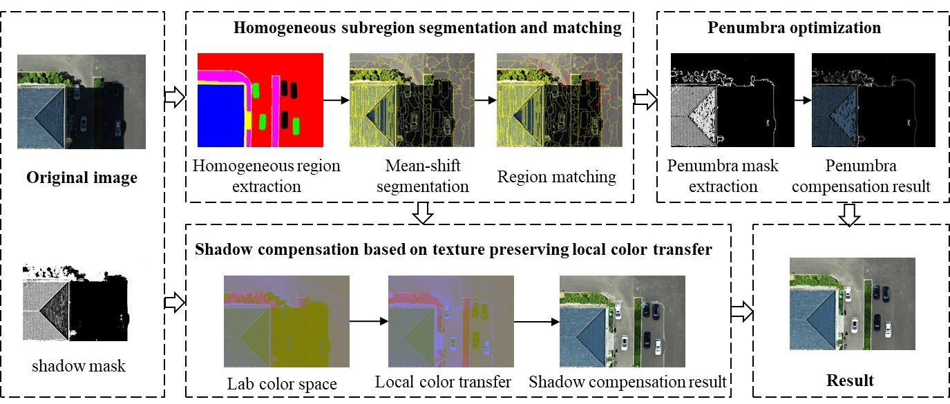
2.1. Homogeneous Subregion Segmentation with Mean Shift Method

UAV images are rich in content, and the shadow regions usually contain multiple ground object types. We considered the reflectance difference between different features in shadow compensation and used the homogeneous region extraction algorithm of reference [30] to extract homogeneous regions from UAV images. However, in a homogeneous region, two subregions with the same reflectance present similar colors only if the brightness is the same, otherwise the color and intensity of the two subregions may be different. As shown in Figure 2, there are still differences in light intensity and reflectance in different regions of the image in the same ground object material (asphalt road). It is difficult to obtain good results if unified parameters are used to compensate shadows.
In order to achieve better shadow compensation, the mean shift method is used for homogenous subregion segmentation. The mean shift method [40] is a non-parametric clustering technique; that is, without any prior knowledge, an image is segmented into an arbitrary number of significant or meaningful regions, in which image pixels with similar spectral and texture features are clustered together, and it has demonstrated excellent performance in image segmentation. After the comparative analysis, we set the radius of the segmentation space (sp) as 9, the radius of the segmentation color space (sr) as 15 and the minimum segmentation region (minRegion) as 100.

2.2. Subregion Search and Matching

For each subregion in the shadow region, it is necessary to find the corresponding subregion in the non-shadow region as the reference region for shadow compensation. The reference region search and matching algorithm consists of two steps. Firstly, the covariance matrix is used to extract the texture features of each subregion in the homogeneous shadow region and non-shadow region. Then the subregion matching process is performed. For each subregion in the shadow region, three best-matched subregions are found in the non-shadow region, and the matching combination of subregions is obtained.
Let S = S 1 , S 2 , , S m and U = U 1 , U 2 , , U n be the set of subregions inside the homogeneous shadow regions and the homogeneous non-shadow regions, respectively. m is the number of the subregions in S and n is the number of the subregions in U. According to [29], the texture features of each subregion of S and U are calculated. The feature vector of each pixel is a 6D vector (intensity, chromaticity, first derivatives of the intensity in x and y directions, second derivatives of the intensity in x and y directions). For the subregion R, C R is a 6 × 6 covariance matrix, and its feature vector f C R transformed into Euclidean space is expressed as
f C R = μ , 6 L 1 , , 6 L 6 , 6 L 1 , , 6 L 6 Τ
where, C R = L L Τ , and L i is the ith column data in the lower triangular matrix L . By comparing the feature vectors f C R , the N subregions with the most similar features are searched in U as candidate matching regions for the shadow subregions. In order to ensure the accuracy and efficiency of the matching process, we set N = 5 in the experiment.
In order to ensure local consistency, the spatial distance of two subregions is used as another criterion to judge regional similarity. The spatial distance between the shadow subregion S i and the non-shadow subregion U j is defined as
d s i , j = S x ¯ i U x ¯ j 2 + S y ¯ i U y ¯ j 2
where, S x ¯ i and S y ¯ i , respectively, represent the average value of x and y coordinates of all pixels in S i . Similarly, U x ¯ j and U y ¯ j represent the average of the x and y coordinates of all pixels in U j , respectively. Calculate the spatial distance between the shadow subregion and its candidate matching region. The M ( M N ) regions with the smallest spatial distance are selected as the best matching subregion of S i ; that is, the reference region for shadow compensation of the subregion S i , and the matching combination of this region is denoted as S i , r i , 1 , r i , 2 , , r i , M , we set M = 3 in the experiment.

2.3. Shadow Compensation

2.3.1. Color Transfer

Based on the statistical information of the color image, such as the mean and standard deviation, Reinhard’s color transfer algorithm corrects the color of the target image and makes it have the mean and standard deviation of the reference image through a set of linear transformations, so as to achieve the purpose of color similarity between the two images. Firstly, the image is transformed into Lab color space (Lab color space is a color opposition space with dimensions L representing brightness, a and b representing color opposition dimensions, which is based on CIE XYZ color space with non-linear compression. It not only basically eliminates the strong correlation between color components, but also effectively separates the grayscale information from the color information of the image, thus not affecting the natural effect of the original image), and then the target image is transferred approximately equidistant according to the Lab value of the reference image through statistical operation to realize the color transfer algorithm between color images. The main steps are as follows:
(1) The RGB space with close correlation of the data of each channel is transformed into Lab color space where the colors can be approximately orthogonally separated.
(2) Calculate the mean and standard deviation of each channel of the reference image and the target image respectively, as shown in Equation (3), and perform approximate isometric migration of the target image according to the statistical value of the reference image.
X = σ r X σ t X × X t μ t X + μ r X
where, σ t X and σ r X are, respectively, the standard deviation of the target image and the reference image in channel X; μ t X and μ r X are, respectively, the mean value of the target image and the reference image in channel X; and X is the value of target image X t after isometric migration in channel X, where X L , a , b .
(3) The image data in Lab color space is converted to RGB color space.

2.3.2. Texture-Preserving Color Transfer

The Reinhard’s algorithm only considers the color information of the image and completely ignores the details of the target image itself, so it is likely to blur the texture information of the image in the process of processing. Based on the above reasons, a local color transfer considering both color and detail is proposed for shadow compensation.
The gradient can be used as a quantitative measure of texture information. The larger the gradient is, the more violent the texture fluctuation is. The smaller the gradient, the more gently the texture fluctuates. Since gradient is the difference between adjacent pixels and has nothing to do with the value of a single pixel itself, consider the most special case, that is, if each pixel of the image has the same increment before and after the transformation, then the gradient matrix of the image remains unchanged before and after the transformation, and it can be considered that the details of the image are completely preserved. Make a difference on both sides of Equation (3)
Δ X * = σ r X σ t X × Δ X t
It can be seen from Equation (4) that the gradient information of the image under the action of Reinhard’s algorithm is only related to the factor σ r X σ t X . When σ r X = σ t X , the Reinhard’s algorithm can complete the corresponding color transfer while keeping the details of the target area completely unchanged, which is the most ideal situation. When σ r X > σ t X , the Reinhard’s algorithm will lead to the increase in the gradient of the target area. Although the increase in texture contrast can improve the clarity of the image, it may cause image distortion. When σ r X < σ t X , the Reinhard’s algorithm causes the image texture to be flat and the texture information of the target area is blurred. It is concluded that the same mean operation in Reinhard’s algorithm does not affect the details of the target region. The same standard deviation operation is the only reason to change the details of the target area. The specific change is related to the standard deviation of both the reference area and the target area. Therefore, both gradient and standard deviation should be taken into account, and the final scaling ratio should be chosen between 1 and σ r X σ t X . Here, we use linear interpolation to obtain the scaling weights and obtain the texture-preserving color transfer form as follows
X * = k 1 × σ r X σ t X + k 2 × X t μ t X + μ r X
where, k 1 , k 2 0 , 1 and k 1 + k 2 = 1 . We set k 1 = 0 . 8 , k 2 = 0 . 2 in the experiment.
The segmented shadow subregion is taken as the minimum processing unit, and the relationship between the intensity of the shadow region and the non-shadow region is constructed by using the color transfer technology to compensate the missing information of the shadow region. The Algorithm 1 of shadow compensation based on texture-preserving local color transfer is described as follows:
Algorithm1. Shadow compensation algorithm
Input: UAV RGB image I ; The number of homogeneous regions, n; k1, k2.
Output: The result of shadow compensation, U f r e e .
1. Image I is converted to Lab color space;
2. For any homogeneous region I j , j 1 , 2 , , n , represents all of its subregion matching combinations as S i j , r i , 1 j , r i , 2 j , r i , 3 j , i 1 , 2 , , m ;
3. for (j=1; j n; j++) do
4.  for (i=1; i m; i ++) do
5.   compute the average value ( S i , q j , μ ) and standard deviation ( S i , q j , σ ) of S i j in the q-band, ( q L , a , b );
6.   compute the average value ( r i , q , 1 j , μ , r i , q , 2 j , μ , r i , q , 3 j , μ ) and standard deviation ( r i , q , 1 j , σ , r i , q , 2 j , σ , r i , q , 3 j , σ ) of r i , 1 j , r i , 2 j , r i , 3 j in the q-band, ( q L , a , b );
7.    r i , q j , μ = r i , q , 1 j , μ + r i , q , 2 j , μ + r i , q , 3 j , μ 3 ;
8.    r i , q j , σ = r i , q , 1 j , σ + r i , q , 2 j , σ + r i , q , 3 j , σ 3 ;
9.    s i , q j = k 1 × r i , q j , σ S i , q j , σ + k 2 × S i , q j S i , q j , μ + r i , q j , μ ;// color transfer
10.  end for
11.   I j , q = i = 1 m S i , q j ; // the shadow compensation result of homogeneous region I j in the q-band
12. end for
13. I q = j = 1 n I j , q ; // the shadow compensation result of image I in the q-band
14. Image I is converted to RGB color space, U p f r e e , p R , G , B ;
15. U f r e e = p = R , G , B U p f r e e ; // RGB image composition
16. return U f r e e ;

2.4. Penumbra Optimization

After using the above shadow compensation method to compensate the whole shadow region, it is found that there is the shadow boundary effect on the compensation result. Since the shadow is usually composed of the umbra and penumbra, the umbra is the darkest part of the shadow, while the penumbra is the boundary transition area of the shadow, and the intensity gradually changes between the umbra and the illuminated area. If the dynamic change in penumbra intensity is not considered, the pixels at the shadow boundary will be oversaturated after compensation.
Through statistical analysis of the sample intensity at the shadow boundary, as shown in Figure 3, x is the normalized pixel position in the sampling area, x1 and x2 are the starting point and ending point of the penumbra region, respectively, then the penumbra width is d = x 2 x 1 (in our experiment, the d of ROI1 and ROI2 is 9, and the d of ROI3 and ROI4 is 3). Due to the weak shadow intensity in the penumbra region, the extracted shadow mask cannot cover all the penumbra pixels. As shown in Figure 4, although most of the penumbra region is detected, there are still a small number of penumbra pixels that cannot be detected by the shadow detection algorithm. After experimental statistics, we find that about 2/3 of the penumbra width pixels are covered by shadow mask, and 1/3 of the penumbra width pixels have very weak shadow characteristics and are not recognized.
Based on the above analysis, pixel-by-pixel width shadow compensation is carried out in the penumbra region in this paper, and the Algorithm 2 of penumbra compensation is described as follows:
Algorithm 2. Penumbra compensation algorithm
Input: UAV RGB image I ; Shadow mask Smask; Penumbra width d; k1, k2.
Output: The result of penumbra shadow compensation, P f r e e .
1. Image I is converted to Lab color space;
2. The Smask was morphologically dilated by 1/3d pixels in the non-shadow direction and morphologically eroded by 2/3d pixels in the umbra direction to obtain the penumbra mask, Pmask;
3. The Pmask morphologically dilated five pixel widths toward the non-shaded direction was used as a reference sample for color transfer;
4. For any homogeneous region I j , j 1 , 2 , , n , represents all of its subregion matching combinations as P j , R j ;
5. for (j=1; j n; j++) do
6.  for (i=1; i d; i ++) do
7.   compute the average value ( P i , q j , μ ) and standard deviation ( P i , q j , σ ) of P i j in the q-band, ( q L , a , b );
8.   compute the average value ( R i , q j , μ ) and standard deviation ( R i , q j , σ ) of R j in the q-band, ( q L , a , b );
9.   P i , q j = k 1 × R i , q j , σ P i , q j , σ + k 2 × P i , q j P i , q j , μ + R i , q j , μ ; // color transfer
10. end for
11. P j , q = i = 1 d P i , q j ; // the penumbra shadow compensation result of homogeneous region I j in the q-band
12. end for
13. P q = j = 1 n P j , q ; // the penumbra shadow compensation result of image I in the q-band
14. Image I is converted to RGB color space, P p f r e e , p R , G , B ;
15. P f r e e = p = R , G , B P p f r e e ; // RGB image composition
16. return P f r e e ;

3. Experiments

3.1. Experiment Data

The experimental data were obtained from aerial photography in Xinzhou City, Shanxi Province, Shanxi, China (112°43′E, 38°27′N), as shown in Figure 5. The DJI “PHANTOM 4 RTK” drone is equipped with a CMOS camera of 20 effective megapixels. The UAV flight altitude is 85 m, and its ground sampling distance is 2.51 cm. UAV images containing typical urban features such as buildings, vegetation, vehicles and asphalt roads were selected as experimental data, as shown in Figure 6a,b, and the resolution of the images was 1500 × 1100 pixels; UAV images of farmland crops showing irregular and fragmented shadows were also selected as experimental data, as shown in Figure 6c,d, with a resolution of 370 × 330 pixels. The shadow masks used were calculated by the method we developed in our previous work, as shown in Figure 7. By analyzing the color characteristics of UAV RGB remote sensing images, a new shadow detection index (SDI) is proposed to enhance the shadow [30]. The overall average accuracy of shadow detection results is up to 98.23%, which provides a good prerequisite for shadow compensation.

3.2. Experiment Design

In order to verify the superiority of the shadow compensation method proposed in this paper, the experimental results are compared with the current state-of-the-art shadow compensation algorithms for UAV images. For quantitative evaluation, color difference (CD) [30], shadow standard deviation index (SSDI) [18] and gradient similarity (GS) [30] were used to evaluate color, texture and boundary consistency, respectively, as shown in Table 1. The lower the CD and SSDI values, the closer the GS value is to 1, indicating that the compensated shadow region is more consistent with the non-shadow region.

3.3. Experimental Result

The shadow compensation results of UAV images in the four test areas are shown in Figure 8. In order to observe the details of feature information restoration under shadows, the experimental results (orange boxed regions in Figure 8) of each method are locally enlarged, as shown in Figure 9. In addition, to study the shadow compensation results and the penumbra compensation effect in detail, the homogeneous area around the shadow boundary is selected to perform the profile analysis in Figure 10, and the positions of the profile lines are marked with red lines in Figure 8. By calculating the CD, SSDI and GS, Table 2, Table 3 and Table 4 show the results of the quantitative analysis for all comparative methods in the four tested regions, respectively.

4. Discussion

4.1. Parameter Settings and Discussion

In order to take into account the color and texture detail information of shadow compensation, in Section 2.3.2 we introduce the key parameters k1 and k2 (k1 + k2 = 1) in the local color transfer to realize the color transfer that preserves the details. Due to the sensitivity of the parameter setting, the influence of local standard deviation ratio factor k1 on shadow compensation performance was analyzed by adjusting the value of the parameter k1.
Root Mean Square Error (RMSE) is selected as the error metric of shadow compensation accuracy, and its formula is shown in Equation (6). A lower RMSE means that the compensated shadow region is more similar to the real non-shadow region; that is, a smaller RMSE value provides better shadow compensation performance.
R M S E = 1 M × N i = 1 M j = 1 N I i , j r I i , j f 2
where I i , j r and I i , j f represent the pixels of the reference sample and the image after shadow compensation, respectively.
The four typical test regions in Section 3.1 were selected for analysis, and the relationship between RMSE values and k1 is shown in Figure 11. It can be seen that the RMSE curves show almost the same trend in the R, G and B bands of the four images. When k1 is 0.8 to 0.9, the RMSE value is the smallest and the shadow compensation effect is the best. In this paper, k1 = 0.8 is selected for experiments, which may be an optimal setting for almost all cases. Therefore, in the shadow compensation based on color transfer, the color information of an image shadow region can be accurately compensated without losing the texture information.

4.2. Analysis and Discussion of Experimental Results

The shadow compensation results and corresponding local enlargement regions of the UAV images of ROI1 and ROI2 are shown in the first two columns of Figure 8 and Figure 9, respectively. It can be observed that the illumination correction shadow compensation algorithm proposed by Silva et al. loses color restoration accuracy when shadows cover the asphalt road. The corrected asphalt area shows distinctly blue, and the shadow boundary is clearly visible due to over-illumination correction, as shown in Figure 9a. The color information and texture information of the shadow region after being processed by Gilberto’s method are inconsistent with the surrounding environment. The asphalt area shows a slight green color, and the texture information in the vegetation area is blurred, as shown in Figure 9b. The method proposed by Liu et al. can effectively restore the color information of the shadow region, and the shadow boundary effect is significantly weakened, but the accurate texture information is not presented in the asphalt area, as shown in Figure 9c. Figure 9d shows the method proposed (without penumbra compensation). It is obvious that the color difference is reduced after shadow compensation, and the texture information is also accurately preserved, but the shadow boundaries are still visible. The result after penumbra compensation is shown in Figure 9e. The details of the image are restored well without obvious shadow boundary. Therefore, the method proposed can not only well preserve the color and texture information in areas such as roads and vegetation, but also significantly improve the penumbra effect.
The shadow compensation results and corresponding local enlargement regions of farmland crop UAV images of ROI3 and ROI4 are shown in the last two columns of Figure 8 and Figure 9, respectively. When there are a large number of irregular, fragmented and darker shadows, the method of Silva et al. improves the brightness of the shadow regions. However, the shadow boundary is obvious and noisy, and the color information and texture information of the compensated shadow regions are also inconsistent with the non-shadow regions, as shown in Figure 9a. Gilberto’s method has blurred texture details and obvious shadow boundary artifacts, as shown in Figure 9b. Liu’s method has no obvious shadow boundary, but still has a small color difference, as shown in Figure 9c. Figure 9d shows that the color information and texture details in the shadow regions of the proposed method are visually consistent with the non-shadow regions. In addition, as shown in Figure 9e, the shadow boundary is well eliminated without obvious artifacts.
Figure 10 is the profile analysis diagram at the position of the red profile line in Figure 8. In the four test regions, compared with the non-shadow part, the pixel intensity values of the shadow part after compensation by Silva’s method (blue curve) and Gilberto’s method (green curve) show obvious fluctuations, especially in the penumbra. After compensation by Liu’s method (purple curve), the fluctuation amplitude of the pixel intensity value curve in the shaded part is slightly smaller. The pixel intensity value curves also show steep peaks at the penumbra if the method proposed in this paper is not processed by the shadow boundary (red curve). However, after penumbra compensation (black curve), the pixel intensity values in the shadow part always maintain the same trend as in the non-shadow part, with no significant differences. Based on the above analysis, the detailed area profile analysis results in Figure 10a–d show that the shadow compensation results of the proposed method are closer to the surrounding non-shadow regions than the other three methods. Therefore, the proposed method exhibits good performance in correcting the penumbra region.
In addition to the visual comparison of the shadow compensation results described above, we also evaluated them quantitatively. Table 2 shows the CD values for the compensation results for all testing methods. The average CD value of our method in the four sets of experiments is 1.109, which is 3.784, 2.839 and 0.778 lower than the average CD values of Silva’s, Gilberto’s and Liu’s methods, respectively, which shows a small perception of color difference. Table 3 shows the SSDI values for the compensation results. The average SSDI value of our method in four sets of experiments is 7.338, which is 12.525, 9.648 and 8.149 lower than the average SSDI values of Silva’s, Gilberto’s and Liu’s methods, respectively, which indicates that the texture detail information is well restored by our method. Table 4 shows the GS values for the compensation results. The average GS value of our method in four sets of experiments is 0.836, which is 0.328, 0.299 and 0.102 higher than the average GS values of Silva’s, Gilberto’s and Liu’s methods, respectively, which effectively reduces the boundary effect. The above quantitative analysis indicates that the shadow region compensated by our method is more consistent with the non-shadow region.
In summary, Silva et al. used the light information from the non-shadow regions to compensate to the shadow regions, and the brightness of the compensated shadowed regions was improved to some extent. However, there are still differences between the improved shadow regions and the real feature colors, for example, a noticeable bluish color in the asphalt and concrete regions, mainly due to the lack of color correction in the shadow regions. Gilberto et al. used a local color transfer method to remove shadows and used the HSV color space for color adjustment, which enhanced color consistency. However, the corrected shadows show a slight green color and there is overcompensation in the penumbra regions. Liu et al.’s color and texture equalization compensation method restored the shadow region information better, but due to the uneven light distribution and the image blocking effect, the method produced block artifacts, resulting in blurred texture in some regions. Relatively speaking, our method accurately restores the color and texture information of the shadow regions, and the shadow boundary is also effectively restored. However, through a large number of tests, it is found that our method inevitably has false positives. The main reasons for this phenomenon are: (1) the subregion matching algorithm has poor matching accuracy for a fine patch; (2) the setting of penumbra width relies on manual statistical analysis. In the subsequent study, the threshold value at matching should be improved to enhance the matching accuracy of shadow subregions and non-shadow subregions, and a method of adaptively determining the penumbra width to enhance the accuracy of penumbra extraction should be sought to compensate for this deficiency.

5. Conclusions

In order not to lose the texture information, but also to accurately compensate the color information of the shadow region of the image, we combine the advantages of local optimization and color transfer, and propose a shadow compensation method from UAV images based on texture-preserving local color transfer in this paper. Experiments on the method in urban and farmland scenes with a wide variety of objects and shadow shapes have yielded good results. The main conclusions are as follows:
(1) From the visual comparison of the experimental results, the proposed method accurately restores the color and texture information of the shadow region, and effectively eliminates the shadow boundary effect. The compensated shadow region has high consistency with the surrounding real environment. In the quantitative analysis, the average CD value of the proposed method is 1.109, the average SSDI value is 8.388 and the average GS value is 0.836, all of which are better than the other three test methods, verifying the superiority of the proposed method.
(2) Comprehensively considering the color and texture information of the image, the texture-preserving local color transfer is realized. In particular, it has significant advantages in the restoration of color and texture information in the shadow region of UAV images. It effectively improves the image quality after shadow compensation.
In the future, we will continue to optimize the shadow compensation algorithm to try to solve the problem of restoring detail information in very dark shadows. We will consider using a texture transfer method to restore dark area shadows with very weak detail information, and combine our current research to improve the performance of shadow compensation.

Author Contributions

Conceptualization, F.Y., X.L. and H.W.; methodology, X.L. and M.G.; software, X.L.; validation, X.L. and F.Y.; formal analysis, X.L.; investigation, X.L.; resources, F.Y. and X.L.; data curation, F.Y., X.L. and M.G.; writing—original draft preparation, X.L. and F.Y.; writing—review and editing, H.W.; supervision, F.Y. and H.W.; project administration, F.Y.; funding acquisition, F.Y. and H.W. All authors have read and agreed to the published version of the manuscript.

Funding

This research was funded by the National Natural Science Foundation of China (NSFC), grant number 61972363, Central Government Leading Local Science and Technology Development Fund Project, grant number YDZJSX2021C008, the Postgraduate Education Innovation Project of Shanxi Province, grant number 2021Y612.

Institutional Review Board Statement

Not applicable.

Informed Consent Statement

Informed consent was obtained from all subjects involved in the study.

Data Availability Statement

If you are interested in data used in our research work, you can contact s2005004@st.nuc.edu.cn for the original dataset.

Conflicts of Interest

The authors declare no conflict of interest.

References

  1. Mo, N.; Zhu, R.; Yan, L.; Zhao, Z. Deshadowing of Urban Airborne Imagery Based on Object-Oriented Automatic Shadow Detection and Regional Matching Compensation. IEEE J. Sel. Top. Appl. Earth Obs. Remote Sens. 2018, 11, 585–605. [Google Scholar] [CrossRef]
  2. Sieberth, T.; Wackrow, R.; Chandler, J.H. Automatic detection of blurred images in UAV image sets. ISPRS J. Photogramm. Remote Sens. 2016, 122, 1–16. [Google Scholar] [CrossRef] [Green Version]
  3. Wang, C.; Xu, H.; Zhou, Z.; Deng, L.; Yang, M. Shadow Detection and Removal for Illumination Consistency on the Road. IEEE Trans. Intell. Veh. 2020, 5, 534–544. [Google Scholar] [CrossRef]
  4. Han, H.; Han, C.; Huang, L.; Lan, T.; Xue, X. Irradiance Restoration Based Shadow Compensation Approach for High Resolution Multispectral Satellite Remote Sensing Images. Sensors 2020, 20, 6053. [Google Scholar] [CrossRef] [PubMed]
  5. Chen, Y.; He, W.; Yokoya, N.; Huang, T. Blind cloud and cloud shadow removal of multitemporal images based on total variation regularized low-rank sparsity decomposition. ISPRS J. Photogramm. Remote Sens. 2019, 157, 93–107. [Google Scholar] [CrossRef]
  6. Yang, J.; He, Y.; Caspersen, J. Fully constrained linear spectral unmixing based global shadow compensation for high resolution satellite imagery of urban areas. Int. J. Appl. Earth Obs. Geoinf. 2015, 38, 88–98. [Google Scholar] [CrossRef]
  7. Ankush, A.; Kumar, S.; Singh, D. An Adaptive Technique to Detect and Remove Shadow from Drone Data. J. Indian Soc. Remote. 2021, 49, 491–498. [Google Scholar]
  8. Wu, B.; Liang, A.; Zhang, H.; Zhu, T.; Zou, Z.; Yang, D.; Tang, W.; Li, J.; Su, J. Application of conventional UAV-based highthroughput object detection to the early diagnosis of pine wilt disease by deep learning. For. Ecol. Manag. 2021, 486, 118986. [Google Scholar] [CrossRef]
  9. Zhang, H.; Sun, M.; Li, Q.; Liu, L.; Liu, M.; Ji, Y. An empirical study of multi-scale object detection in high resolution UAV images. Neurocomputing 2021, 421, 173–182. [Google Scholar] [CrossRef]
  10. Tian, G.; Liu, J.; Yang, W. A dual neural network for object detection in UAV images. Neurocomputing 2021, 443, 292–301. [Google Scholar] [CrossRef]
  11. Aboutalebi, M.; Torres-Rua, A.F.; McKee, M.; Kustas, W.; Nieto, H.; Coopmans, C. Behavior of vegetation/soil indices in shaded and sunlit pixels and evaluation of different shadow compensation methods using UAV high-resolution imagery over vineyards. In Autonomous Air and Ground Sensing Systems for Agricultural Optimization and Phenotyping III; International Society for Optics and Photonics: Orlando, FL, USA, 2018; Volume 10664, p. 1066407. [Google Scholar]
  12. Gao, M.; Yang, F.; Wei, H.; Liu, X. Individual Maize Location and Height Estimation in Field from UAV-Borne LiDAR and RGB Images. Remote Sens. 2022, 14, 2292. [Google Scholar] [CrossRef]
  13. Hamuda, E.; Mc Ginley, B.; Glavin, M.; Jones, E. Automatic crop detection under field conditions using the HSV colour space and morphological operations. Comput. Electron. Agric. 2017, 133, 97–107. [Google Scholar] [CrossRef]
  14. Lyu, Y.; Vosselman, G.; Xia, G.S.; Yilmaz, A.; Yang, M.Y. UAVid: A semantic segmentation dataset for UAV imagery. ISPRS J. Photogramm. Remote Sens. 2020, 165, 108–119. [Google Scholar] [CrossRef]
  15. Yang, F.; Wei, H.; Feng, P. A hierarchical Dempster-Shafer evidence combination framework for urban area land cover classification. Measurement 2020, 151, 105916. [Google Scholar] [CrossRef]
  16. Shao, H.; Song, P.; Mu, B.; Tian, G.; Chen, Q.; He, R.; Kim, G. Assessing city-scale green roof development potential using Unmanned Aerial Vehicle (UAV) imagery. Urban For. Urban Green. 2021, 57, 126954. [Google Scholar] [CrossRef]
  17. Yang, F.; Ji, L.; Wang, X. Possibility Theory and Application; Science Press: Beijing, China, 2019; pp. 186–194. [Google Scholar]
  18. Luo, S.; Shen, H.; Li, H.; Chen, Y. Shadow removal based on separated illumination correction for urban aerial remote sensing images. Signal Process. 2019, 165, 197–208. [Google Scholar] [CrossRef]
  19. Zhou, T.; Fu, H.; Sun, C. Shadow Detection and Compensation from Remote Sensing Images under Complex Urban Conditions. Remote Sens. 2021, 13, 699. [Google Scholar] [CrossRef]
  20. Zhang, Y.; Chen, G.; Vukomanovic, J.; Singh, K.; Liu, Y.; Holden, S.; Meentemeyer, R.K. Recurrent Shadow Attention Model (RSAM) for shadow removal in high-resolution urban land-cover mapping. Remote Sens. Environ. 2020, 247, 111945. [Google Scholar] [CrossRef]
  21. Wen, Z.; Wu, S.; Chen, J.; Lyu, M.; Jiang, Y. Radiance transfer process based shadow correction method for urban regions in high spatial resolution image. J. Remote Sens. 2016, 20, 138–148. [Google Scholar]
  22. Xiao, C.; Xiao, D.; Zhang, L.; Chen, L. Efficient Shadow Removal Using Subregion Matching Illumination Transfer. Comput. Graph. Forum 2013, 32, 421–430. [Google Scholar] [CrossRef] [Green Version]
  23. Amin, B.; Riaz, M.M.; Ghafoor, A. Automatic shadow detection and removal using image matting. Signal Process. 2019, 170, 107415. [Google Scholar] [CrossRef]
  24. Qu, L.; Tian, J.; He, S.; Tang, Y.; Lau, R.W.H. DeshadowNet: A Multi-context embedding deep network for shadow removal. In Proceedings of the IEEE Conference on Computer Vision and Pattern Recognition (CVPR), Honolulu, HI, USA, 21–26 July 2017; pp. 2308–2316. [Google Scholar]
  25. Finlayson, G.D.; Drew, M.S.; Lu, C. Entropy minimization for shadow removal. Int. J. Comput. Vision. 2009, 85, 35–57. [Google Scholar] [CrossRef]
  26. Li, H.; Zhang, L.; Shen, H. An adaptive nonlocal regularized shadow removal method for aerial remote sensing images. IEEE Trans. Geosci. Remote Sens. 2014, 52, 106–120. [Google Scholar] [CrossRef]
  27. Silva, G.F.; Carneiro, G.B.; Doth, R.; Amaral, L.A.; De Azevedo, D.F.G. Near real-time shadow detection and removal in aerial motion imagery application. ISPRS J. Photogramm. Remote Sens. Lett. 2017, 140, 104–121. [Google Scholar] [CrossRef]
  28. Guo, R.; Dai, Q.; Hoiem, D. Single-image shadow detection and removal using paired regions. In Proceedings of the IEEE Conference Computer Vision and Pattern Recognition (CVPR), Colorado Springs, CO, USA, 20–25 June 2011; pp. 2033–2040. [Google Scholar]
  29. Zhang, L.; Zhang, Q.; Xiao, C. Shadow remover: Image shadow removal based on illumination recovering optimization. IEEE Trans. Image Process. 2015, 24, 4623–4636. [Google Scholar] [CrossRef]
  30. Liu, X.; Yang, F.; Wei, H.; Gao, M. Shadow Removal from UAV Images Based on Color and Texture Equalization Compensation of Local Homogeneous Regions. Remote Sens. 2022, 14, 2616. [Google Scholar] [CrossRef]
  31. Murali, S.; Govindan, V.K.; Kalady, S. Quaternion-based image shadow removal. Vis. Comput. 2022, 38, 1527–1538. [Google Scholar] [CrossRef]
  32. Song, Z.; Liu, S. Sufficient Image Appearance Transfer Combining Color and Texture. IEEE Trans. Multimed. 2017, 19, 702–711. [Google Scholar] [CrossRef]
  33. Pang, G.; Zhu, M.; Zhou, P. Color transfer and image enhancement by using sorting pixels comparison. Optik 2015, 126, 3510–3515. [Google Scholar] [CrossRef]
  34. Wu, T.; Tang, C.; Brown, M.S.; Shum, H. Natural shadow matting. ACM Trans. Graph. 2007, 26, 8–es. [Google Scholar] [CrossRef]
  35. Yu, X.; Ren, J.; Chen, Q.; Sui, X. A false color image fusion method based on multi-resolution color transfer in normalization YCBCR space. Optik 2014, 125, 6010–6016. [Google Scholar] [CrossRef]
  36. Reinhard, E.; Ashikhmin, M.; Gooch, B.; Shirley, P. Color transfer between images. IEEE Comput. Graph. 2001, 21, 34–41. [Google Scholar] [CrossRef]
  37. Ruderman, D.L.; Cronin, T.W.; Chiao, C. Statistics of cone responses to natural images: Implications for visual coding. J. Opt. Soc. Am. A 1998, 15, 2036–2045. [Google Scholar] [CrossRef] [Green Version]
  38. Murali, S.; Govindan, V.K. Shadow detection and removal from a single image: Using LAB color space. Cybern. Inf. Technol. 2013, 13, 95–103. [Google Scholar] [CrossRef] [Green Version]
  39. Gilberto, A.; Francisco, J.S.; Marco, A.G.; Roque, A.O.; Luis, A.M. A Novel Shadow Removal Method Based upon Color Transfer and Color Tuning in UAV Imaging. Appl. Sci. 2021, 11, 11494. [Google Scholar]
  40. Comaniciu, D.; Meer, P. Mean shift: A robust approach toward feature space analysis. IEEE Trans. Pattern Anal. Mach. Intell. 2002, 24, 603–619. [Google Scholar] [CrossRef]
Figure 1. Flowchart of the proposed methods.
Remotesensing 14 04969 g001
Figure 2. Example of different light intensity and reflectance of the same material.
Remotesensing 14 04969 g002
Figure 3. Shadow model.
Remotesensing 14 04969 g003
Figure 4. Penumbra schematic.
Remotesensing 14 04969 g004
Figure 5. Geographical position of study area.
Remotesensing 14 04969 g005
Figure 6. UAV RGB images: (a) ROI1; (b) ROI2; (c) ROI3; (d) ROI4.
Remotesensing 14 04969 g006
Figure 7. Shadow masks: (a) ROI1; (b) ROI2; (c) ROI3; (d) ROI4.
Remotesensing 14 04969 g007
Figure 8. The compensation results of different methods applied to the four study regions: (a) Silva’s method; (b) Gilberto’s method; (c) Liu’s method; (d) the proposed method (without penumbra compensation); (e) the proposed method (with penumbra compensation).
Remotesensing 14 04969 g008
Figure 9. Local enlargement of the compensation results of different methods applied to the four study regions: (a) Silva’s method; (b) Gilberto’s method; (c) Liu’s method; (d) the proposed method (without penumbra compensation); (e) the proposed method (with penumbra compensation).
Remotesensing 14 04969 g009aRemotesensing 14 04969 g009b
Figure 10. Profile analysis of the four detailed regions: (a) ROI1; (b) ROI2; (c) ROI3; (d) ROI4.
Remotesensing 14 04969 g010
Figure 11. Sensitivity analysis of parameter k1 in the four test regions: (a) ROI1; (b) ROI2; (c) ROI3; (d) ROI4.
Remotesensing 14 04969 g011aRemotesensing 14 04969 g011b
Table 1. Metrics of quantitative evaluation.
MetricsFormulas
CD             Δ E l a b = Δ L 2 + Δ a 2 + Δ b 2 1 / 2
L, a and b are, respectively, the three channels of LAB color space.
SSDI             σ s n s = 1 B b = 1 B 1 N i = 1 N F b , i s F b n s ¯ 2
b is the current band of the image and B is the total number of image bands. i is the current pixel in the shadow regions and N is the total number of pixels in the shadow regions. F s is the compensated shadow sample set, and F n s ¯ is the mean of the corresponding non-shadow sample set.
GS             g x , y = 2 g x g y + C g x 2 + g y 2 + C , g x , y 0 , 1
g x and g y represent the central gradient values of image blocks x and y, respectively, and C is a smaller positive constant, in order to prevent the instability of the algorithm caused by too small a denominator.
Table 2. Quantitative evaluation results of color difference (CD).
RegionsSilva [27]Gilberto [39]Liu [30]Proposed Work
ROI14.8633.9121.7921.048
ROI24.3404.0531.9431.290
ROI35.2073.7861.9981.117
ROI45.1624.0391.8150.981
AVG4.8933.9481.8871.109
Table 3. Quantitative evaluation results of shadow standard deviation index (SSDI).
RegionsSilva [27]Gilberto [39]Liu [30]Proposed Work
ROI123.32619.14516.5097.583
ROI219.87217.48217.1827.801
ROI318.31016.21214.2536.949
ROI417.94316.10514.0047.020
AVG19.86316.98615.4877.338
Table 4. Quantitative evaluation results of gradient similarity (GS).
RegionsSilva [27]Gilberto [39]Liu [30]Proposed Work
ROI10.4910.5340.7690.832
ROI20.5030.5510.6730.791
ROI30.5100.5090.7400.856
ROI40.5310.5540.7520.863
AVG0.5080.5370.7340.836
Publisher’s Note: MDPI stays neutral with regard to jurisdictional claims in published maps and institutional affiliations.

