Technical Note

Performance Evaluation of Multi-Epoch Double-Differenced Pseudorange Observation Method Using GNSS Ground Stations

1
Department of Astronautics and Aeronautics, Chubu University, 1200 Matsumoto-cho, Kasugai 487-8501, Japan
2
Department of Electrical & Computer Engineering, College of Technology, University of Houston, 306 Technology 2 Bldg., Calhoun Road, Houston, TX 77004, USA
*
Author to whom correspondence should be addressed.
Remote Sens. 2022, 14(19), 4856; https://doi.org/10.3390/rs14194856
Submission received: 15 August 2022 / Revised: 26 September 2022 / Accepted: 26 September 2022 / Published: 29 September 2022
(This article belongs to the Special Issue Autonomous Space Navigation)

Abstract

:
Multi-epoch double-differenced pseudorange observation (MDPO) is a dual-satellite lunar navigation algorithm specially designed for a precursor mission, using a minimum number of lunar orbiting small satellites to realize a GNSS-like radio navigation system for the Moon. In this study, we evaluated the performance of the MDPO algorithm by using real pseudorange measurements obtained from a pair of GNSS ground stations, one of which represented a lander, and the other a rover on the Moon. It was natural that the resulting positioning accuracy varied largely by satellite geometry, but the estimated error distributions of the double-differenced pseudorange observations were consistent and agreed with the predicted value. The results showed that the MDPO algorithm worked properly with the real GNSS observables and was capable of providing the expected navigation performance for future lunar exploration missions.

Graphical Abstract

1. Introduction

As part of human exploration of the Moon, a wide variety of commercial and international missions have been undertaken to send robotic landers and rovers to the surface of the Moon [1]. To support the growing number of ongoing and scheduled robotic activities and improve their autonomous operation capabilities, future lunar missions will require reliable infrastructure to provide navigation and communication services to the explorers on the Moon. For this purpose, robotic rovers will be used for resource mapping and scientific observation missions on the lunar surface. Earlier studies have reported that a positioning accuracy of less than 100 m is required to support these goals [2].
There are several ongoing feasibility studies on dedicated lunar orbiting satellite constellations like the Global Navigation Satellite System (GNSS) around the Earth [3,4,
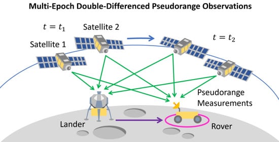
5]. While they can provide robust and precise navigation services to the entire Moon’s surface and its proximity, the transportation cost to inject many satellites into multiple lunar orbits is not affordable at the early stage of lunar exploration programs. To reduce the initial deployment cost of the lunar navigation satellite constellations, the authors proposed a new dual-satellite navigation method called multi-epoch double-differenced pseudorange observation (MDPO), which requires range observations from only two navigation satellites in a single orbit plane [6]. Furthermore, it is still quite challenging for lunar orbiting satellites to achieve reasonable orbit and clock determination as well as prediction accuracies, especially for a small satellite with its limited size, weight, and power. The MDPO algorithm efficiently eliminates these error sources by taking a double-differenced measurement between a lander and a rover.
Although there are several operational limitations in availability and real-time property, MDPO can handle the typical pseudorange observables provided by the satellites in the future full constellation. Since there is no special treatment required for the first two navigation satellites, it is quite suitable for a temporal precursor mission by the completion of the full constellation. More details about the MDPO algorithm and comprehensive numerical analysis results can be found in the early work [7].
In this study, to evaluate the performance of the MDPO algorithm with real pseudorange observations, we applied it to GNSS pseudorange measurements obtained from a pair of GNSS ground stations emulating a lander and a rover on the lunar surface. Since the resulting positioning accuracy varied largely by satellite geometry, the consistency of the navigation performance was evaluated by the estimated measurement errors of the double-differenced pseudorange observations.

2. MDPO Positioning Method

In this section, we provide a brief description of the MDPO algorithm and its requirements. First, it is a relative positioning method and requires a pair of receivers, one of which will be on the lander as a base station and the other on the rover. The position of the lander must be determined before rover deployment by other means. For example, the Lunar Reconnaissance Orbiter Camera (LROC) successfully identified the location of the Chinese Chang’e 5 lunar lander with an accuracy of 20 m [8].
At a time of t i , each receiver provides pseudorange measurements expressed by the following equation:
ρ R S ( t i ) = r R S ( t i ) + c ( d τ R ( t i ) d T S ( t i S ) ) + ω R S ( t i ) ,
where the subscript R and the superscript S represent the receiver and one of the tracking satellites, respectively, c is the speed of light, d τ R ( t i ) is the receiver clock bias, d T S ( t i S ) is the satellite clock bias including the range offset due to the satellite position error, and ω R S ( t i ) represents the pseudorange noise. The true range between the receiver and the satellite can be defined as:
r R S ( t i ) = x S ( t i S ) x R ( t i ) ,  
where x R ( t i ) is the receiver position vector at the time of t i , and x S ( t i S ) is the satellite position vector at the corresponding signal transmission time of t i S .
Now, we assume two navigation satellites, S = 1 ,   2 , which are commonly visible from both the lander ( R = 1 ) and the rover ( R = 2 ). Then, we have the following four pseudorange observations at each epoch t i :
ρ 1 1 ( t i ) = r 1 1 ( t i ) + c ( d τ 1 ( t i ) d T 1 ( t i 1 ) ) + ω 1 1 ( t i )   ,  
ρ 1 2 ( t i ) = r 1 2 ( t i ) + c ( d τ 1 ( t i ) d T 2 ( t i 2 ) ) + ω 1 2 ( t i ) ,  
ρ 2 1 ( t i ) = r 2 1 ( t i ) + c ( d τ 2 ( t i ) d T 1 ( t i 1 ) ) + ω 2 1 ( t i ) ,
ρ 2 2 ( t i ) = r 2 2 ( t i ) + c ( d τ 2 ( t i ) d T 2 ( t i 2 ) ) + ω 2 2 ( t i ) .
For typical GNSS pseudorange observations, the magnitude of d T S ( t i S ) is reasonably small, and it is treated as a known parameter provided in the broadcast navigation message. For the lunar orbiting satellites, however, it is challenging to obtain reasonable orbit and clock determination and prediction accuracies especially for a small satellite. For example, the expected orbit determination accuracy of EQUULEUS, a 6U-size CubeSat to be launched to an Earth-Moon L2 quasi-Halo orbit, was reported about a kilometer by using range and range rate observations obtained on two ground stations [9]. It is three orders of magnitude larger than a typical GPS ephemeris error, which is usually in the order of a meter.
Fortunately, these errors can be virtually eliminated by combining the simultaneous observations from the receivers. Since the two receivers are both observing the same satellite at the same time, the difference in the satellite clock bias errors between the receivers is obviously zero. Moreover, if the baseline between the two receivers is shorter than the distance to a satellite by orders of magnitude, the range bias due to the satellite position error is also the same between the receivers. In addition, since each receiver is observing two satellites simultaneously, the receiver clock error d τ R ( t i ) can also be eliminated by differencing the pseudorange measurement of one satellite from that of the other. Finally, when the two types of differences are combined, the result is known as a double-differenced measurement. From Equations (3)–(6), it could be written as:
Δ ρ ( t i ) = ( ρ 1 1 ( t i ) ρ 2 1 ( t i ) ) ( ρ 1 2 ( t i ) ρ 2 2 ( t i ) ) = Δ r ( t i ) Δ ω ( t i ) ,
where Δ denotes the double-difference operation. The resulting double-differenced pseudorange is composed of only the double-differenced true range and pseudorange noise. Although the noise is increased by the double-difference operation, both the receiver clock and the satellite-related bias errors are efficiently eliminated.
In order to eliminate the satellite and the receiver clock bias errors from the double-differenced measurements, time synchronization between the two receivers is essential. In the common GPS positioning, it can be achieved in the position calculation process by estimating the receiver clock bias at the same time. However, the receiver clock bias is removed in the double-differenced observation and cannot be estimated. Since the maximum range rate of the pseudorange observation obtained from a low lunar orbiting satellite is about 1.3 km/s, the resulting range error is no larger than 1.3 m if the time synchronization error is maintained under 1 ms. This could be achieved by the frame synchronization of the navigation signals transmitted from the lunar orbiting satellites or the communication link signal between the rover and the lander.
Since the baseline is much shorter than the distance to a satellite, the following relationship is obtained:
Δ r ( t i ) = ( r 1 1 ( t i ) r 2 1 ( t i ) ) ( r 1 2 ( t i ) r 2 2 ( t i ) ) = ( l 1 1 ( t i ) l 1 2 ( t i ) ) · b ( t i ) ,
where b ( t i ) is the relative position vector between the two receivers, defined as the following:
b ( t i ) = x 2 ( t i ) x 1 ( t i ) ,
and l 1 S ( t i ) is the unit direction vector from the base station receiver, which is the lander in this case, to the satellite. It is called the line-of-sight (LOS) vector and could be written as:
l 1 S ( t i ) = x S ( t i S ) x 1 ( t i ) x S ( t i S ) x 1 ( t i ) .  
Since the lander location x 1 ( t i ) = x 1 is stationary and is assumed to be well known, the rover position x 2 ( t i ) in Equation (9) can be written as the following:
x 2 ( t i ) = b ( t i ) + x 1 ,
where the relative position b ( t i ) is the only unknown vector composed of three unknown parameters.
Let us now consider the relative position estimation based on Equation (8). In order to estimate b ( t i ) , we need at least three linearly independent observations. With the two satellites in view, however, only one double-differenced pseudorange measurement is available at each epoch. To overcome this issue, we assume the rover position b ( t i ) = b is also stationary during multiple observation periods t i   ( i = 1 ,   2 , ,   N ) , where N must be greater than or equal to the number of unknown parameters in b . Then the double-differenced pseudorange measurements from multiple observation periods can be written in vector-matrix notation as below:
[ Δ ρ ( t 1 ) Δ ρ ( t 2 ) Δ ρ ( t N ) ] = [ ( l 1 1 ( t 1 ) l 1 2 ( t 1 ) ) T ( l 1 1 ( t 2 ) l 1 2 ( t 2 ) ) T ( l 1 1 ( t N ) l 1 2 ( t N ) ) T ] b [ Δ ω ( t 1 ) Δ ω ( t 2 ) Δ ω ( t N ) ] .
This is the typical over-determination set of linear equations, and the relative position vector b can be estimated by the least-squares method. Equation (12) can be rewritten in general vector and matrix form as:
y = G b + ϵ ,  
where y and ϵ are the observation and the residual vectors, respectively, and G is called the geometric matrix. Then the least-squares solution b ^ that minimizes the sum of squared residuals ϵ T ϵ can be obtained from:
b ^ = ( G T G ) 1 G T y .
In order to solve the relative position vector b in Equation (12), the rover must be stationary for at least three observation periods. Further reduction in the stationary periods can be achieved if the topocentric height of the rover is known. Equation (12) can be easily transformed into the local ENU (East-North-Up) coordinate frame by writing the LOS vector l 1 S ( t i ) as below:
l 1 S ( t i ) = [ cos δ 1 S ( t i ) sin γ 1 S ( t i ) cos δ 1 S ( t i ) cos γ 1 S ( t i ) sin δ 1 S ( t i ) ] ,  
where γ 1 S ( t i ) and δ 1 S ( t i ) are the azimuth and elevation angles of satellite S , respectively, as observed from the lander location. If the topocentric height of the rover can be pre-estimated using a lunar digital elevation model (DEM), the remaining two unknown parameters are the horizontal relative position vector of the rover. In this case, the minimum number of the stationary periods can be reduced to two.
It is obvious that the satellite position difference must be large enough between the two consecutive observation periods to avoid the singularity of the least-squares solution of Equation (14). Many early studies utilize an elliptical lunar frozen orbit (ELFO) that has an orbital period of 24 h [10,11]. It provides good south pole coverage, but the rover must remain stationary for a long time. On the other hand, the satellite motion is much faster in a low altitude orbit. The numerical simulation results in the early work showed that a set of double-differenced pseudorange measurements taken in a 30-s interval from the satellites in a 300 km altitude circular orbit could provide reasonable rover position estimation accuracies for the baseline length of up to a few kilometers [6,7].

3. Demonstration Experiment of MDPO

In order to evaluate the performance of the MDPO algorithm with real pseudorange observations, we applied it to GNSS pseudorange measurements obtained from a pair of GNSS ground stations emulating a lander and a rover on the Moon. In this experiment, two neighbor International GNSS Services (IGS) stations, KGNI and MTKA, were selected. Table 1 describes their locations. The KGNI and MTKA stations were considered as the rover and the lander vehicles, respectively, and the baseline length between them was approximately 5 km. Both the observation and navigation data were obtained from the Crustal Dynamics Data Information System (CDDIS) archive in the form of RINEX format.

3.1. Double-Differenced Pseudorange Error Assessment

Prior to the MDPO demonstration, the relative position vector b of the rover with respect to the lander location was estimated with all the visible GPS satellites. Then, we used the result to evaluate the expected accuracy of the double-differenced pseudorange observations.
In the observation model of Equation (1), the pseudorange error ω R S ( t i ) is assumed zero-mean Gaussian noise. Thus, the residual vector ϵ in Equation (13) has the following stochastic properties:
C o v ( ϵ ) = E ( ϵ ϵ T ) = σ 2 I ,
where E ( · ) and C o v ( · ) denote the mean value and the covariance, respectively, and σ is the standard deviation of the double-differenced pseudorange error. The covariance of the least-squared solutions of the relative position vector b ^ is then written as:
C o v ( b ^ ) = σ 2 ( G T G ) 1 .
For simplicity of notation, let:
H = ( G T G ) 1 .
In the local ENU coordinate frame, it follows from Equation (17) that:
σ E 2 = σ 2 H 11 ;   σ N 2 = σ 2 H 22 ;   σ U 2 = σ 2 H 33 ,
where H i i indicates the i th entry on the diagonal of H , and σ E , σ N , and σ U are the standard deviation of the east, north, and up (vertical) components of the position error, respectively. Equation (17) shows that the distribution of the position error depends entirely on the variance of the range error and the satellite geometry. The so-called horizontal dilution of precision (HDOP) is then given by:
HDOP = H 11 + H 22 .
The distribution of the horizontal position error can be described simply as:
drms = σ E 2 + σ N 2 = σ · HDOP
where drms stands for the distance root-mean-squared and expresses 2-dimensional positioning accuracy.
Figure 1 shows the horizontal position errors of the rover and the corresponding HDOP values obtained from the double-differenced pseudorange observations of all the visible GPS satellites. The red circle in the horizontal position error plot has a radius of 2drms (twice distance rms) from the true rover location. Typically, 95% of all possible position errors scatter inside a 2drms circle.
Table 2 summarizes the results shown in Figure 1. As shown in Equation (21), HDOP is only a value of probability for the geometric effect on horizontal positioning accuracy and is roughly interpreted as the ratio of position error to the range error. That means that the value of 2drm divided by HDOP should provide an expected 2 σ (95%) error of the double-differenced pseudorange observations.
It should be noted that the range offsets due to the ionosphere and the troposphere, both of which do not exist around the Moon, are major error sources of the pseudorange observations on the ground. Fortunately, they are effectively removed by taking double-differenced measurements and show little influence on the final positioning accuracy.

3.2. MDPO Demonstration

Unlike the experiment in the previous subsection, the MDPO algorithm assumes that only two visible satellites are available at each epoch. For the MDPO demonstration experiment, a set of GPS satellite pairs was selected so that “phase angle” and “angular travel” could be similar to those of the lunar MDPO simulation in [6]. The phase angle is the interior angle between the LOS vectors of the pair of satellites, and the angular travel is the angle at which one of the satellites moves during each observation period as shown in Figure 2.
Table 3 shows the satellite orbital parameters used in the previous lunar MDPO simulation study. In this case, a typical phase angle observed from the lander and the rover on the Moon was around 35 degrees, and each satellite moved about 3 degrees during the 30-s observation period.
Figure 3 shows the sky plots of the GPS satellite pairs that provide similar phase angles to those of the lunar MDPO simulation. Each satellite of the pair has to be chosen from a different orbit plane since the separation angles of the GPS satellites in the same orbit plane are too wide to emulate the lunar MDPO constellation as shown in Table 3. The observation period was set to 450 s to achieve a similar angular travel value of 3 degrees. The observation period is much larger than that in the lunar MDPO simulation because the typical orbital period of GNSS satellites is about 24 h, whereas the simulated low-altitude lunar satellite completes one orbit every 2.4 h.
Figure 4 shows the horizontal position errors of the rover station and the corresponding HDOP values achieved by the MDPO algorithm using the real pseudorange observations. Each red circle in the horizontal position error plot has a radius of 2drms from the true rover location. It should be noted that all the horizontal position estimates with a HDOP larger than 300 were excluded from the 2drms calculation, as it indicates that the least-squares estimation tends to be singular. Fortunately, it is rather easy to avoid possible singularities even in real applications because the satellite orbits and the corresponding HDOP values can be predicted in advance.
Table 4 summarizes the results shown in Figure 4. In the MDPO demonstration experiment, all the 2drms/HDOP values are consistent and about 1 m, which agrees with the 2 σ double-differenced pseudorange error in Table 2 that was obtained with all the visible GPS satellites. This is a good indication that the MDPO algorithm worked properly with the real GPS observables and provided the expected performance.

4. Discussion

4.1. Satellite Geometries

In the MDPO demonstration experiment, the normal matrix G T G in Equation (18) sometimes approaches nearly singular and the corresponding HDOP value becomes extremely large. When a pair of GPS satellites are chosen as shown in Figure 3, they are usually allocated in different orbital planes. Since the shapes of these two GPS orbits are nearly identical except for the right ascension of the ascending node, the baseline vector between the two satellites may move parallel in two consecutive times as shown in Figure 5. The resulting differential LOS vectors in Equation (12) become virtually identical, and it makes the corresponding normal matrix nearly singular.
Fortunately, it will not happen for a pair of satellites in the same orbital plane since the baseline vector between them is continuously rotating at the rate of their orbital frequency. That is one of the reasons why we proposed a dual-satellite lunar navigation system sharing the same orbital plane with some phase separation.
In addition to that, there are many other satellite geometry design parameters that need to be considered to satisfy the mission requirements. For example, long-term stability of the orbital phase difference is one of the key requirements to minimize the total delta-V. More details of the multi-objective optimization work for the satellite geometry of the dual-satellite lunar navigation system will be discussed elsewhere.

4.2. Link Budget

It is important to mention that the magnitude of the pseudorange error is closely related to the signal strength such as the carrier to noise spectral density ratio ( C / N 0 ). It is known that the typical C / N 0 values of the GPS signals on the ground are about 37 to 45 dB-Hz [12].
With the assumption of an antenna noise temperature of 290 K and isotropic antennas for both the transmitting and receiving ones, the C / N 0 value can be computed from the following formula [13]:
C N 0   [ dB - Hz ] = P T   [ dBW ] 20 log 10 ( 4 π d f c ) [ dB ] + 204.0   [ dBW - Hz ] ,
where P T is the transmitted power, d is the propagation distance, f is the frequency, and c is the speed of light.
As shown in Table 3, we assumed a low lunar circular orbit for the MDPO satellites. In this case, the signal propagation distance varies from 300 km at the zenith to about 1000 km on the horizon. For in situ lunar-based navigation systems, the frequency band of 2483.5 to 2500 MHz is recommended by Space Frequency Coordinate Group (SFCG) [14]. A simple link budget analysis in Table 5 shows that the expected C / N 0 on the Moon can be comparable to that of the GPS signals on the ground with 0.2 W transmitted power, which is acceptable even for a small satellite.

4.3. Satellite Position Error

In the derivation of Equation (7), we assumed that the satellite position error was completely removed from the double-differenced measurement. However, it is not always true, and the contribution of the satellite position error to the relative position vector estimation depends on the baseline length and the satellite altitude. As a rule of sum, the contribution of the satellite position error, δ b , can be approximated by the following equation:
δ b = b h δ x S ,  
where b is the baseline length between the lander and the rover, h is the satellite altitude, and δ x S is the satellite position error.
In the demonstration experiment of MDPO, the baseline length is about 5 km. Since the typical GPS satellite altitude is 20,200 km and the broadcast ephemeris error is about 1 m, the contribution of the satellite position error is about 0.2 mm. It is much less than the 2drms relative position errors shown in Table 4 and negligible.
On the other hand, the altitude of the lunar orbiting satellites is assumed to be 300 km. For the same baseline and satellite position error of the demonstration experiment, the resulting δ b becomes 16 cm. If we would need to limit the baseline to 10 km and keep the magnitude of δ b less than a few meters, it is required to have a lunar system that can provide a satellite ephemeris accuracy of better than 100 m. It is still challenging but not completely unreasonable. We are currently working on a detailed performance evaluation of our lunar satellite orbit determination system using an X-band range and range rate transponder.

5. Conclusions

In this study, we demonstrated the MDPO algorithm for the dual-satellite lunar navigation system with real GNSS pseudorange measurement obtained from GNSS stations on the ground. A pair of stations separated by about 5 km were selected to emulate a lander and a rover on the Moon.
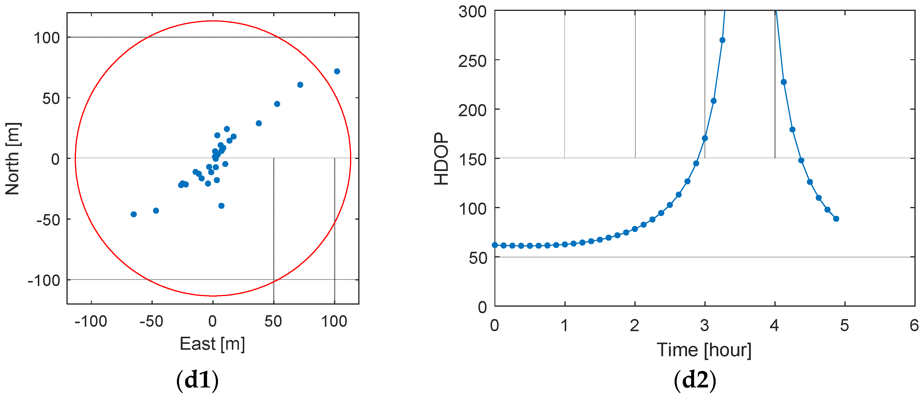
Prior to the MDPO demonstration, a double-differenced pseudorange error assessment was performed using all the visible GPS satellites. Major pseudorange errors, such as satellite and receiver clock offsets and ionospheric delay, can be effectively removed from the double-differenced observations and the remaining error would be basically the sum of pseudorange noises. Thus, the distribution of the relative position error depends entirely on the variance of the range error and the satellite geometry, and the 2 σ (95%) error of the double-differenced pseudorange observations can be obtained from the 2drms on the horizontal position errors and the corresponding HDOP values. The result showed that the expected 2 σ error of the double-differenced pseudorange observations was about 1 m.
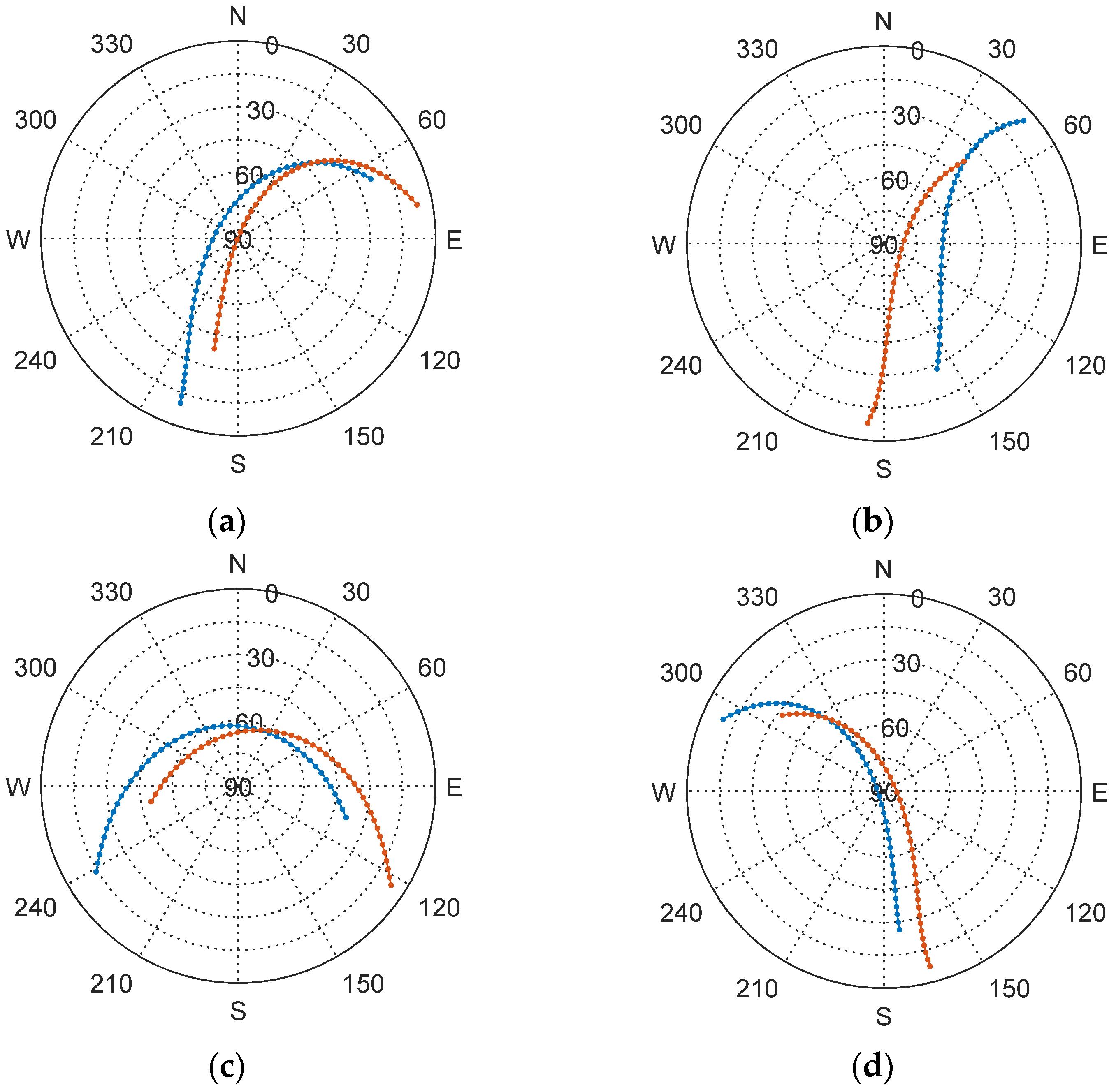
Next, we applied the MDPO algorithm using the same data set used in the double-differenced pseudorange error assessment. In this case, it was assumed that only two visible satellites were available at each epoch and four sets of satellite pairs were selected to emulate the satellite geometry resembling that of the previous lunar MDPO study. It was natural that the resulting horizontal positioning accuracies varied by satellite geometry, but the double-differenced pseudorange errors estimated from the 2drms of horizontal positioning errors and corresponding HDOP values were consistent and about 1 m. This agrees with the result of the previous double-differenced pseudorange error assessment, and it can be concluded that the MDPO algorithm worked properly with the real GPS observables and provided the expected performance.
Although the positioning accuracy of the MDPO algorithm tends to be lower because of its poor satellite geometry, it is still good enough for many lunar exploration activities. The MDPO algorithm is also suitable for the initial deployment stage of the lunar navigation satellite system because it only requires two satellites in view.
We are currently working on a design study of a lunar navigation satellite system using a pair of 6U-size CubeSats to demonstrate the MDPO algorithm on the Moon. More details of the satellite design will appear in our future article.

Author Contributions

Conceptualization, T.E. and T.T.; methodology, T.E.; software, T.E. and T.T.; validation, T.E.; formal analysis, T.E. and T.T.; investigation, T.E.; resources, T.T.; data curation, T.E.; writing—original draft preparation, T.E.; writing—review and editing, T.E.; visualization, T.E.; supervision, T.E.; project administration, T.E.; funding acquisition, T.E. All authors have read and agreed to the published version of the manuscript.

Funding

This work was supported by MEXT Coordination Funds for Promoting AeroSpace Utilization, Grant Number JPJ000959.

Data Availability Statement

Publicly available datasets were analyzed in this study. GNSS data in RINEX format can be found here: CDDIS [https://cddis.nasa.gov/, accessed on 28 September 2022].

Conflicts of Interest

The authors declare no conflict of interest.

References

  1. Johnson, K. Fly Me to the Moon: Worldwide Cislunar and Lunar Missions; Center for Strategic and International Studies: Washington, DC, USA, 2022. [Google Scholar]
  2. Paul, D.S. The Value of the Moon: How to Explore, Live, and Prosper in Space Using the Moon’s Resources; Smithsonian Books: Washington, DC, USA, 2016. [Google Scholar]
  3. Israel, D.J.; Mauldin, K.D.; Roberts, C.J.; Mitchell, J.W.; Pulkkinen, A.A.; La Vida, D.C.; Gramling, C.J. Lunanet: A flexible and extensible lunar exploration communications and navigation infrastructure. In Proceedings of the 2020 IEEE Aerospace Conference, Big Sky, MT, USA, 7–14 March 2020; pp. 1–14. [Google Scholar] [CrossRef]
  4. Giordano, P.; Malman, F.; Swinden, R.; Zoccarato, P.; Ventura-Traveset, J. The Lunar Pathfinder PNT Experiment and Moonlight Navigation Service: The Future of Lunar Position, Navigation and Timing. In Proceedings of the 2022 International Technical Meeting of The Institute of Navigation, Long Beach, CA, USA, 25–27 January 2022; pp. 632–642. [Google Scholar]
  5. Iiyama, K. Optimization of Navigation Satellite Constellation and Lunar Monitoring Station Arrangement for Lunar Global Navigation Satellite System (LGNSS). In Proceedings of the 32nd International Symposium on Space Technology and Science (ISTS), Fukui, Japan, 15–21 June 2019. [Google Scholar]
  6. Tanaka, T.; Ebinuma, T.; Nakasuka, S. Dual-Satellite Lunar Global Navigation System Using Multi-Epoch Double-Differenced Pseudorange Observations. Aerospace 2020, 7, 122. [Google Scholar] [CrossRef]
  7. Tanaka, T.; Ebinuma, T.; Nakasuka, S.; Malki, H. A Comparative Analysis of Multi-epoch Double-differenced Pseudorange Observation and Other Dual-Satellite Lunar Global Navigation Systems. Aerospace 2021, 8, 191. [Google Scholar] [CrossRef]
  8. The LROC Team Computed the Coordinates of China’s Chang’e 5 Lander. Available online: http://lroc.sese.asu.edu/posts/1172?fbclid=IwAR3fNoQuFQEmT6vSGh24yGPyRJAmpIfOln64IJCJg0bxC_A_dV6DNaCLJz0 (accessed on 10 September 2022).
  9. Kawabata, Y.; Kakihara, K.; Naresi, N.; Campagnola, S.; Ozaki, N.; Chikazawa, T.; Oguri, K.; Funase, R. Navigation Analysis for Launch and Early Operation Phase: EQUULEUS. In Proceedings of the 32nd International Symposium on Space Technology and Science (ISTS), Fukui, Japan, 15–21 June 2019. [Google Scholar]
  10. Ely, T.A.; Lieb, E. Constellations of elliptical inclined lunar orbits providing polar and global coverage. J. Astronaut. Sci. 2006, 54, 53–67. [Google Scholar] [CrossRef]
  11. Murata, M.; Kawano, I.; Kogure, S. Lunar Navigation Satellite System and Positioning Accuracy Evaluation. In Proceedings of the 2022 International Technical Meeting of The Institute of Navigation, Long Beach, CA, USA, 25–27 January 2022; pp. 582–586. [Google Scholar]
  12. Joseph, A. Measuring GNSS Signal Strength. Inside GNSS 2010, 5, 20–25. [Google Scholar]
  13. Bonetto, A.; Tirro, S.; Violi, V. System Outline. In Satellite Communication System Design; Tirro, S., Ed.; Springer: New York, NY, USA, 1993. [Google Scholar]
  14. Space Frequency Coordination Group. Communication and Positioning, Navigation, and Timing Frequency Allocations and Sharing in the Lunar Region. REC SFCG 32-2R3, 10 December 2021, pp. 1–9.
Figure 1. Relative positioning result using double-differenced pseudorange observations of all the visible GPS satellites: (a) the horizontal position errors; (b) the corresponding HDOP values.
Remotesensing 14 04856 g001
Figure 2. Phase angle between two satellites and angular travel during each observation period.
Remotesensing 14 04856 g002
Figure 3. Sky plots of the selected GPS satellite pairs: (a) PRN 01 and PRN 21; (b) PRN 12 and PRN 25; (c) PRN 16 and PRN 26; and (d) PRN 19 and PRN 17.
Remotesensing 14 04856 g003
Figure 4. Relative positioning results using MDPO algorithm: the horizontal position errors and the corresponding HDOP values with (a1,a2) PRN 01 and PRN21; (b1,b2) PRN 12 and PRN25; (c1,c2) PRN 16 and PRN26, and; (d1,d2) PRN 19 and PRN17.
Remotesensing 14 04856 g004aRemotesensing 14 04856 g004b
Figure 5. Parallel baseline motion of two GPS satellites in different orbital planes.
Remotesensing 14 04856 g005
Table 1. Selected GNSS stations and their locations.
IGS CodeSiteLatitude (deg)Longitude (deg)Elevation (m)
KGNIKoganei, Japan35.7013139.4881123.5
MTKAMitaka, Japan35.6795139.5614109.0
Table 2. The horizontal position errors and mean HDOP values.
2drms (m)Mean HDOP2drms/HDOP (m)
1.6181.6240.996
Table 3. Satellite orbital parameters used in the lunar MDPO simulation [6].
Orbital ElementsSatellite 1Satellite 2
Altitude 300   km
Inclination 0 °
Eccentricity 0.0
Right Ascension of the Ascending Node 0 °
Argument of Perilune 0 °
True Anomaly 0 ° 15 °
Table 4. MDPO horizontal position errors and mean HDOP values.
Satellite 1Satellite 22drms (m)Mean HDOP2drms/HDOP (m)
PRN 01PRN 2182.482.21.00
PRN 12PRN 25117.1112.01.05
PRN 16PRN 2639.943.60.91
PRN 19PRN 17113.3102.61.10
Table 5. Link budget analysis of the lunar MDPO signals.
ParametersValues
Propagation Distance, d 300 km1000 km
Transmitted Power, P T 0.2 W ( 7 dBW)
Frequency, f 2500 MHz
C / N 0 47.1 dB-Hz36.6 dB-Hz
Publisher’s Note: MDPI stays neutral with regard to jurisdictional claims in published maps and institutional affiliations.

