Article

Performance Analysis of BDS-3 SAIM and Enhancement Research on Autonomous Satellite Ephemeris Monitoring

1
Shanghai Key Laboratory of Navigation and Location-Based Services, Shanghai Jiao Tong University, 800 Dong Chuan Rd, Shanghai 200240, China
2
Beijing Institute of Tracking & Telecommunication Technology, Beijing 100094, China
3
General Institute of Navigation Satellites, Shanghai Engineering Center for Microsatellites, Shanghai 201304, China
4
Shanghai Key Laboratory of Space Navigation and Positioning Techniques, Shanghai Astronomical Observatory, Chinese Academy of Sciences, Shanghai 200030, China
5
Shanghai Astronomical Observatory, Chinese Academy of Sciences, Shanghai 200030, China
6
GNSS Research Center, Wuhan University, Luoyu Road No. 129, Wuhan 430079, China
7
China Academy of Space Technology, Beijing 100830, China
*
Author to whom correspondence should be addressed.
Remote Sens. 2022, 14(15), 3543; https://doi.org/10.3390/rs14153543
Submission received: 25 May 2022 / Revised: 7 July 2022 / Accepted: 19 July 2022 / Published: 24 July 2022
(This article belongs to the Special Issue Remote Sensing in Navigation: State-of-the-Art)

Abstract

:
Integrity is one of the key indicators used to characterize the performance of the global navigation satellite systems (GNSSs) and is closely related to user safety. In order to realize real-time global integrity monitoring, the BeiDou Global Navigation Satellite System (BDS-3) has realized the “satellite autonomous integrity monitoring” (SAIM) function in its satellites for the first time. BDS-3 SAIM has the monitoring functions of signal power, pseudo-range, satellite clock frequency and phase, but not the monitoring function of broadcast ephemeris. In this study, the long-term stability and distribution characteristics of BDS-3 SAIM monitoring data were analyzed by using the actual telemetry data for the first time. The results show that the SAIM monitoring data have good long-term stability and basically follow a normal distribution, which meets the design expectations. Meanwhile, in view of the fact that BDS-3 SAIM does not have the ability to independently monitor broadcast ephemerides, which may lead to the over-tolerance of BDS-3 to the probability risk of risks of integrity in the active space environment, a SAIM enhancement design for ephemeris monitoring is proposed, which integrates three relatively independent methods, with the ephemeris extrapolated from the previous cycle, and the ephemeris generated by autonomous orbit determination, inter-satellite link distance measurement data as reference data, respectively. The three methods are analyzed and verified. The results show that each of the three methods has advantages and disadvantages in terms of monitoring accuracy and resource dependence. The integration of the three methods can combine their complementary advantages and can also provide valuable as an important reference for engineering applications.

Graphical Abstract

1. Introduction

With the wide application of satellite navigation systems in many real-time fields such as aviation, high-speed railways and unmanned vehicles, users’ demand for reliable GNSS has increased [1]. The integrity of GNSS is an important indicator used to measure the reliability of a system’s service. It refers to the ability of the system to provide a timely alarm to users when any fault or error in the GNSS exceeds the allowable limit [2,3]. With improvements in service accuracy, the “Big 4” GNSS (GPS/BDS/Galileo/GLONASS) are all paying more and more attention to improving their system integrity monitoring ability. In the Big 4 GNSS upgrade plans, improving the system’s integrity service ability is one of the most pressing concerns [4,5,6].
At present, the GNSS integrity monitoring methods can mainly be divided into satellite autonomous integrity monitoring (SAIM), ground integrity monitoring and receiver autonomous integrity monitoring (RAIM) [7]. Among these, RAIM technology refers to the detection, analysis and processing of service performance anomalies by the user receiver of the received observations of multiple navigation satellites [8]. Generally, this technology can only monitor the obvious anomalies of a single satellite. Ground integrity monitoring technology refers to monitoring the accuracy of the spatial signal corresponding to the predicted ephemeris and clock error in the navigation message by using the observation data of the monitoring station established by the system and obtaining the corresponding integrity parameters and broadcasting them to the user together with the navigation message [5]. There is also an article examining the concept of relative receiver autonomous integrity monitoring (RRAIM) where using time differential carrier phase measurements is investigated [9]. SAIM technology involves the monitoring of the satellite’s anomaly by the navigation satellite itself. Thus, SAIM could work independently, without being affected by ground equipment and propagation path errors, which has the advantage of highly efficient alarm times, and it is an important development direction of monitoring GNSS integrity [10,11,12,13]. Study [14] mentions the use of inter-satellite link communication information to enhance SAIM monitoring capabilities. Study [15] describes an approach to SAIM and is prototyping it. The prototype has been tested against nominal satellite signals (to confirm that no fault alarms are rare enough to support civil aviation continuity requirements) and several classes of fault signals. Practical implementation issues such as satellite multipath and receiver clock calibration will also be addressed. This method can be applied to future GNSS satellites such as GPS III. Study [16] focuses on the technical solution of BDS-3’s SAIM, analyzes the complete telemetry data of the new generation of Beidou satellites, and confirms that the alarm time through message is less than 6 s, and the alarm time through non-standard code (NSC) is less than 2 s.
In the first GPS designs, SAIM was not fully considered, with most integrity indicators not meeting International Civil Aviation Organization (ICAO) requirements. In order to meet the needs of the civil aviation industry for integrity, many countries and regions have established satellite-based augmentation systems (SBAS) and ground-based augmentation systems (GBAS) to compensate for the lack of GPS integrity monitoring capability. GPS III also plans to enhance the risk controlling ability of ground control systems, to increase the ability of SAIM and to redesign the integrity parameters, thus ensuring that the probability of integrity risk in the system meets the index required by the ICAO, which is better than 10−7/h. The latest service performance specifications show that the global integrity alarm time of GPS is less than 10 s. The Galileo system is also carrying out SAIM research via the simulation analysis method [11,12].
Due to some objective factors, such as geographical politics, the monitoring coverage of the BDS-3 ground monitoring network for on-orbit satellites is limited. Ground integrity monitoring alone cannot meet the needs of global monitoring. Faced with this problem, BDS-3 has engineered the first realization of SAIM for all constellation satellites all around the world, and the alarm time performance is theoretically better than 6 s. Fusion of the information of SAIM and ground integrity monitoring can achieve global coverage and a timely response for integrity monitoring, thus ensuring the integrity of the service ability of the system [17,18].
BDS-3 SAIM already has the ability to monitor the satellites’ atomic clock frequency, the satellites’ atomic clock phase, the downlink navigation signal power and the pseudo-range measurement, but it does not have the capacity for autonomous monitoring of satellite ephemeris. At present, the monitoring of ephemeris anomalies relies only on ground monitoring stations, which also means that when the satellite runs in the arc section outside the area covered by the ground monitoring stations, every time an ephemeris anomaly occurs, the alarm will be completely missed; that is, the user will receive the wrong navigation information but BDS-3 will not send an effective and timely warning to the user. As BDS-3 only has a few monitoring resources outside of China, a satellite ephemeris anomaly occurring outside China is likely to be one of the most important risks to the integrity of BDS-3’s service [19]. Therefore, supplementing and enhancing the autonomous integrity monitoring ability for satellite ephemeris anomalies has become an important part of upgrading BDS-3.
According to studies [18,19], during the two-year period from 27 December 2018 to 27 December 2020, six SAIM misses occurred in BDS-3 (the main reason was that SAIM did not have the ability to monitor the ephemeris anomalies), and the probability of an integrity risk obtained by the final evaluation was about 0.9 × 10⁻⁷, which only just meets the index requirement of 1.0 × 10⁻⁷. Therefore, in order to ensure that BDS-3 can still meet the requirements of the integrity indicators required by the ICAO for the future period of a more severe space environment, it is very necessary to carry out research on how to enhance SAIM’s capability to monitor ephemerides.
To sum up, this paper firstly describes the BDS-3 SAIM design scheme, including current SAIM monitoring methods of signal power, pseudo-range, clock frequency and phase. In view of the lack of autonomous ephemeris monitoring capability of BDS-3 SAIM, an enhancement design is proposed, which consists of three relatively independent methods. Then, using the actual telemetry data of BDS-3 satellite on-orbit, the actual performances of current SAIM in navigation signal power, pseudo-range measurement, satellite atomic clock frequency jump monitoring and phase jump monitoring are quantitatively analyzed. According to the analysis results, we obtained the actual characteristics of SAIM monitoring data. Meanwhile, the validity and feasibility of the ephemeris monitoring methods are verified by simulation data, which ensures that the method can provide direct and effective support for the realization and application of SAIM in the near future.

2. BDS-3 SAIM Monitoring Method

2.1. Current Monitoring Methods

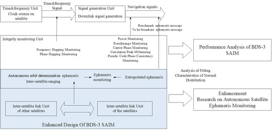
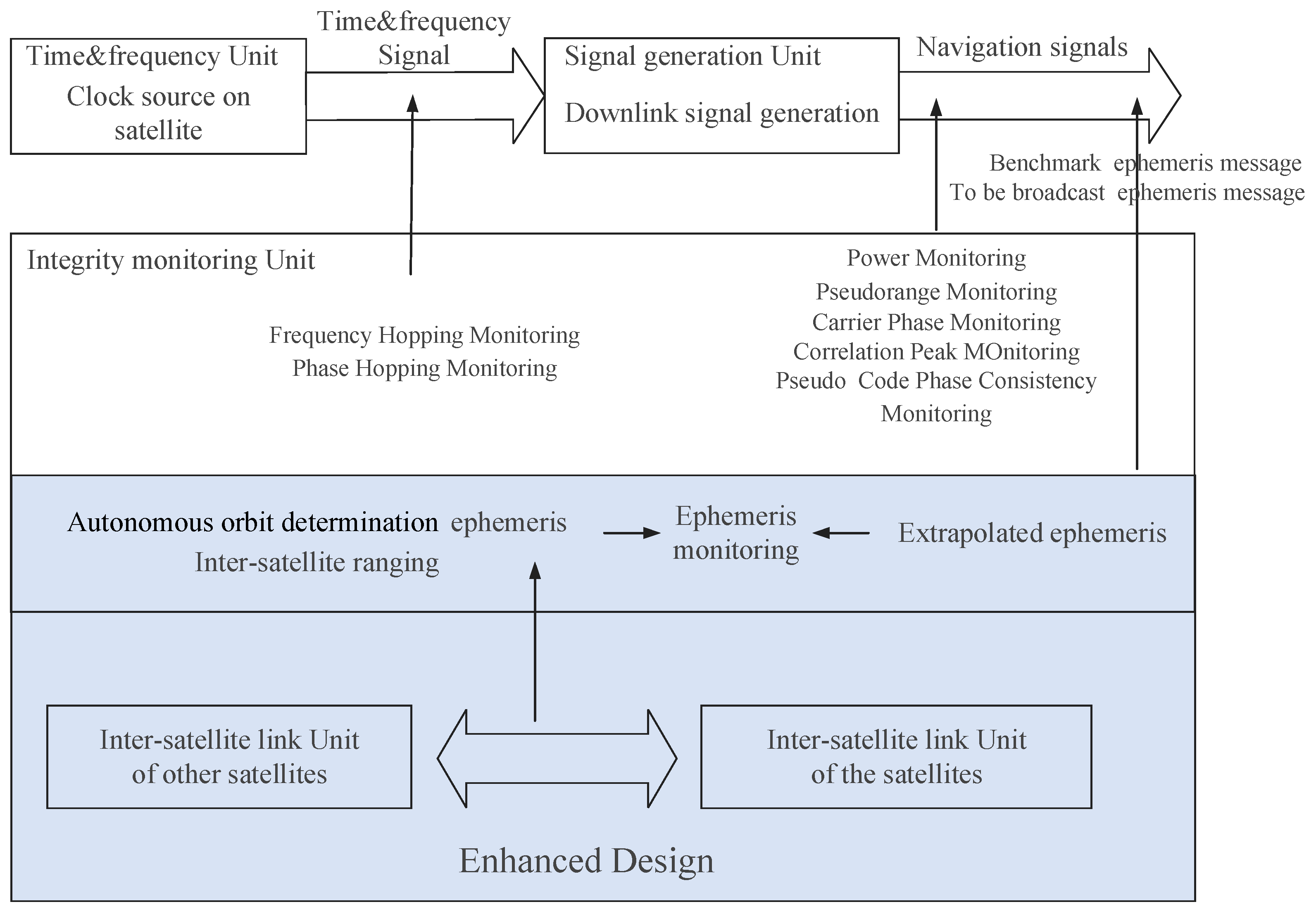
BDS-3 SAIM monitors the health status of navigation signals and satellite clocks by continuously monitoring its own broadcast signals from navigation satellites. SAIM includes downlink navigation signal quality monitoring and time-frequency stability monitoring. Among these, downlink navigation signal quality monitoring involves monitoring of the signal power, the pseudo-range, code phase consistency and the correlation value. Time-frequency stability monitoring involves monitoring of the frequency hopping and phase hopping of the satellite’s atomic clocks. Finally, the integrity information of the navigation signal is generated by integrating the monitoring information of the satellite’s atomic clock and navigation signal [7].
The downlink navigation signal quality monitoring function of SAIM is to identify the abnormal situation of the carrier to noise density of the user receiver caused by the decrease of the navigation signal power through power monitoring; through pseudo-range monitoring, identify the abnormal jump of the pseudo-range observed by the user. Moreover, due to the different paths used for generating the frequency signal of the pseudo-range and carrier phase on the satellite, if any path produces an anomaly, the pseudo-range and carrier phase will be inconsistent, which would affect the high-precision positioning of users. Therefore, such anomalies can be identified by monitoring the code phase consistency. Correlation peak monitoring [18] uses three pairs of narrow correlators to obtain three pairs of correlation values, monitor the symmetry of the signal correlation peak and realize the monitoring of the signal’s pseudo-range deviation. At present, the code phase consistency monitoring and correlation peak monitoring algorithms are still in the on-orbit test phase and have not yet actually been involved in monitoring the integrity of the system. The time-frequency stability monitoring function of SAIM monitors the stability of the satellite’s atomic clock by monitoring the frequency and phase jump of the satellite clock.
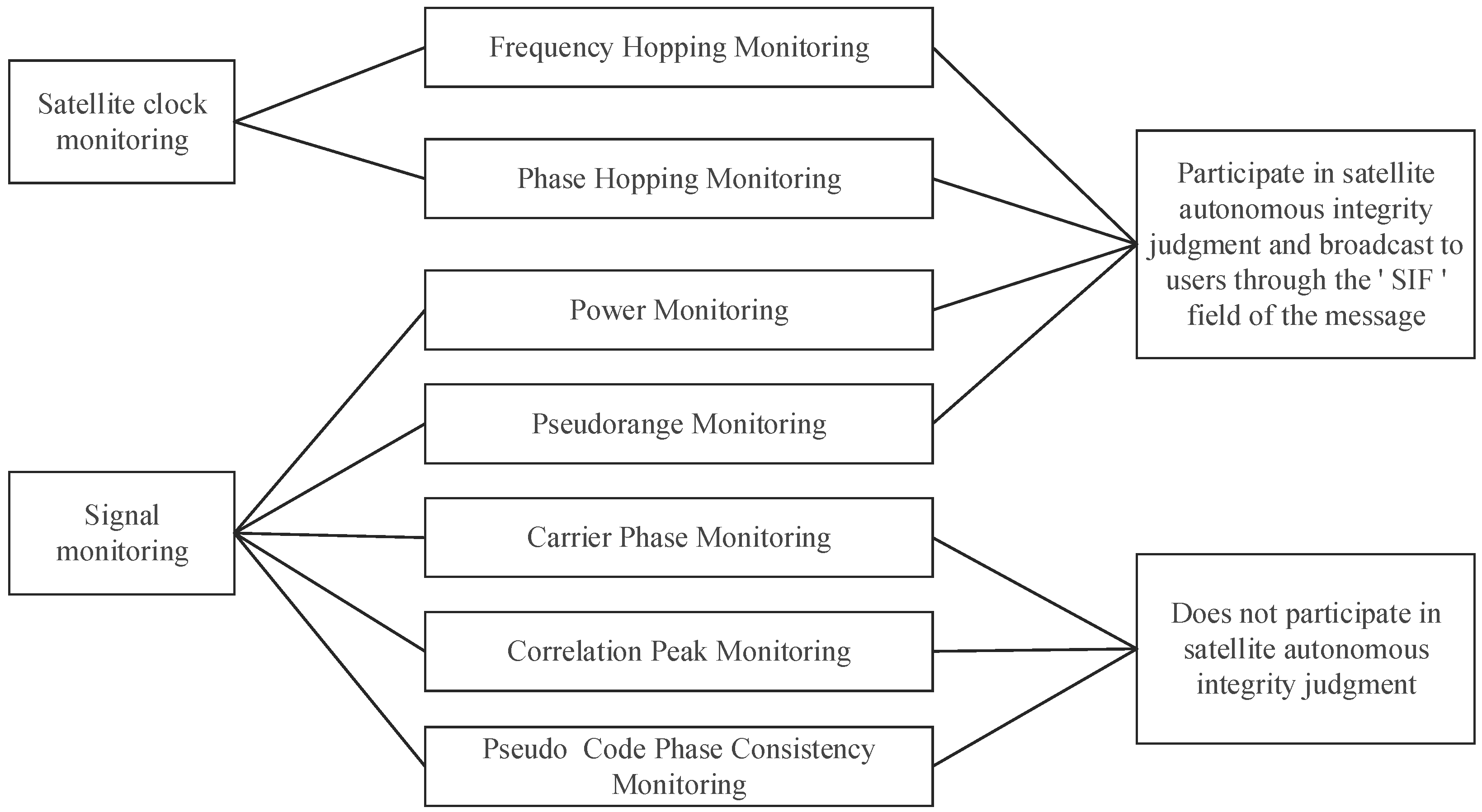
Due to the absence of propagation and environmental errors and noise, SAIM monitoring data usually fluctuate around a certain mean. If the navigation signal is abnormal, resulting in an abnormal jump in some monitoring data that exceeds the alarm threshold, SAIM will issue an alarm for that navigation signal. SAIM alarm modes consist of the message integrity alarm mode and the non-standard code integrity alarm mode. In the message integrity alarm mode, if SAIM detects an anomaly, the satellite will set the signal integrity flag (‘SIF’) parameter in the signal navigation telegram as ‘1’ independently. After rectification of the anomaly has been confirmed by the ground system, the ‘SIF’ parameter will be reset to ‘0’. In non-standard code alarm mode, if SAIM detects an anomaly, the satellite will independently switch the spread spectrum code of the signal to the non-standard code, so that the user cannot receive the navigation signal. The current SAIM used on BDS-3 satellites is show in Figure 1.

2.1.1. Signal Power Monitoring

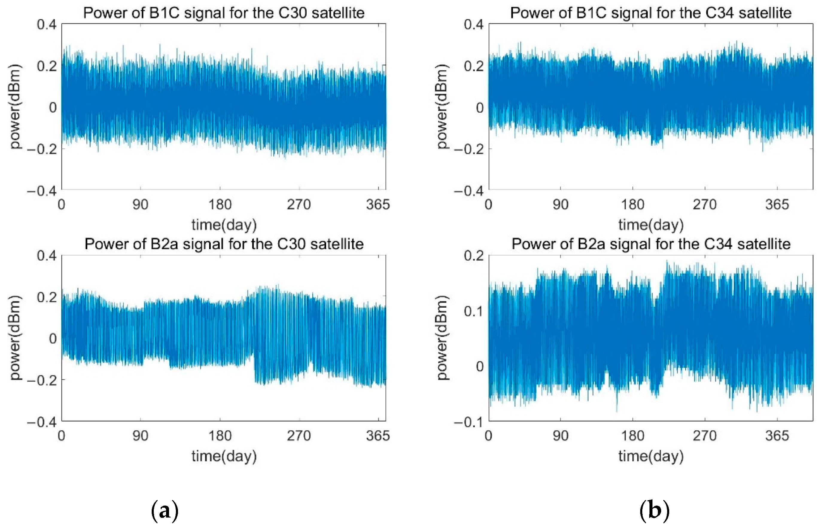
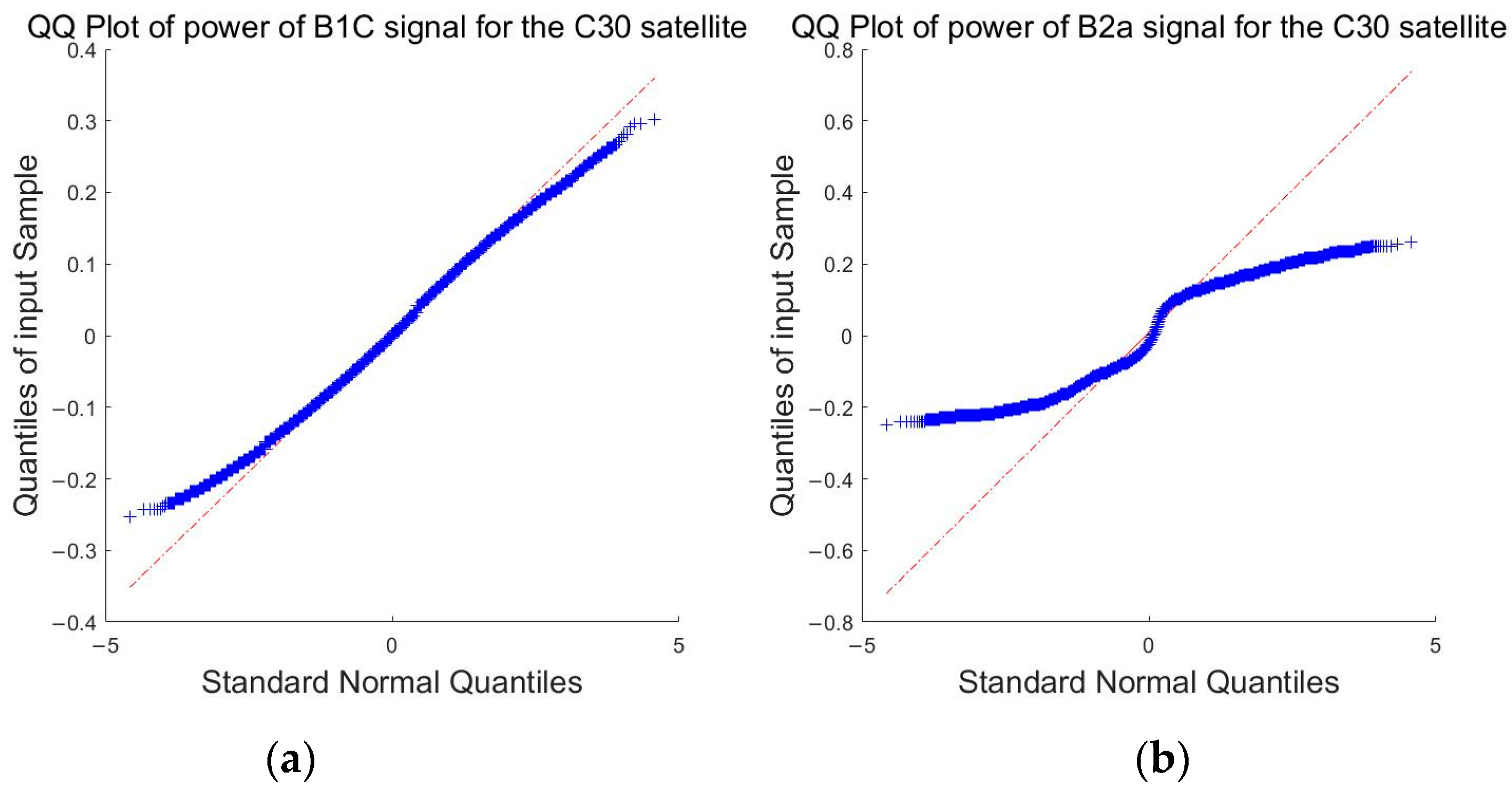
In the front of the downlink navigation transmitting antenna of the navigation satellite, the low power signal is obtained by coupling as the input signal of the SAIM function unit. Based on the power monitoring information collected by the signal processing module, the navigation signal’s quality is monitored and evaluated by the power of the satellite’s signal. Normally, the signal power monitored for a satellite should fluctuate within a certain range around the mean value. Once the navigation signal’s power drops beyond the alarm threshold, SAIM will issue an alarm. The SAIM alarm threshold usually has an initial empirical value. Under normal signal conditions, the on-orbit signal power monitoring data should have high stability.

2.1.2. Pseudo-Range Monitoring

Satellite load anomalies may cause abnormal jumps in the pseudo-range measurements received by the user receiver. Since the monitoring unit can adopt different frequency sources for the satellite’s atomic clock, the pseudo-range measurement value of the satellite’s autonomous monitoring usually has a linear drift. By increasing the corresponding linear compensation, the pseudo-range measurement value of the satellite’s autonomous monitoring can fluctuate within a certain range around the mean value. If an abnormal jump is found in the pseudo-range of a certain navigation signal and exceeds the alarm threshold, the alarm information of the signal is given.

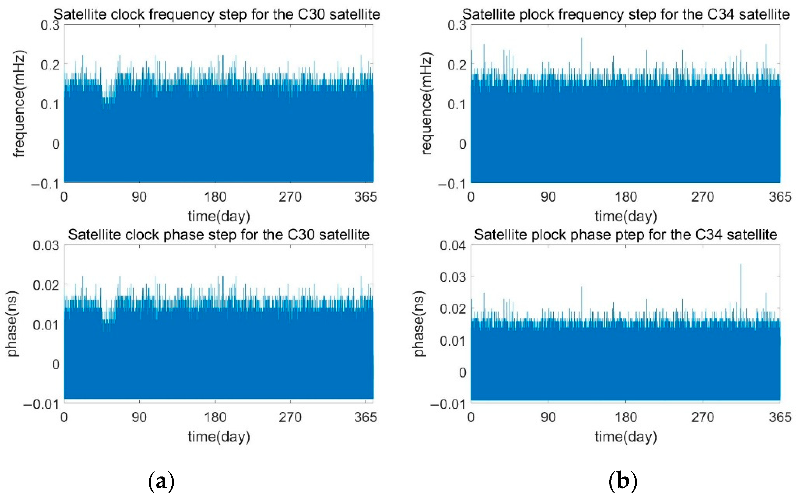
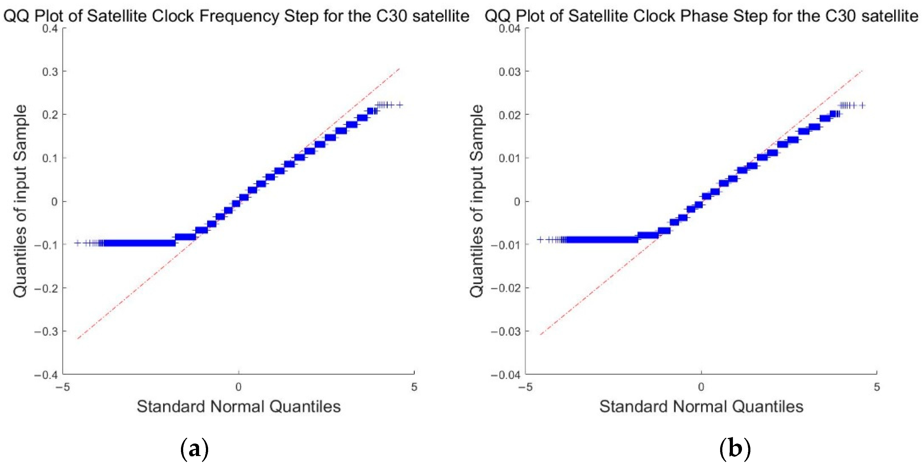
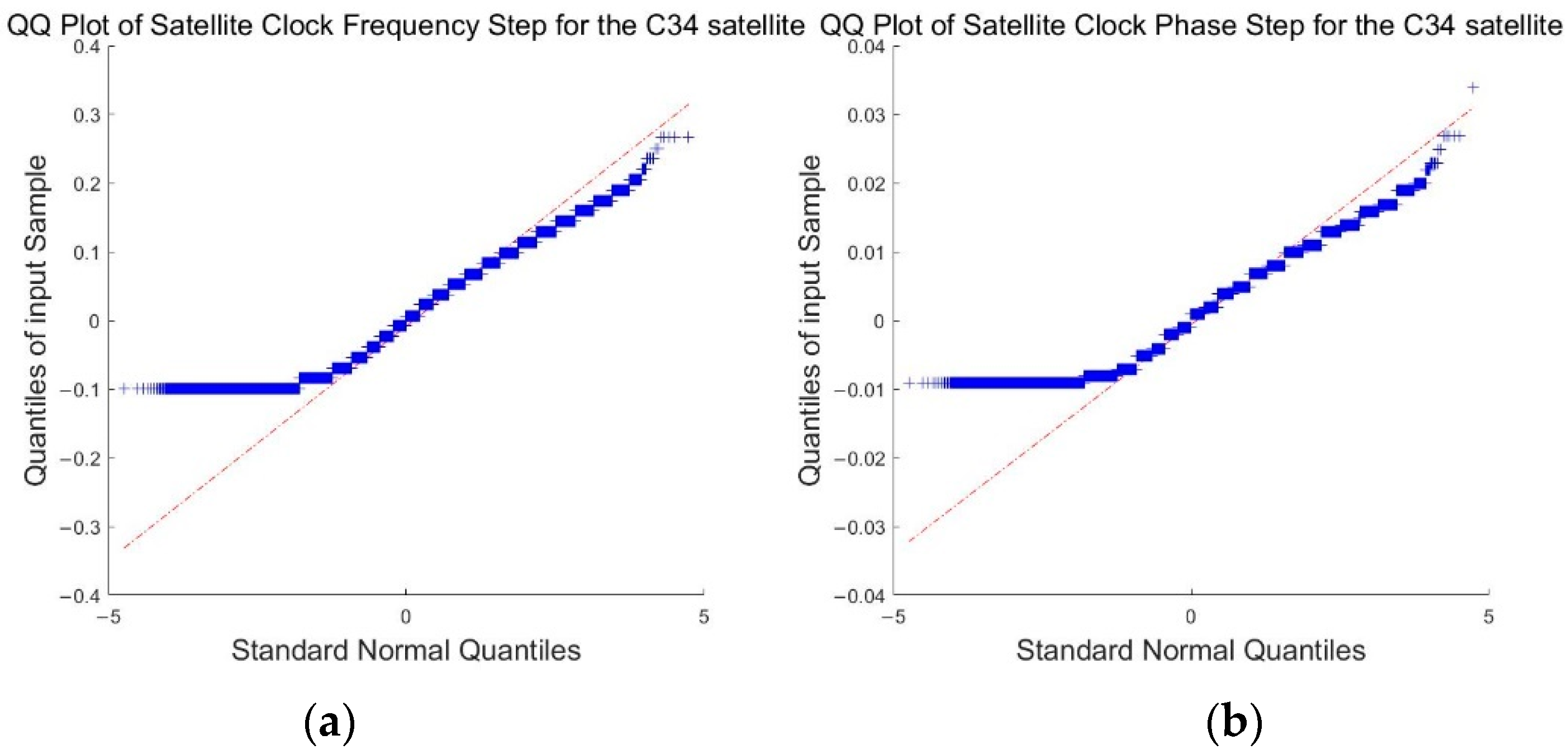
2.1.3. Satellite Clock Frequency and Phase Hopping Monitoring

The autonomous monitoring of the frequency hopping and phase hopping of the satellite clock is realized by a loop phase tracking system, which adjusts the frequency and phase of the local signal through negative feedback to track the reference signal. The phase shift introduced by the difference in frequency between the satellite clock and the local reference crystal oscillator can be eliminated by the secondary difference of the measured value of the adjacent epoch clock difference, and the phase hopping of the satellite clock can thus be monitored. The satellite clock frequency hopping can be derived from the phase hopping. If either the satellite clock phase or the frequency hopping exceeds the preset alarm threshold, SAIM will issue an alarm.

2.2. Enhanced Ephemeris Monitoring Methods

Until now, BDS-3 SAIM has not been able to monitor ephemeris anomalies in broadcast messages. The ephemeris anomaly monitoring scheme presented below can effectively fill this gap and further strengthen the on-orbit autonomous monitoring capability of BDS-3.
The generation, update and broadcast mode of the navigation ephemeris message is as follows: the ground operation management center collects the observation data of the navigation satellite’s downlink signal, processes the data uniformly, determines the satellite’s orbit and calculates the clock error. Next, the long-term navigation ephemeris is injected into the whole network satellite at a fixed time per hour for a period of time in the future. When the satellite needs to broadcast the navigation message, it retrieves the reference time of each group of navigation messages according to the current time, and a combination of the closest reference time and the current time is selected to send to the signal’s downlink broadcast module to broadcast to the ground. Since there is little difference between the preceding and the following hour ephemeris, the current hour can be used to check the next hour.
The ephemeris of a satellite is composed of 18 quasi-Kepler orbital parameters and the ephemeris data age, with a total of 454 bits in each group. The format of the ephemeris is the same as that of the uplink injection at the ground station. The ephemeris mainly includes: issue of data ephemeris, the ephemeris reference time, the orbit type of satellite, the deviation of the semi-major axis contrast to the reference value, the semi-major axis change rate, the difference between the average speed of the satellite and the calculated value, the rate of change of the difference between the average speed of the satellite and the calculated value, mean anomaly at the reference time, the eccentric rate e, the amplitude of the near-earth point, the reference longitude of the ascending anode, the orbital inclination at the reference time, the variable quantity of the ascending node’s right ascension rate of change, the change rate of orbital inclination and orbit inclination, the radius, and the latitude amplitude angle of the sine, cosine harmonic correction term, etc.
It is meaningless to make a simple threshold judgment for each separate parameter of an ephemeris message. The latest array of ephemeris messages should be transformed to obtain a set of one-dimensional results. According to the distribution characteristics of the parameter pairs and the safety requirements of engineering monitoring, a reasonable error threshold is set to judge the rationality of the ephemeris message parameters.
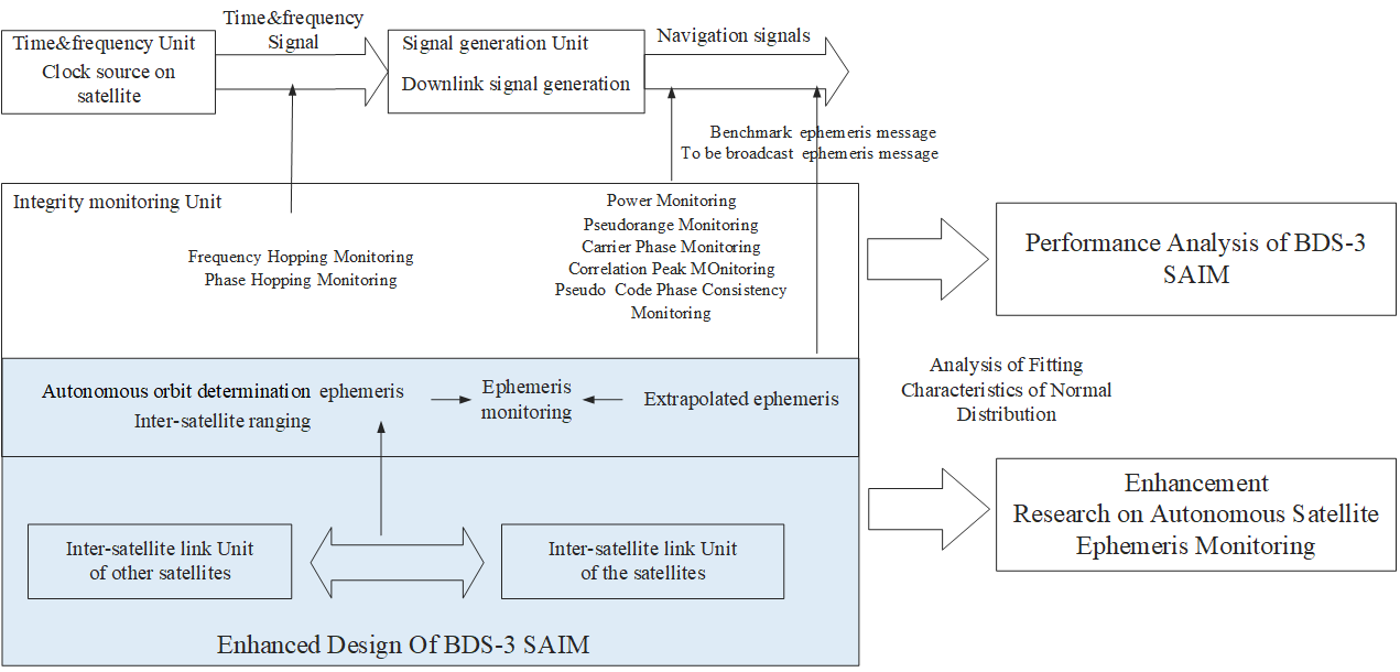
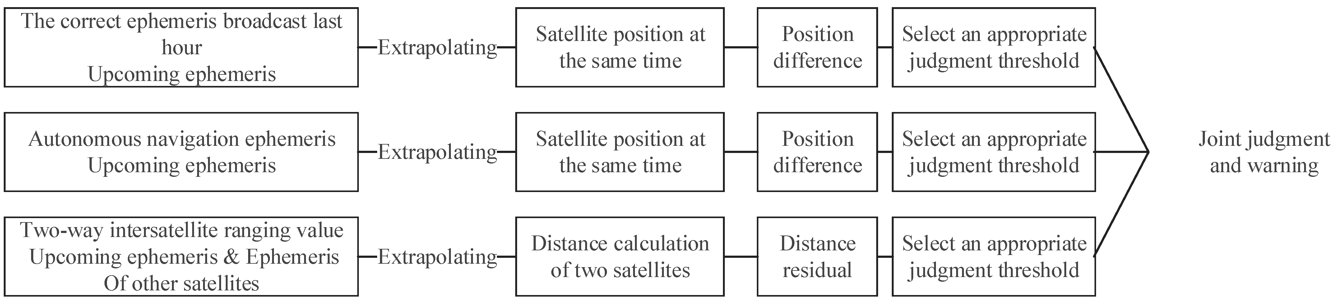
In order to realize autonomous integrity monitoring of ephemeris, we propose a SAIM enhancement design, which consists of three relatively independent methods. In essence, no matter which method, an additional reference benchmark is needed to compare with the ephemeris received by the satellite at the current time in order to achieve the monitoring of ephemeris. If the difference exceeds the alarm threshold, an alarm would be output. The reference data of the three methods are respectively: (1) the ephemeris extrapolated from the previous cycle; (2) the ephemeris generated by autonomous orbit determination; (3) inter-satellite link distance measurement data. The specific comparison process is shown in Figure 2.
Figure 3 shows the new SAIM design with additional ephemeris message integrity monitoring. In order to reduce the false alarm probability of ephemeris integrity messages, it is necessary to use a combination of monitoring methods to produce an alarm. SAIM will send an alarm only when the monitoring results of at least two of these monitoring methods exceed the alarm threshold, and the satellite will set the “SIF” parameter in the broadcast ephemeris from “0” to “1” to ensure that the alarm messages are broadcast to the users.

2.2.1. Extrapolated Ephemeris

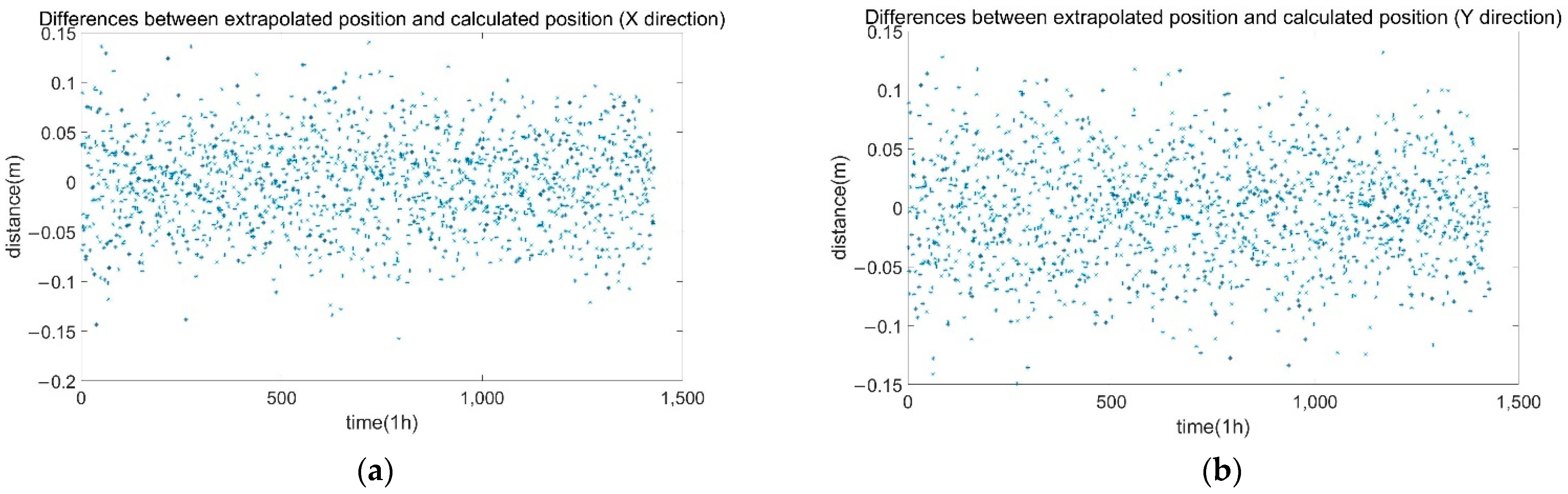
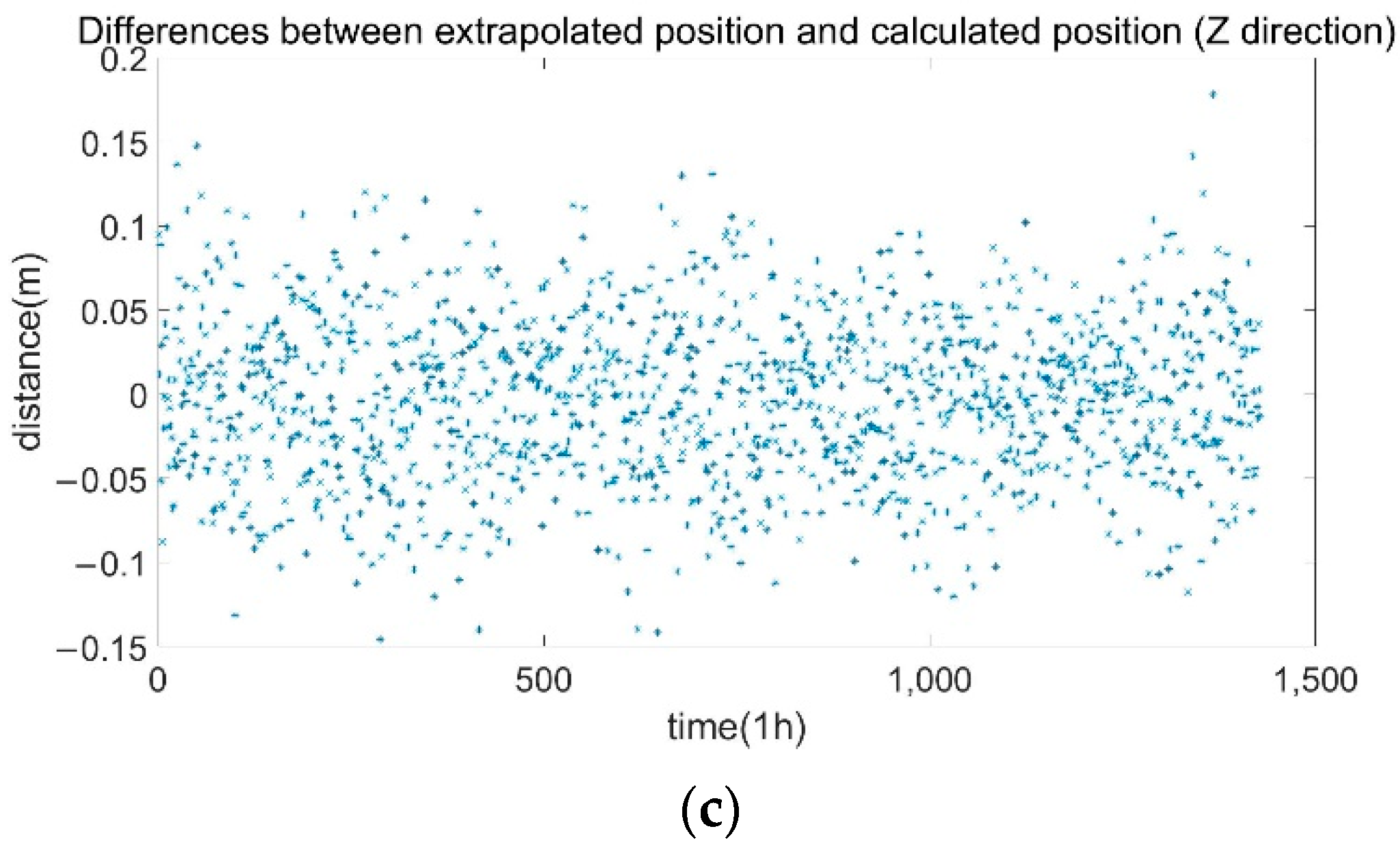
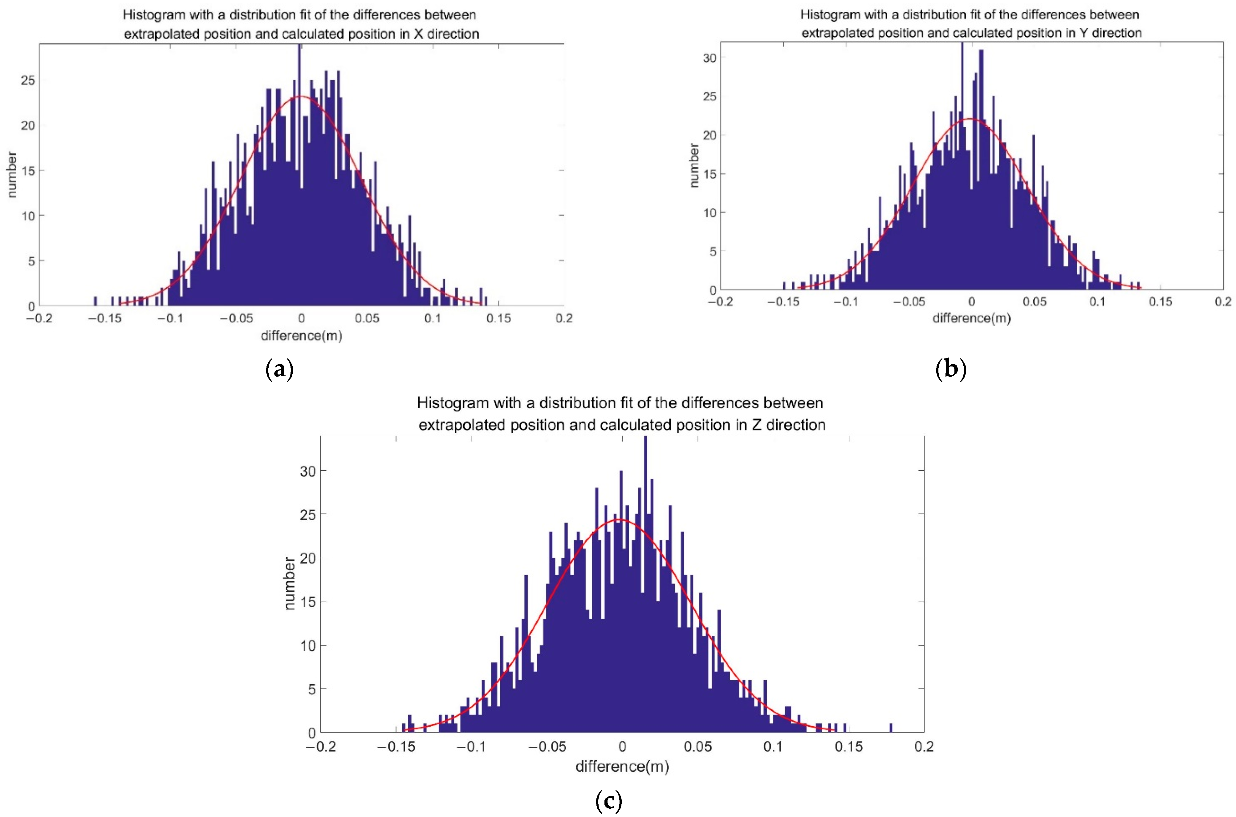
In BDS-3, the ground control system injects the broadcast ephemeris to the satellite once every hour. After receiving the latest broadcast ephemeris, the satellite can use the navigation ephemeris message posted from the ground station in the previous hour to calculate the position predicted by the two groups of ephemeris messages for the same time and to calculate the satellite’s position difference calculated from the two ephemerides. If the position difference exceeds the threshold, an alarm will be given through SAIM to monitor the orbit of the navigation message and prevent the wrong ephemeris from being received by the users, even when the satellite receives the wrong ephemeris. The method of extrapolating satellite position using ephemeris can refer to BeiDou Navigation Satellite System Signal in Space Interface Control Document Open Service Signal B1C (Version 1.0) [20].
Usually, the forecast error of the satellite’s broadcast ephemeris for 1 h is at the decimeter level, which can be used as a reference for monitoring the newly posted broadcast ephemeris. The monitoring method is simple, effective and reliable.

2.2.2. Autonomous Orbit Determination Ephemeris

The Beidou-3 satellite is equipped with an autonomous orbit determination function unit, which has the ability to operate independently and generate ephemeris independently, and run in parallel with the navigation signal generation unit. Among them, the autonomous orbit determination function unit mainly relies on the inter-satellite link to generate ephemeris information, and the navigation signal generation unit mainly relies on the ground annotation to generate ephemeris information. Therefore, the ephemeris information generated by the two units is relatively independent and can be used as a comparison to monitor the correctness of the ephemeris to be broadcast.
According to the user’s algorithm of the downlink ephemeris (refer to BeiDou Navigation Satellite System Signal In Space Interface Control Document Open Service Signal B1C (Version 1.0) [
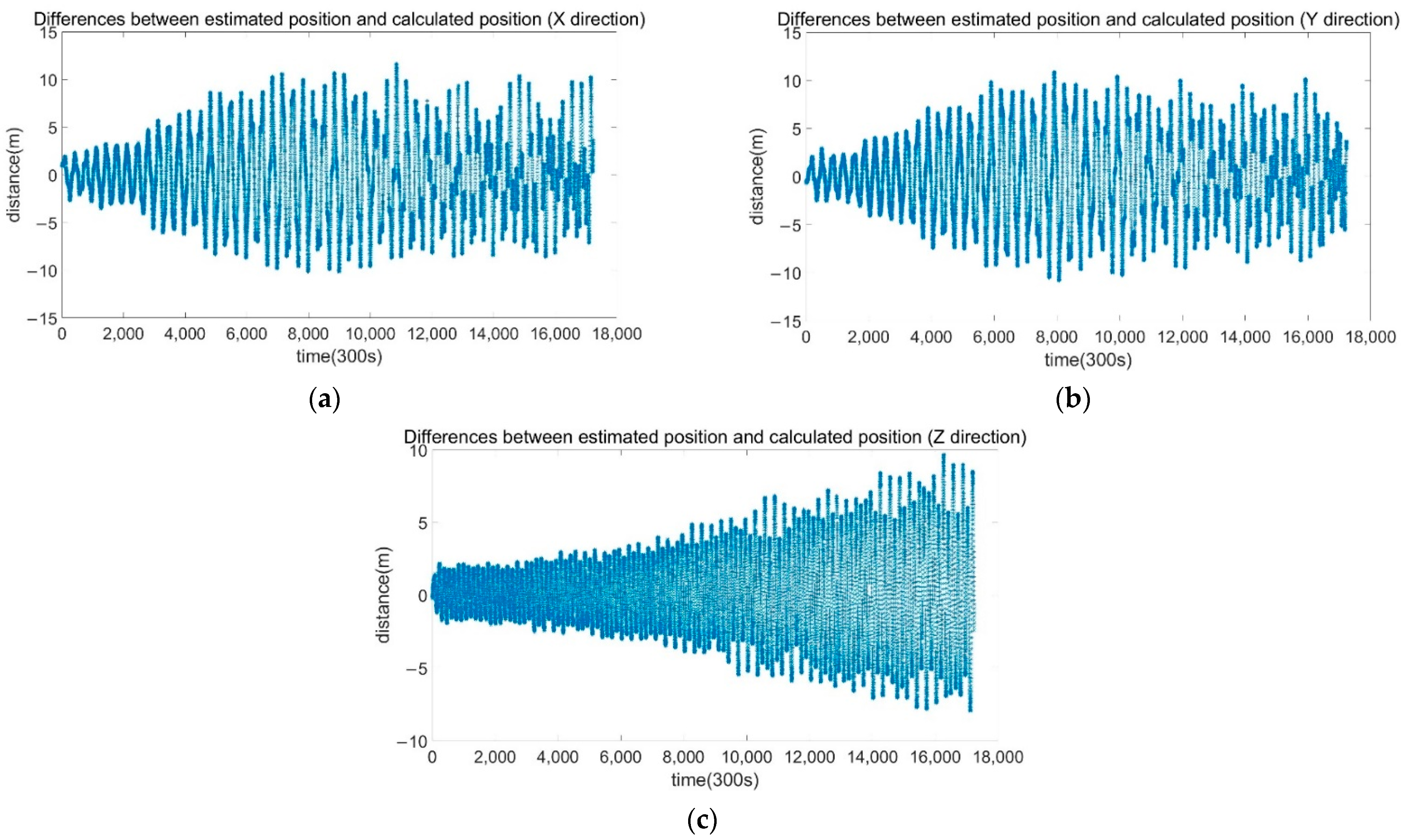
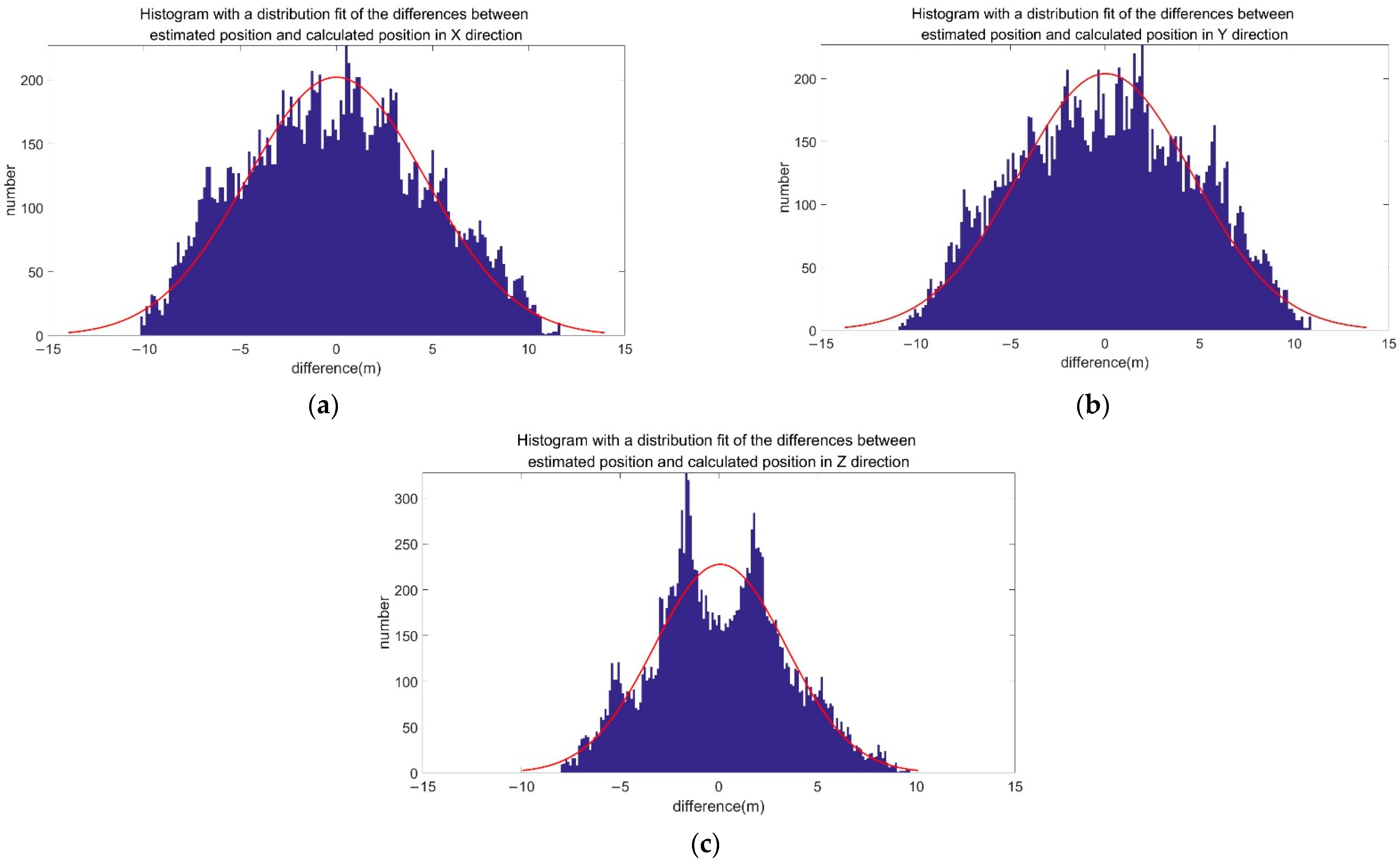
20] for the specific algorithm), we can calculate the position of the BDS-3 MEO satellite in the X, Y, and Z directions in the BeiDou coordinate system (BDCS), and compare the ephemeris message to be broadcast and the autonomous orbit determination message at the same time. The difference between the obtained positions is compared with the threshold to confirm the correctness of the ephemeris message to be broadcast in the next hour. If it is greater than the judgment threshold, an alarm will be issued.
The autonomous orbit determination message can be used to realize the monitoring of the ephemeris parameters when the satellite is in the on-orbit autonomous operation state, but the accuracy will be lower than that of using the uplink posted message, and with an extension of the running time of the autonomous operation state, the accuracy will be further reduced, which is expected to be in the order of 10 m.

2.2.3. Inter-Satellite Ranging

The BDS-3 has inter-satellite link observation data, which can also be used as a reference for judging the integrity of ephemeris messages. 
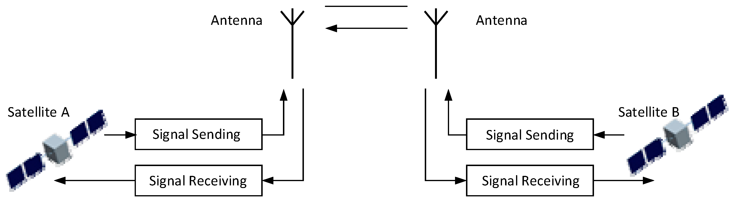
Figure 4 shows a schematic diagram of the two-way ranging of the inter-satellite link.
If we assume that A is the satellite to be monitored, and there is an inter-satellite link ranging between B and A, the inter-satellite link ranging between A and B can be expressed as [21]:
ρ A B t 1 = R B t 1 R A t 1 Δ t 1 + c c l k B t 1 c l k A t 1 + τ A S e n d + τ B R c v + Δ ρ c o r A B , ρ A B t 2 = R B t 2 R A t 2 Δ t 2 + c c l k A t 2 c l k B t 2 + τ A R c v + τ B S e n d + Δ ρ c o r A B
In the Formula (1), t 1 and t 2 are the different moments; R i is the satellite’s position vector; Δ t i is the transmission delay for ranging; c l k i is the satellite clock; τ i S e n d and τ i R c v are the delays of the transmitting and receiving equipment, respectively; Δ ρ c o r A B is the combined error of the ranging observation error, the satellite orbit error and the satellite clock error.
To obtain the two-way distance observations, the one-way observations need to be reduced to the same moment, and the reduction equation is shown in the following formula:
ρ A B t 0 = ρ A B t 1 + d ρ A B = R B t 0 R A t 0 + c c l k B t 0 c l k A t 0 + τ A S e n d + τ B R c v + Δ ρ c o r A B , ρ A B t 0 = ρ B A t 2 + d ρ B A = R A t 0 R B t 0 + c c l k A t 0 c l k B t 0 + τ A R c v + τ B S e n d + Δ ρ c o r A B
where d ρ A B and d ρ B A represent the amount of reduction correction calculated from the observation time and the reduction time, which are related to the distance difference and the clock difference between the reduction time and the observation time; d ρ A B and d ρ B A are calculated by the following formula:
d ρ A B = R B t 0 R A t 0 R B t 1 R A t 1 Δ t 1 + c c l k B t 1 c l k A t 1 c c l k B t 0 c l k A t 0 , d ρ B A = R B t 0 R A t 0 R B t 2 R A t 2 Δ t 2 + c c l k A t 2 c l k B t 2 c c l k A t 0 c l k B t 0
d ρ A B and d ρ B A can be calculated by the differences in the satellite forecast orbit and forecast clock parameters, and its calculation accuracy determines the reduction accuracy of the time-division system’s inter-satellite ranging data, which depend on the satellites’ forecast clock speed accuracy and speed forecast accuracy. A pair of satellites generally completes a two-way measurement within 3 s. Therefore, in the previous algorithm, the target time is reduced to a distance t 0 from the observation times t 1 and t 2 that is less than 3 s. At present, the BDS-3 satellite’s speed forecast error is about 0.1 mm/s and the forecast clock speed error is less than 1 × 10⁻¹³ s/s. The time interval for imputation is 3 s. Thus, it can be calculated that the reduction error of 3 s is less than 0.0003 ns, which is negligible for judging the ephemeris error.
ρ A B t 0 
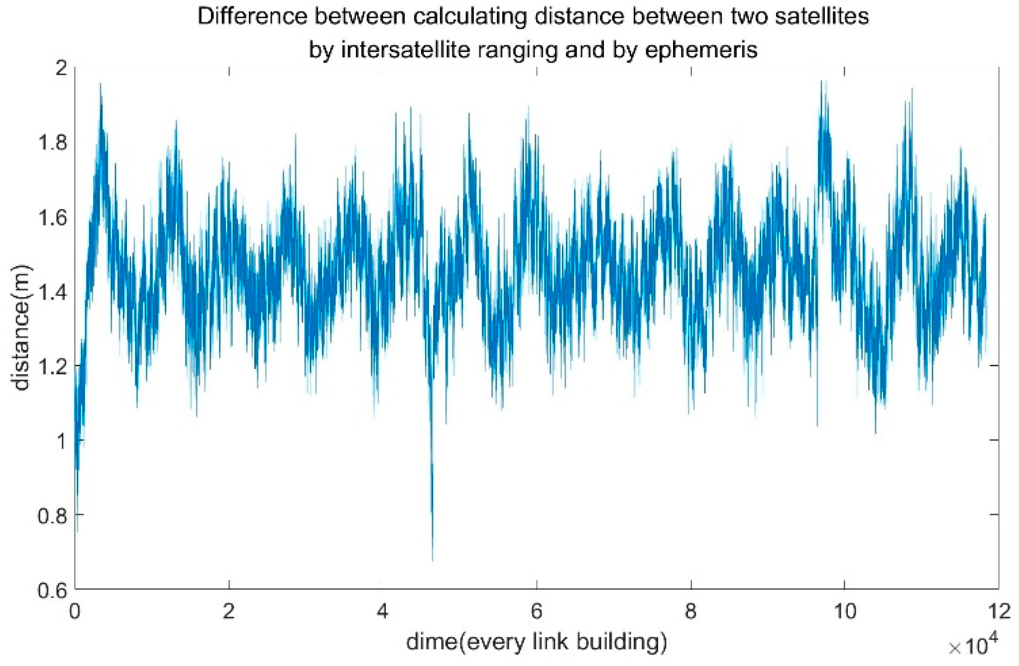
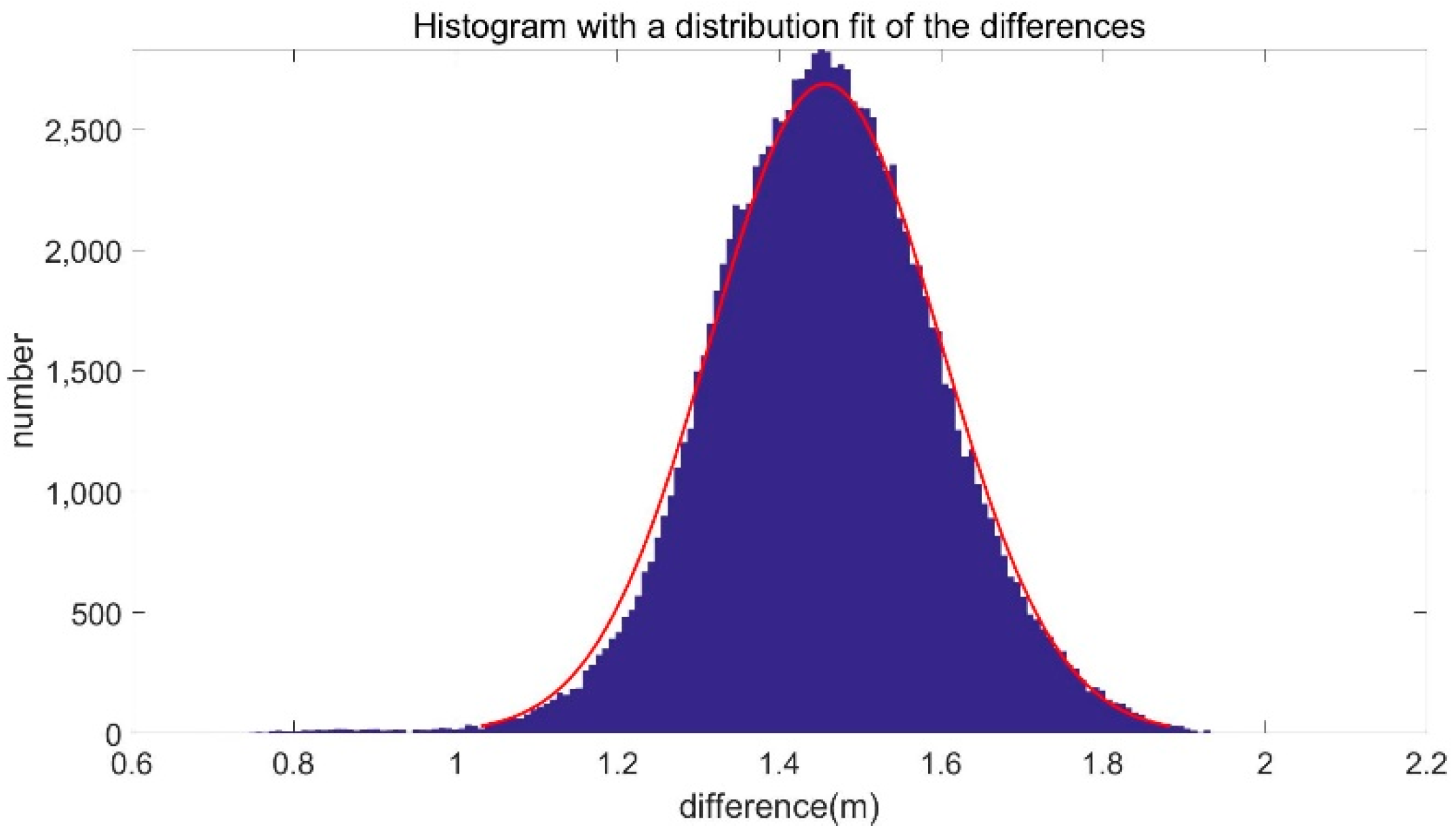
can be measured simultaneously in Formula (2) before they are added together and the clock error parameters are eliminated to obtain the geometric distance. The measured value is used to find the difference in the geometric distance calculated by using the broadcast ephemeris to obtain the distance between two satellites and ultimately obtain the inter-satellite link’s ranging residual, which can be used to judge whether the ephemeris of the two satellites is normal. If the ephemeris of Satellite A or Satellite B is abnormal, the ranging residual will increase. Since it is impossible to determine whether the faulty satellite is Satellite A or Satellite B, it is necessary to use the ranging residuals of at least two other satellites for a comprehensive judgment to identify the faulty satellite.

3. Results and Discussion

3.1. Performance of BDS-3 SAIM Based on On-Orbit Data

With the actual SAIM telemetry data of the BDS-3 on-orbit satellites, taking the data of the C30 and C34 satellites for the full year 2021 as examples, the variation in the characteristics and the stability of various SAIM monitoring data were analyzed and evaluated. Telemetry data may contain abnormal data such as single burr point mutation due to on-orbit single particle events or satellite-to-ground link communication transmission. Generally, such data are invalid and should be eliminated in the data preprocessing process. The simulated data in this paper have been preprocessed and will not be described separately in the following.

3.1.1. Signal Power Monitoring

Figure 5 shows the time series of the on-orbit signal power monitoring value of C30 and C34 satellites during 2021. It can be seen from the figures that the power monitoring values of the two satellites both have high stability. The standard deviations of the B1C and B2a signal power for the C30 satellite are 0.07 dBm and 0.12 dBm, respectively, and the standard deviations of the B1C and B2a signal power for the C34 satellite are 0.07 dBm and 0.04 dBm, respectively.
Figure 5a shows that the power data of the C30 satellite has a long-term slow peak-to-peak fluctuation phenomenon, as the peak-to-peak value has changed from 0.3 dBm to 0.4 dBm, and the average value has also changed by about 0.05 dBm. This value is caused by the slight change in the temperature of the single machine caused by the operation of the satellite.
Figure 6 shows the quantile and quantile (QQ) diagram of the SAIM power monitoring data of the C30 satellite. In this figure, the red line is the reference line of normal distribution and the blue curve is the distribution curve of the signal power monitoring data. The blue line is closer to the red curve, indicating that the monitoring data have an almost normal distribution.
The distribution deviation of the B1C signal power monitoring data of the C30 satellite is 0.09 and the kurtosis is 2.66. The distribution deviation of the B2a signal power monitoring data of the C30 satellite is 0.01 and the kurtosis is 1.61. It can be seen that the signal power monitoring results of the B1C signals of the C30 satellite is almost normally distributed. Compared with the B2a signal, the distribution deviation of the B1C signal power monitoring data is close to a normal distribution, and the dispersion of the mean is smaller.
We can see that the B2a signal is relatively sensitive, and the individual differences between different satellites are large. Generally, the integrity monitoring value is in a long-term relatively stable state. Due to the variation characteristics of the B2a signal of the C30 satellite over a long period of time, the normal distribution characteristics of its power monitoring data is relatively insignificant. However, considering the long-term drift of the data or the sensitivity of the existence of hardware existence, if the data is divided into multi-segment data analysis, it still conforms to the normal distribution characteristics. Therefore, in the follow-up integrity study, the drift characteristics and root causes of the integrity monitoring data should be fully analyzed.
Figure 7 shows the QQ diagrams of the B1C signal and B2a signal power monitoring data of the C34 satellite. The distribution deviation of the B1C signal power monitoring data of the C34 satellite is −0.13 and the kurtosis is 2.47. The distribution deviation of the B2a signal power monitoring data of the C34 satellite is −0.07 and the kurtosis is 2.19. It can be seen from the figure that the normal distribution of the B1C and B2a signals’ power monitoring data of the C34 satellite is obvious.
The results show that signal power of BDS-3 SAIM has long-term stability and the variation in the monitoring data has an almost normal distribution in general.

3.1.2. Pseudo-Range Monitoring

In Figure 8, the upper and lower subfigures are the pseudo-range measurement monitoring results of the B1C and B2a signals, respectively. The results show that the standard deviations of the pseudo-range measurement monitoring data of C30 satellite’s B1C signal and B2a signal are 0.08 m and 0.23 m, respectively. The standard deviation of the pseudo-range measurement monitoring data of the C34 satellite’s B1C signal is 0.06 m and the standard deviation of the B2a signal is 0.07 m.
Figure 8a shows that the pseudo-range measurement of the C30 satellite’s B2a signal has a long-term slow peak-to-peak fluctuation phenomenon, as the peak-to-peak value has changed from 0.6 m to 0.8 m, and the average value has also changed by about 0.1 m. This value is caused by the slight change in the temperature of the single machine caused by the operation of the satellite, which is the same to the power data.
The QQ analysis charts of the pseudo-range measurement monitoring data of the C30 and C34 satellites are given in Figure 9 and Figure 10, respectively.
The distribution deviation of the B1C signal pseudo-range monitoring data of the C30 satellite is −0.08 and the kurtosis is 2.85. The distribution deviation of the B2a signal pseudo-range monitoring data of the C30 satellite is 0.22 and the kurtosis is 1.87. The distribution deviation of the B1C signal pseudo-range monitoring data of the C34 satellite is 0.01 and the kurtosis is 2.87. The distribution deviation of the B2a signal pseudo-range monitoring data of the C34 satellite is −0.1 and the kurtosis is 2.12.
It can be seen from the figures that the pseudo-range measurement monitoring data of the C30 satellite’s B1C signal have a distribution close to the normal distribution, while a certain deviation from the normal distribution is seen in the B2a signals, with larger skewness and kurtosis, indicating that the deviation and dispersion between the sample data and the mean are also large. The B1C signal of the C34 satellite basically presents normal distribution characteristics. The B2a signal occasionally has a large level of measurement noise, and the tail dispersion can be seen clearly in the QQ analysis chart. The reason for the deviation characteristics of B2a delay data is the same as that of power data, and the description will not be repeated here.

3.1.3. Satellite Clock Frequency and Phase Hopping Monitoring

The phase and frequency step monitoring values of the C30 and C34 satellites are given in Figure 11. The upper subfigures display the time series of the frequency step monitoring data, and the bottom part of each figure shows the time series of the phase step monitoring data.
It can be seen from the figure that the frequency and phase steps mainly show monitoring noise. The standard deviations of the frequency step monitoring data of the C30 and C34 satellites are both 0.06 mHz, respectively. The standard deviation of the phase step monitoring data of the C30 and C34 satellites are both 0.01 ns.
Figure 12 and Figure 13 are the QQ analysis charts of the C30 and C34 satellites’ frequency and phase step monitoring data, respectively. The left-hand graph in each figure shows the frequency step monitoring results, and the right-hand graph shows the phase step monitoring results.
The distribution deviation of the frequency step monitoring data of the C30 satellite is 0.23 and the kurtosis is 2.35. The distribution deviation of the phase step monitoring data of the C30 satellite is 0.28 and the kurtosis is 2.34.
The distribution deviation of the frequency step monitoring data of the C34 satellite is 0.16 and the kurtosis is 2.27. The distribution deviation of the phase step monitoring data of the C34 satellite is 0.20 and the kurtosis is 2.25.
Figure 12 and Figure 13 show that a separation on the left in the QQ Plot of the frequency and phase step monitoring data of the C30 satellite. This is because the original telemetry data of frequency hopping and phase hopping are taken as absolute values when output, so it shows a unilateral normal distribution characteristic.

3.2. Performance of Enhancement Ephemeris Monitoring

Section 2.2 shows that the satellite autonomous integrity monitoring method was used to compare the ephemeris broadcast by the satellite with the message generated by the satellite’s autonomous orbit determination system and the adjacent previous set of broadcast ephemerides. The inter-satellite link ranging residual was used to evaluate the broadcast satellite ephemeris forecast errors. In the following section, the feasibility of three autonomous ephemeris integrity monitoring methods was analyzed.

3.2.1. Ephemeris Extrapolation

The downcast ephemeris data of the medium-circular orbit satellite C27 in BDS-3 from 2020 were selected for analysis.
For the C27 satellite, the difference between the extrapolated ephemeris of the previous navigation message and the orbit position calculated from the latest navigation message in the X, Y, and Z directions are shown in Figure 14.
Through the histograms of the difference in the distance in each direction, it can be seen that the error approximately conforms to the 0-mean Gaussian distribution. Gaussian fitting was performed, and the fitting results in each direction are shown in Figure 15. The statistical results of the comparison of the uplink injection message and the message on-orbit to be broadcast show that the last ephemeris set are in good agreement with the latest ephemeris, and 99% of the differences in the three-dimensional position are less than 0.2 m.
The statistical characteristics of the variation of the difference in the distances over time are shown in Table 1. This analysis of the characteristics of the differences in the ephemeris are very close to the normal distribution.

3.2.2. Autonomous Orbit Determination Ephemeris

The autonomous orbit determination message and the actual broadcast ephemeris of the medium-circular orbit satellite C27 in the BDS-3 from 2020 were selected as an example for analysis.
For the C27 satellite, the differences between the position extrapolated from the autonomous orbit determination ephemeris and the position calculated from the latest navigation ephemeris in the X, Y, and Z directions are shown in Figure 16 below.
The statistical results and Gaussian fitting of the difference between the estimated ephemeris position of the C27 satellite’s autonomous orbit determination and the actual calculated position in the (a) X, (b) Y, and (c) Z directions are shown in Figure 17 below.
The monitoring accuracy of the comparison of the uplink injection message and the autonomous orbit determination message is less than the first one. Most of the differences in the three-dimensional position are less than 15 m, but the method still works.
The statistical characteristics of the differences in the satellite’s distance over time are shown in Table 2. This analysis of the characteristics of the differences in the ephemeris are very close to the normal distribution.
Figure 18 and Figure 19 show the differences between the extrapolated ephemeris position of the autonomous orbit determination and the actual calculated position of the C27 satellite in the X, Y, and Z directions. In the first 10 days, the results are in good agreement. As time goes by, the accuracy of the autonomous orbit determination messages decreases and the difference gradually increases. The difference in the X and Y direction gradually increases, with the largest difference appearing on Days 25 to 35, and then gradually converges to a stable value. The value of the difference increases monotonically in the Z direction. The statistical results are shown in Table 2.

3.2.3. Inter-Satellite Ranging

The inter-satellite ranging data and downlink broadcast ephemeris messages of the BDS-3 medium-circular orbit C25 and C26 satellites from 2020 were selected for analysis.
The C25 and C26 satellites are co-orbital satellites, which can obtain more ranging data in a certain period of time. The distance between the C25 satellite and the C26 satellite calculated by inter-satellite ranging and the ephemeris is shown in Figure 18. The statistical results and Gaussian fitting of the distance between the C25 satellite and the C26 satellite calculated by inter-satellite ranging and the ephemeris are shown in Figure 19.
The statistical results of the distance between the C25 satellite and the C26 satellite calculated by inter-satellite ranging and the ephemeris over time are shown in Table 3. This analysis of the characteristics of the differences in the ephemeris are very close to the normal distribution.
The statistical results of the distance between the C25 satellite and the C26 satellite calculated by inter-satellite ranging and the ephemeris show that the monitoring data have long-term stability, and the monitoring data have an approximately Gaussian distribution.
According to the previous simulation results, we can see that all three methods are valid, and the simulation results conform to the normal distribution. According to the system integrity risk requirements, the satellite alarm threshold can be designed according to the confidence intervals of the Gaussian distribution.

4. Conclusions

The BDS-3 has realized satellite autonomous integrity monitoring in an actual satellite navigation system for the first time, making up for the lack of monitoring stations abroad. This study introduced the SAIM design of the BDS-3, analyzed the long-term stability of various satellite monitoring data and studied the distribution characteristics of various monitoring data. The results show that the standard deviation of the power monitoring value of the satellites’ B1C signal is better than 0.1 dBm, and the standard deviation of the power monitoring value of the B2a signal is better than 0.2 dBm. The standard deviation of pseudo-range measurement of the B1C signal is better than 0.1 m, and that of the B2a signal is better than 0.3 m. The standard deviation of the frequency hopping monitoring data of the satellites is better than 0.1 mHz, and the standard deviation of the phase hopping monitoring data is better than 0.1 ns. These results prove that the BDS-3 SAIM monitoring data have good long-term stability and a basically normal distribution.
Moreover, to solve the problem that BDS-3 SAIM does not have the capacity for autonomous ephemeris monitoring, a SAIM enhancement design is proposed, which consists of three relatively independent methods. In addition, the three methods are verified and analyzed with on-orbit data. The method which used the ephemeris extrapolated from the previous cycle, is highly dependent on the ground station, although it is the simplest and most reliable method, with the monitoring accuracy at the decimeter level. The method which used the ephemeris generated by autonomous orbit determination can realize autonomous integrity monitoring in the autonomous operation mode of the satellite, with a monitoring accuracy in the order of 10 m. The method which used inter-satellite link distance measurement data depends on the working state of the inter-satellite link, meaning that real-time performance of this method would not be good, with the monitoring accuracy also at the decimeter level. In engineering practice, these three methods can be integrated and applied according to the advantages and disadvantages, providing a reference for the upgrade of the SAIM monitoring function of BDS-3.

Author Contributions

Data curation, L.W.; Formal analysis, Y.C. and L.P.; Investigation, Q.R.; Methodology, Y.D. and Z.H.; Software, J.Z.; Supervision, W.G.; Validation, X.N. and R.S.; Writing original draft, L.C. and Y.D. All authors have read and agreed to the published version of the manuscript.

Funding

This paper is supported by the National Natural Science Foundation of China (No. 41974041).

Data Availability Statement

Part of the historical ephemeris data can be downloaded from the following website: http://www.igs.gnsswhu.cn/index.php/home/data_product/igs.html. The rest of the integrity data is internal data of the Beidou system and cannot be downloaded from the Internet.

Conflicts of Interest

The authors declare no conflict of interest.

References

  1. Hein, G.W. Status, perspectives and trends of satellite navigation. Satell. Navig. 2020, 1, 22. [Google Scholar] [CrossRef] [PubMed]
  2. International Civil Aviation Organization (ICAO). Annex 10, Volume I (Radio Navigation Aids), “Aeronautical Telecommunications”, 5th ed.; International Civil Aviation Organization: Montreal, QC, Canada, 1996. [Google Scholar]
  3. Ochieng, W.Y.; Sauer, K.; Walsh, D.; Brodin, G.; Griffin, S.; Denney, M. GPS Integrity and Potential Impact on Aviation Safety. J. Navig. 2003, 56, 51–65. [Google Scholar] [CrossRef]
  4. Kovach, K.; Dobyne, J.; Crews, M.; Miles, C. GPS III Integrity Concept. In Proceedings of the International Technical Meeting of the Satellite Division of the Institute of Navigation, Savannah, GA, USA, 16–19 September 2008. [Google Scholar]
  5. Medel, C.H.; Catalan, C.C.; Vidou, M.A.F.; Perez, E.S. The Galileo Ground Segment Integrity Algorithms: Design and Performance. Int. J. Navig. Obs. 2008, 2008, 178927. [Google Scholar] [CrossRef] [Green Version]
  6. Yang, Y.X.; Mao, Y.; Sun, B.J. Basic performance and future developments of BeiDou global navigation satellite system. Satell. Navig. 2020, 1, 1. [Google Scholar] [CrossRef] [Green Version]
  7. Cao, Y.; Chen, J.; Hu, X.; He, F.; Bian, L.; Wang, W.; Wu, B.; Yu, Y.; Wang, J.; Tian, Q. Design of BDS-3 integrity monitoring and preliminary analysis of its performance. Adv. Space Res. 2020, 65, 1125–1138. [Google Scholar] [CrossRef]
  8. Hewitson, S.; Wang, J. GNSS Receiver Autonomous Integrity Monitoring (RAIM) Performance Analysis. GPS Solut. 2005, 10, 155–170. [Google Scholar] [CrossRef]
  9. Gratton, L.; Joerger, M.; Pervan, B. Carrier phase relative RAIM algorithms and protection level derivation. J. Navig. 2010, 63, 215–231. [Google Scholar] [CrossRef] [Green Version]
  10. Rodríguez, I.; García, C.; Catalán, C.; Mozo, A.; Tavella, P.; Galleani, L.; Rochat, P.; Wang, Q.; Amarillo, F. Satellite Autonomous Integrity Monitoring (SAIM) for GNSS Systems. In Proceedings of the 22nd International Meeting of the Satellite Division of the Institute of Navigation, Savannah, GA, USA, 22–25 September 2009; pp. 1330–1342. [Google Scholar]
  11. Xu, H.; Wang, J.; Zhan, X. GNSS Satellite Autonomous Integrity Monitoring (SAIM) using inter-satellite measurements. Adv. Space Res. 2011, 47, 1116–1126. [Google Scholar] [CrossRef]
  12. Rodríguez-Pérez, I.; García-Serrano, C.; Catalán, C.C.; García, A.M.; Tavella, P.; Galleani, L.; Amarillo, F. Inter-satellite links for satellite autonomous integrity monitoring. Adv. Space Res. 2011, 47, 197–212. [Google Scholar] [CrossRef]
  13. Wolf, R. Onboard Autonomous Integrity Monitoring using Intersatellite Links. In Proceedings of the ION GPS 2000, Salt Lake City, UT, USA, 19–22 September 2000; pp. 1572–1581. [Google Scholar]
  14. Fernandez, F.A. Inter-satellite ranging and inter-satellite communication links for enhancing GNSS satellite broadcast navigation data. Adv. Space Res. 2011, 47, 786–801. [Google Scholar] [CrossRef]
  15. Vioarsson, L.; Pullen, S.; Green, G.; Enge, P. Satellite Autonomous Integrity Monitoring and its Role in Enhancing GPS User Performance. In Proceedings of the ION GPS 2001, Institute of Navigation, Salt Lake, UT, USA, 11–14 September 2001; pp. 690–702. [Google Scholar]
  16. Bian, L.; Liu, W.; Yan, T.; Cao, Y.; Li, R.; Wang, W.; Liu, X.; Lei, W.; Meng, Y.; Zhang, L. Satellite Integrity Autonomous Monitoring (SAIM) of BDS and Onboard Performance Evaluation. In China Satellite Navigation Conference (CSNC) 2018 Proceedings. CSNC 2018; Sun, J., Yang, C., Guo, S., Eds.; Lecture Notes in Electrical Engineering; Springer: Singapore, 2018; Volume 497, pp. 819–832. [Google Scholar] [CrossRef]
  17. Liu, W.; Hao, J.; Lv, Z.; Xie, H.; Tian, Y. A Method of Integrity Monitoring and Assessment for BeiDou Navigation Satellite System. Lect. Notes Electr. Eng. 2013, 244, 211–219. [Google Scholar] [CrossRef]
  18. Cao, Y.; Hu, X.; Chen, J.; Bian, L.; Wang, W.; Li, R.; Wang, X.; Rao, Y.; Meng, X.; Wu, B. Initial analysis of the BDS satellite autonomous integrity monitoring capability. GPS Solut. 2019, 23, 35. [Google Scholar] [CrossRef]
  19. Chen, L.; Gao, W.; Hu, Z.; Cao, Y.; Pei, L.; Liu, C.; Zhou, W.; Liu, X.; Chen, L.; Yang, R. BDS-3 Integrity Risk Modeling and Probability Evaluation. Remote Sens. 2022, 14, 944. [Google Scholar] [CrossRef]
  20. BeiDou Navigation Satellite System Signal in Space Interface Control Document Open Service Signal B1C (Version 1.0). 2021. Available online: https://en.beidou.gov.cn/xt/gfxz/201712/P020171226740641381817.pdf (accessed on 24 May 2022).
  21. Chang, J.; Shang, L.; Li, G. The Accuracy Analysis of Autonomous Orbit Determination Based on Onboard Observation Data of Inter-Satellite Link. In China Satellite Navigation Conference (CSNC) 2016 Proceedings: Volume III; Sun, J., Liu, J., Fan, S., Wang, F., Eds.; Lecture Notes in Electrical Engineering; Springer: Singapore, 2016; Volume 390. [Google Scholar] [CrossRef]
Figure 1. Current SAIM on BDS-3 satellites.
Remotesensing 14 03543 g001
Figure 2. SAIM ephemeris integrity monitoring process.
Remotesensing 14 03543 g002
Figure 3. The new SAIM design with additional ephemeris message integrity monitoring.
Remotesensing 14 03543 g003
Figure 4. Schematic diagram of the two-way ranging of the inter-satellite link.
Remotesensing 14 03543 g004
Figure 5. SAIM monitoring values of B1C and B2a for (a) the C30 satellite and (b) the C34 satellite.
Remotesensing 14 03543 g005
Figure 6. Signal power monitoring data of the C30 satellite: (a) B1C signal; (b) B2a signal.
Remotesensing 14 03543 g006
Figure 7. Signal power monitoring data of the C34 satellite: (a) B1C signal; (b) B2a signal.
Remotesensing 14 03543 g007
Figure 8. SAIM pseudo-range measurement monitoring values of the B1C and B2a signals of (a) the C30 satellite and (b) the C34 satellite.
Remotesensing 14 03543 g008
Figure 9. The QQ analysis chart of the pseudo-range measurement monitoring data of the C30 satellite: (a) B1C signal; (b) B2a signal.
Remotesensing 14 03543 g009
Figure 10. The QQ analysis chart of the pseudo-range measurement monitoring data of the C34 satellite: (a) B1C signal; (b) B2a signal.
Remotesensing 14 03543 g010
Figure 11. SAIM monitoring data of the clock hopping (top) and phase hopping (bottom) of the (a) C30 and (b) C34 satellites.
Remotesensing 14 03543 g011
Figure 12. QQ analysis chart of the frequency hopping monitoring data (a) and the phase hopping monitoring data (b) of the C30 satellite’s clock.
Remotesensing 14 03543 g012
Figure 13. QQ analysis chart of the frequency hopping monitoring data (a) and the phase hopping monitoring data (b) of the C34 satellite’s clock.
Remotesensing 14 03543 g013
Figure 14. Differences in the position of the BDS-3 C27 satellite in the (a) X, (b) Y, and (c) Z directions.
Remotesensing 14 03543 g014aRemotesensing 14 03543 g014b
Figure 15. Statistical results and Gaussian fitting of the differences in the (a) X, (b) Y, and (c) Z directions.
Remotesensing 14 03543 g015
Figure 16. The differences between the estimated ephemeris position of the BDS-3 C203 satellite’s autonomous orbit determination and the actual calculated position in the (a) X, (b) Y, and (c) Z directions.
Remotesensing 14 03543 g016
Figure 17. Statistical results and Gaussian fitting of the difference between the estimated ephemeris position of the C27 satellite’s autonomous orbit determination and the actual calculated position in the (a) X, (b) Y, and (c) Z directions.
Remotesensing 14 03543 g017
Figure 18. The distance between the C25 satellite and the C26 satellite calculated by inter-satellite ranging and the ephemeris.
Remotesensing 14 03543 g018
Figure 19. The statistical results and Gaussian fitting of the distance between the C25 satellite and the C26 satellite calculated by inter-satellite ranging and the ephemeris.
Remotesensing 14 03543 g019
Table 1. Statistical properties of the difference in the distance in different directions.
X Direction (m)Y Direction (m)Z Direction (m)
C27Variance0.0460.0460.048
Skewness−0.03−0.040.06
Kurtosis2.802.842.98
Table 2. Statistical results of the distance difference between the reckoned ephemeris position and the actual calculated position of the C27 satellite in the X, Y, and Z directions.
X Direction (m)Y Direction (m)Z Direction (m)
C27Variance4.654.593.34
Skewness0.090.0020.11
Kurtosis2.272.212.56
Table 3. Statistical results of the distance between the C25 satellite and the C26 satellite calculated by inter-satellite ranging and the ephemeris.
Statistical Results (m)
The distance between the C25 satellite and the C26 satellite calculated by inter-satellite ranging and the ephemerisVariance0.14
Skewness−0.14
Kurtosis3.76
Publisher’s Note: MDPI stays neutral with regard to jurisdictional claims in published maps and institutional affiliations.

