1. Introduction
The complex interactions among clouds, aerosols, and radiation have significant impacts on climate change and the hydrological cycle [
1,
2]. Visible and infrared all-sky-view cameras are powerful, ground-based cloud observation equipment [
3,
4,
5], and some have been deployed on many meteorological observation networks dedicated to clouds–aerosols–radiation research, such as the Atmospheric Radiation Measurement (ARM) and Sky Radiometer Network (SKYNET) projects. Related studies have always been receiving close reviews. The most common studies use all-sky-view cameras to detect clouds and derive the local cloud cover [
6,
7,
8,
9], as a comparison to and validation of human observation and satellite observation [
10,
11]. Sky spectral radiance and luminance distribution can also be derived [
12,
13] and applied in solar power forecasting [
14,
15] and clouds and aerosol optical property analysis [
16,
17]. Compared with individual observation, the combination of visible and infrared all-sky-view cameras provides complementary and continuous whole sky information and also has better advantages for ground-based cloud observation through multi-channel imaging features. However, knowledge of the viewing directions (zenith and azimuth) for every pixel in captured visible and infrared all-sky images is essential to correctly analyze cloud parameters and georeference cloud location using a binocular vision system. Thus, the angular calibration for visible and infrared binocular all-sky-view cameras must be primarily performed.
Angular calibration is the process of computing geometric imaging parameters that represent the projection relation between the zenith and the azimuth angles of incident radiation and its corresponding pixel position on images. The current calibration for visible cameras is quite mature by using calibration plates with special checkerboard or circle patterns [
18,
19,
20]. The calibration plate is placed in the field-of-view (FOV) of the camera, and angular calibration can be derived through two steps. First, multiple images of the calibration plate from different viewpoints are captured. Then, the precise feature points of the captured images are extracted to fit the imaging parameters of the defined projection model by using optimization algorithms. Crispel et al. [
21] and Hensel et al. [
22] utilized checkboard plates to successfully calibrate visible all-sky-view cameras as a preprocessing to cloud base height measurement, cloud movement, and solar power prediction. However, the abovementioned calibration plates are not suitable to achieve the simultaneous calibration of binocular imaging system whose angular calibration consists of both visible and infrared camera calibration, because infrared cameras are sensitive to the emitted infrared radiation. Some special materials or light heating methods are developed for calibration plates to provide thermal feature points at the same time [
23,
24,
25,
26]. Binocular camera calibration is challenging due to the complexity in fabricating such calibration plates and detecting distinct thermal feature points. In addition, the abovementioned calibration methods require visible and infrared all-sky-view cameras to capture the images of the calibration plates, which is inconvenient, especially when the cameras are not physically accessible. Thus, more flexible angular calibration for visible and infrared all-sky-view cameras should be developed.
To solve these problems, the known objects in the FOV of all-sky-view cameras, such as the sun and stars, may be considered as feature points to perform camera angular calibration. This is because the stellar positions in the sky and their corresponding projected pixel positions on an image can be known. Some related calibration works have been performed for visible all-sky-view cameras. Klaus et al. [
27] exploited the accurate angular positions of fixed stars in a single input image to calibrate a visible all-sky-view camera, which performs well in terms of accuracy and robustness. Urquhart et al. [
28] utilized sun positions in the sky and on the image planes to optimize the proposed generalized camera model to recover the extrinsic and intrinsic parameters of the visible all-sky-view camera. Schmidt et al. [
15] performed an angular calibration by using a checkerboard plate to determine pixel zenith angles and rotating an all-sky image to geographic north through the visual comparison between the projected sun position and the visual appearance on the image. Richardson et al. [
29] also used the sun’s trajectory to determine the north direction after correcting the lens distortion by using the standard checkerboard plate. However, both of the abovementioned works still rely on calibration plates, and the calibration performance has not been quantitatively tested. Although some successes have been achieved in the angular calibration of visible all-sky-view cameras, to our knowledge, few studies have used stellar positions to simultaneously estimate the geometric imaging parameters of visible and infrared binocular all-sky-view cameras to date.
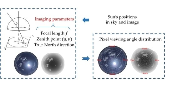
This study aims to estimate the geometric imaging parameters and achieve angular calibration for visible and infrared binocular all-sky-view cameras by using sun positions. The relationship between direct sunlight and projected sun pixel positions are regarded as the feature inputs to compute all parameters, such as zenith position, focal length, and rotation angle (hereafter with respect to the north). No extra calibration instruments are required. The only prior data we need to know are the precise location and projection model of the cameras; thus, the proposed method is quite flexible, and it addresses some difficulties in the angular calibration of visible and infrared binocular all-sky-view cameras to a certain extent. According to the obtained imaging parameters, the received visible and infrared radiation can be provided with geographic direction through a reprojection and back projection procedure (
Section 3.2), which is difficult to achieve with a traditional camera calibration based on calibration plates. Furthermore, the estimated geometric imaging parameters can be innovatively applied in the registration of visible and infrared clouds images pixel by pixel, enabling the possibility for further clouds information fusion.
The remainder of this paper is organized as follows. The visible and infrared binocular imaging system for ground-based clouds observation is presented and the data processing is also discussed in
Section 2. The method for the geometric imaging parameter estimation and the procedure for reprojection and back projection are detailed in
Section 3. The results of the geometric imaging parameter estimation and visible and infrared all-sky image registration are presented in
Section 4. Lastly, the conclusion drawn from the study is provided in
Section 5.
3. Materials and Methods
Angular calibration is the process of computing geometric imaging parameters, whereby the pixels on the image and their incident lights can correspond one-to-one. In this section, the method for estimating the geometric imaging parameters, such as the zenith point, the focal length, and the rotation angle with respect to the north, is presented in
Section 3.1. Then, the back projection process that determines the pixel-view-angle from any pixel positions and the reprojection process that determines the projected pixel coordinates from any incident lights are described in
Section 3.2.
3.1. Geometric Imaging Parameter Estimation
3.1.1. Projection Models of All-Sky-View Cameras
The linear projection model is the basic projection type of the pinhole cameras; however, a small FOV limits their application for all-sky observations. Accordingly, the visible and infrared all-sky-view cameras are often equipped with fisheye lenses to guarantee the capture of complete hemispherical sky images. In order to project as large a sky scene as possible into a limited image plane, the fisheye lens is usually designed to follow a certain projection model to map the incident light from the different zenith and azimuth angles to the image plane. The common projection models of the fisheye lens of all-sky-view cameras are the equidistant projection (1) and the equisolid angle projection (2) [
35], as follows:
where
denotes the zenith angle of incident light,
denotes the imaging radius from the zenith point, and
denotes the ratio of the imaging radius and the incident zenith angle, also called the focal length (pixels per degree).
The fisheye lenses of the visible and infrared binocular all-sky-view cameras of the ASC-200 instrument are designed to follow the equidistant projection; thus, we take the equidistant projection as an example in this study. Nevertheless, the proposed method is also suitable for other projection models, such as the abovementioned equisolid angle. In
Figure 3, we suppose a whole sky image
, in which
denotes the pixel coordinate of the
i-th row and
j-th column,
denotes the pixel coordinates of the zenith point
on the image, and
denotes the zenith angle of the incident light for pixel
. Thus, the projection function of the ASC-200 instrument can also be rewritten from Equation (1), as follows:
The unknown geometric imaging parameters, namely,
can be computed by solving Equation (3). Here, the decentering errors and high-order radial distortion are not considered in this equation because they are small in most lenses [
25].
3.1.2. Computing Zenith Point and Focal Length
To compute the zenith point
and focal length
, the sun’s pixel position
and the zenith angle of the corresponding direct sunlight
are used as inputs to solve Equation (3). Although three groups of ideal input data
are mathematically enough to solve unknowns
, and
, the sun’s pixel position
inevitably contains random errors introduced by the center detection of the Hough circle transformation. Accordingly, the Levenberg–Marquardt (LM) non-linear optimization algorithm is introduced, which takes a number of
data as inputs to minimize the error function described in (4), to decrease the effect of random errors and obtain the proper
and
values, as follows:
where
is the number of input data.
The LM algorithm is a typical optimization algorithm that combines the gradient descendent and Gauss–Newton methods and provides the solver for non-linear least squares minimization with fast convergence. Reasonable parameter initialization is an important premise for the success of the LM algorithm. The zenith point
values can be set as the center of all-sky images (i.e., half of the width and height of the images), because the zenith point is not as far from the center of the images. The focal length value can be estimated as the following Equation (5) by using edge pixel points in the effective area of all-sky images:
This notation is easily understandable because these edge points are far from the center at the distance of max imaging radius , and they are also the projection of incident light with max zenith angle .
After initialization, the LM algorithm takes groups of data as inputs, and further optimizes imaging parameters by iteratively minimizing the errors. The proper imaging parameters can be obtained until the errors are decreased to the fixed threshold we set, or the iteration numbers are up to the max value.
3.1.3. Computing Rotation Angle
In addition to the zenith point and focal length, the rotation angles of visible and infrared all-sky-view cameras can also be derived using the known azimuth angles and pixel coordinates of the sun. This feature is one of the advantages of stellar-based calibration, because traditional calibration methods based on calibration plates cannot obtain the geographical north direction. North on the image is the vector from the zenith point to the north direction. We take an infrared image as an example here. In
Figure 4, we set a reference vector
that is parallel to the
axis, and north must be deviated from reference vector
at a rotation angle set as
here [
36]. This study aims to compute the rotation angle
by using the sun’s positions.
We suppose the sun’s pixel point
with coordinates
on the image. The vector
is deviated from reference vector
at a rotation angle set as
here. The corresponding azimuth angle of the sun’s pixel point is already known as set
, which also means the angle between vector
and the north direction. Thus, the rotation angle
can be computed as follows:
where
is the number of input data. The angle
is computed using procedure (8), in which zenith point
is computed using the method in
Section 3.1.2, and the temporary variable
is defined as follows:
Thus, the visible and infrared binocular all-sky-view cameras can, respectively, obtain their rotation angles with respect to the north direction by using the azimuth angles and pixel coordinates of the sun, by which the rotation relation between these two binocular cameras can also be known.
3.2. Back Projection and Reprojection Process
The zenith and azimuth angles for every pixel on the captured all-sky images can be computed through a back projection process by using the geometric imaging parameters, namely,
, of visible and infrared all-sky-view cameras. According to Equation (3), the zenith angle of the received radiation for any corresponding pixel coordinate (
) can be computed as follows:
Meanwhile, the azimuth angle can be computed as , where the rotation angle is known, and the angle can also be computed through Equation (8). The zenith and azimuth angles are easily obtained for every pixel.
The projected pixel coordinates of the incident lights at any known zenith and azimuth angles can also be known by using the geometric imaging parameters
(i.e., the reprojection). Suppose that the zenith and azimuth angles of the incident light to be projected are
and
, respectively, its projected pixel coordinate (
) can be computed using the following Algorithm 1, where
is the distance between the projected pixel (
) and the zenith point (
), computed as product of the known focal length
and zenith angle
. Meanwhile,
is the angle deviated from the reference axis, computed as the sum of the known azimuth angle
and rotation angle
.
| Algorithm 1: Realization of the Re-projection Process |
| Input: zenith and azimuth angles , | 11: |
| Output: pixel coordinates , | 12: |
| /* are known constants here */ | 13: |
| 1: Set | 14: else if then |
| 2: Set | 15: |
| 3: if then | 16: |
| 4: | 17: |
| 5: end if | 18: else |
| 6: if then | 19: |
| 7: | 20: |
| 8: | 21: |
| 9: | 22: end if |
| 10: else if 90 then | 23: return , |
To date, the zenith and azimuth angles for every pixel on images and the projected pixel coordinates for any incident light can be easily calculated once the geometric imaging parameters are known, whether for visible or infrared all-sky-view cameras.
4. Experiment and Results
The angular calibration of visible and infrared binocular all-sky-view cameras using sun positions and their accuracy experiments are performed in this section. In
Section 4.1, the geometric imaging parameters of these two cameras are estimated using the proposed method. Various evaluation experiments are conducted to verify the accuracy of the obtained imaging parameters. First, the reprojection errors are computed and the comparison between the synthetic sun trajectory and the actual observed sun positions is performed in
Section 4.2. In addition, the zenith and azimuth angles back projected from the sun’s pixel positions are compared with the ground truth in
Section 4.3. Finally, the visible and infrared all-sky images captured using the ASC-200 instrument achieve registration at the pixel level by applying the estimated geometric imaging parameters in
Section 4.4.
4.1. The Geometric Imaging Parameter Estimation Results
To evaluate the effectiveness of the proposed method for simultaneously calibrating visible and infrared binocular all-sky-view cameras, the geometric imaging parameter estimation of the ASC-200 instrument is conducted. The zenith point
and focal length
for the infrared camera of ASC-200, as described in
Section 3.1.2, are determined by optimizing the initial values of Equation (4) using the LM algorithm, which takes the sun’s zenith angles and the corresponding pixel coordinates from the infrared training dataset as inputs. The iterative optimization achieves fast convergence within seconds because Equation (4) does not include the complex high-order terms. Thereafter, the rotation angle
is determined using the sun’s azimuth angles and the corresponding pixel coordinates from the infrared training dataset, as described in
Section 3.1.3. The same operations are also performed on the visible all-sky-view camera by using the visible training dataset.
The parameter estimation results are illustrated in
Table 1. The north direction is a ~25.45° anti-clockwise rotation from the reference axis in the visible all-sky-view camera, and a ~27.29° anti-clockwise rotation in the infrared all-sky-view camera. The difference in the rotation angles between these two binocular cameras is not so large, because they are manually adjusted to remain nearly aligned in the laboratory before the ASC-200 instrument is installed. Moreover, the estimation results of the other three imaging parameters are not far from their initial values. Thus, these obtained imaging parameters are basically in line with expectations.
4.2. Reprojection Analysis
4.2.1. Reprojection Errors
The reprojection errors for the visible and infrared all-sky-view cameras are performed to verify the accuracy of the estimated geometric imaging parameters. First, the re-projected pixel positions for the sun at the zenith and azimuth angles in the training dataset are calculated through estimated imaging parameters (
Section 3.2). Meanwhile, the corresponding pixel coordinates of the sun in the training dataset are treated as ground truth. Thus, the reprojection errors are the difference between the re-projected pixel positions and the ground truth (
Figure 5).
The reprojection errors are mostly within ±3.5 pixels in the visible all-sky-view camera, and they are more concentrated and mostly within ±1.5 pixels in the infrared all-sky-view camera. The main reason for that difference could be the uncertainty in detecting the sun’s center pixel because infrared images have smaller sun areas. Although the current mature calibration methods based on calibration plates for visible all-sky-view camera can achieve higher accuracy, the proposed method can still be considered satisfactory for meteorological observation in a more flexible way. The results prove the feasibility of the proposed method for simultaneously calibrating visible and infrared all-sky-view cameras.
4.2.2. Synthetic Sun Trajectory Calculation
The sun’s pixel coordinates on visible and infrared images can be computed at any time via the reprojection process by using the geometric imaging parameters of the visible and infrared all-sky-view cameras. The synthetic sun motion curve over a day is generated and visually compared with an actual observation to further verify the accuracy of the obtained geometric imaging parameters.
Instead of the training dataset, two days (2 and 13 August 2020) were selected to generate two synthetic sun trajectories here. First, the sun’s zenith and azimuth angles at every one second from 06:00 to 18:00 during each day were computed using the Reda and Andreas algorithm [
28]. Then, the sun’s pixel coordinates corresponding to the abovementioned zenith and azimuth angles were computed via reprojection using the obtained geometric imaging parameters. These re-projected sun pixel points over a day can form a synthetic sun motion curve on the images because the sun is moving continuously from east to west [
25]. Thus, two synthetic sun trajectories were generated for 2 and 13 August 2020.
To clearly present the difference between the synthetic sun trajectories and the observed sun positions, we plotted the synthetic sun curve into every image captured on those two days, and some results are presented in
Figure 6. The observed sun positions are basically on the plotted curves, proving the accuracy of two synthetic sun trajectories. This notation also indicates that the obtained imaging parameters are accurate, and that the proposed angular calibration method is effective for visible and infrared all-sky-view cameras.
4.3. Back Projection Errors
To further verify the accuracy of the proposed method, the back projection errors for visible and infrared all-sky-view cameras were computed using the estimated geometric imaging parameters. First, the zenith and azimuth angles back projected from the sun’s pixel coordinates in the validation dataset were calculated (
Section 3.2). Then, the corresponding zenith and azimuth angles of the sun in the validation dataset were treated as ground truth. The back projection errors are the difference between the calculated back projection results and the ground truth. The results of the back projection errors using all data from the validation dataset are shown in
Figure 7.
In the visible and infrared all-sky-view cameras the back projection errors of azimuth angles are mostly within ±0.25°, and those of the zenith angles are mostly within ±0.5°. We found that the fluctuations in the zenith and azimuth errors in the infrared camera are smaller than those in the visible camera. This finding is consistent with the results of the reprojection errors in which an infrared camera appears more concentrated, because the smaller sun area in the infrared sky images helps to decrease the uncertainty in the determination of the sun’s pixel points. The results are further analyzed in terms of the azimuth and zenith angles as follows.
In terms of the azimuth angles, the data of the visible camera are mostly scattered randomly near the zero line but show a higher deviation at noon. The main reason for this phenomenon is that the sun approaches the center of the images at that time, where a small pixel error is present but may cause a large azimuth deviation. In contrast, the data of the infrared camera are stable and almost concentrated on the zero line.
With regard to the zenith angles, the data of the visible camera are also randomly scattered near the zero line but show a higher deviation after 16:00. This phenomenon could be due to the sun approaching the edge of the images, where the radial distortion is more obvious and may not strictly obey the designed equidistant projection model. The data of the infrared camera from 9:00 to 10:00 and from 13:00 to 14:00 are missed because the sun was obscured by the clouds. The back projection results underestimate the zenith angles at the edge of images but overestimate them at the center of images. This situation might indicate that the infrared camera has a higher term distortion, and the errors might be lessened by adding three-order terms to the projection model in the future.
To analyze the back projection errors statistically, the Root Mean Square Error (RMSE), Normalized Mean Square Error (NRMSE), Mean Absolute Error (MAE), Normalized Mean Square Error (NMAE), and Standard Deviation (SD) are used, as follows:
where
denotes the estimated values;
denotes the ground truth;
and
are set as 360 and 0 for the azimuth angles, respectively; and
are set as 90 and 0 for the zenith angles, respectively.
The comparison results are shown in
Table 2. In the visible all-sky-view camera, the RMSE, MAE, and SD of the azimuth and zenith angles are approximately 0.2
. In the infrared all-sky-view camera, the RMSE, MAE, and SD of the azimuth angles are ~0.1
, and those of the zenith angles are ~0.25
. The NMAE and NRMSE are computed to compare the performance of the back projected zenith and azimuth angles whose value ranges are different, t. The results in
Table 2 show that the back projected zenith angles achieve NRMSE values of 0.297% and NMAE values of 0.239% for the visible all-sky-view camera, and NRMSE of 0.315% and NMAE of 0.284% for infrared all-sky-view camera, but the back projected azimuth angles have better performance.
4.4. Visible and Infrared Binocular Image Registration
The geometric imaging parameters of the visible and infrared cameras of the ASC-200 instrument have been estimated and proven to be accurate through the abovementioned experiments. Such a combined visible and infrared binocular imaging system provides complementary sky conditions through two different wavelength bands and has the potential for a wide variety of atmospheric studies. For instance, the system is helpful for ground-based cloud observation because the infrared all-sky-view camera is generally less affected by haze and aerosol but suffers from the missing observation of thin clouds. In contrast, the visible all-sky-view camera is capable of detecting thin clouds but fails to deal with haze and aerosol conditions. Thus, the registration of captured visible and infrared all-sky images provides more reliable cloud information. However, some difficulties in effectively matching visible and infrared clouds images still remain due to limitations in their discrepancies in imaging spectrum, FOV, and sensor resolutions, which also impedes further data comparison and fusion. Hence, in this subsection, we try to fill in the blanks and register visible and infrared all-sky images at the pixel level for the ASC-200 instrument by applying these estimated geometric imaging parameters.
Here, we mainly warp the visible images to match them with the infrared images because the infrared images have a smaller resolution. The matching processes can be simply divided into two steps. First, we calculate the zenith and azimuth angles of every pixel of the infrared images by back projection using the obtained geometric imaging parameters of the infrared camera. Then, the pixel points of the visible images corresponding to the calculated zenith and azimuth angles are selected by reprojection using the imaging parameters of the visible all-sky-view camera. Thus, these selected pixel points form a new visible all-sky image (i.e., the warped visible image, whose resolution is the same as the one of infrared image).
The warped visible images corresponded with the infrared images pixel by pixel, and some registration results are presented in
Figure 8. In comparison with the original visible all-sky images (
Figure 8a), the scene in the warped visible images is visually magnified because the FOV is narrowed during the registration. The horizontal (
Figure 8b) and vertical (
Figure 8c) comparison results indicated that the visible and infrared images matched well, except for the edge of the images. The results prove not only the feasibility of the proposed registration procedure but also the accuracy of the proposed angular calibration using sun positions.
In addition, some interesting cases also deserve to be discussed. In the second image of
Figure 8a, the visible all-sky image captures the long and thin contrail clouds. However, the infrared images almost miss that information. In the original visible image, we can know the existence of the contrail clouds; nevertheless, its warped visible image provides accurate pixel positions of the thin contrail clouds for the infrared image. In the third image of
Figure 8a, the visible image is slightly contaminated by aerosols, and the appearance becomes whiter. The clouds around sun area in the visible image can be clearly recognized and located through the corresponding infrared image. These results contribute to further ground-based cloud observation and analysis.
However, we also find that the warped visible image of low clouds, especially those that appear at the edges of the images, as shown in the fourth image of
Figure 8a, has some mismatch with the infrared images. This result could be because of the difference in the FOV between the visible and the infrared all-sky-view cameras. Although the visible and infrared binocular all-sky-view cameras are close to each other, the scene captured by the same zenith and azimuth angles still varies. The difference in the middle and high (altitude) clouds can be neglected. However, in the low clouds, the lower the clouds are, the larger the imaging difference is. The specific quantitative effects would be mathematically analyzed in the future, and the mismatch could be solved by introducing a non-rigid deformation.
5. Conclusions
Angular calibration is the import precondition for all-sky-view cameras to perform ground-based cloud observation and analysis. In this study, we have presented a convenient angular calibration method, which utilizes the sun’s positions to replace the traditional calibration plates to the obtain the zenith point and the focal length as well as the north direction, and successfully achieves simultaneous calibration for visible and infrared binocular all-sky-view cameras. The proposed method is flexible and simple because no extra calibration equipment is required. The only prior data needed are the camera location and the projection model. Accordingly, the zenith and azimuth angles for every pixel on the images, and the projected pixel points of incident radiation at any angle also can be recovered. The accuracy of the proposed method has been verified by the error estimation of reprojection and back projection. Moreover, the application of the proposed method, in effectively registering visible and infrared all-sky images at the pixel level, also verifies the performance of the proposed method.
This study is of great importance for further atmospheric research using visible and infrared all-sky-view cameras. After the angular calibration, the captured cloud images can be mapped onto the real geographical coordinates when cloud heights are known. The wind vector derived from the cloud motion of a sequence of images is also provided with the direction. Moreover, the visible and infrared registration could help promote a better understanding of the variation and interaction among clouds–aerosols–radiation and contribute to the related research on climate change through multi-channel imaging features. In our next work, the registration results for low clouds need to be further optimized and the registered visible and infrared clouds images will be fused to improve the ground-based cloud observation.


