Article

Analysis of BDS/GPS Signals’ Characteristics and Navigation Accuracy for a Geostationary Satellite

1
School of Information and Electronics, Beijing Institute of Technology, No. 5 South Street, Zhongguancun, Haidian District, Beijing 100081, China
2
Department of Navigation, Beijing Institute of Satellite Information Engineering (Aerospace Star Technology Co., Ltd), 77 Jindai Road, Zhongguancun, Haidian District, Beijing 100095, China
3
School of Geodesy and Geomatics, Wuhan University, Wuhan 430079, China
*
Author to whom correspondence should be addressed.
Remote Sens. 2021, 13(10), 1967; https://doi.org/10.3390/rs13101967
Submission received: 11 April 2021 / Revised: 11 May 2021 / Accepted: 14 May 2021 / Published: 18 May 2021

Abstract

:
The utilization of Global Navigation Satellite System (GNSS) is becoming an attractive navigation approach for geostationary orbit (GEO) satellites. A high-sensitivity receiver compatible with Global Position System (GPS) developed by the United States and BeiDou Navigation Satellite System (BDS) developed by China has been used in a GEO satellite named TJS-5 to demonstrate feasibility of real-time navigation. According to inflight data, the GNSS signal characteristics including availability, position dilution of precision (PDOP), carrier-to-noise ratio (C/N0), observations quantity and accuracy are analyzed. The mean number of GPS and GPS + BDS satellites tracked are 7.4 and 11.7 and the mean PDOP of GPS and GPS + BDS are 10.24 and 3.91, respectively. The use of BDS significantly increases the number of available navigation satellites and improves the PDOP. The number of observations with respect to C/N0 is illustrated in detail. The standard deviation of the pseudorange noises are less than 4 m, and the corresponding carrier phase noises are mostly less than 8 mm. We present the navigation performance using only GPS observations and GPS + BDS observations combination at different weights through comparisons with the precision reference orbits. When GPS combined with BDS observations, the root mean square (RMS) of the single-epoch least square position accuracy can improve from 32.1 m to 16.5 m and the corresponding velocity accuracy can improve from 0.238 m/s to 0.165 m/s. The RMS of real-time orbit determination position accuracy is 5.55 m and the corresponding velocity accuracy is 0.697 mm/s when using GPS and BDS combinations. Especially, the position accuracy in x-axis direction reduced from 7.24 m to 4.09 m when combined GPS with BDS observations.

Graphical Abstract

1. Introduction

Nowadays, real-time orbit determination based on GNSS is successfully used for GEO satellites which traditionally depended on ground-based ranging systems. Because of the advantages of cost-effectiveness and autonomy, the utilization of GNSS receivers in GEO missions has become an attractive alternative for orbit determination and timing. In the 1980s, the concept of using GPS on GEO satellite has been introduced. In 2000, the United States released the operational requirements document (ORD) and presented the first description of space service volume (SSV), which was a shell extending from 3000 km altitude to approximately the GEO altitude, or 36,000 km [1,2]. In 2006, Bauer formally described the concept of SSV, and made it clear that SSV coverage characteristic with the GPS constellation [2]. Recently, considerable effort has been exerted by the United Nations-sponsored International Committee on GNSS (ICG) to expand the GNSS use into the SSV, by conducting initiatives to ensure GNSS signals available in the SSV. ICG is leading to coordinate the development of an interoperable SSV across the navigation service provider, including GPS, BDS, Galileo, GLONASS, etc. [3,4]. An analysis of the BDS-3 performance of the main-lobe and the side-lobe signals for three typical SSV missions is conducted based on antenna patterns from the actual mission design data [5,6].
However, the use of GNSS signals for SSV users has special challenges. Several researches have carried out studies in signal link budgets and performance for SSV applications. In GEO missions, the altitude of GNSS receiver is higher than that of the navigation satellite constellation and the geometric distribution of the navigation satellite is poor. Most of the signals from the main lobe of the GNSS transmitting antenna are blocked by the earth [7,8,9]. It is necessary to receive the side lobe signals to increase the number of available navigation satellites and improve the geometric distribution [9]. Because the power of side-lobe signals are generally about 20 dB lower than that of the main-lobe ones, we need to improve sensitivity of the receiver to process these signals [10,11,12]. In spite of these difficulties, several feasibility studies for orbit determination with GNSS in GEO missions have been presented. A software simulation was made to assess the performance of autonomous orbit determination using GPS and Galileo signals. The accuracy of GEO orbit determination in this simulation was less than 100 m [13]. An iterative Kalman filter based on nonlinear dynamic model was used with GPS measurements for GEO spacecraft navigation. The tests of this filter were conducted with a GPS signal simulator and a dual-star single-frequency receiver [14]. Comprehensive simulation results and analysis show that using GPS and Galileo navigation for GEO orbits has operational benefits, even current space borne state-of-the-art receivers are considered [15]. A system-level performance and qualification test for GEO missions has been conducted using a space borne GPS receiver, named General Dynamics’ Viceroy-4. It has demonstrated the ability to provide 100% position, velocity, and time data by acquiring and tracking a significant number of side lobe signals [11]. GNSS signal characteristics in GEO, taking into consideration the L1 and L5 frequency bands and the GPS and Galileo constellations, are specifically investigated. Simulation tests and experiments using a high sensitivity commercial off-the-shelf (COTS) receiver were presented to validate the navigation performance [16].
Moreover, several missions have demonstrated the flight performance of GNSS signal processing and onboard orbit determination in GEO orbit. In Europe, Galileo navigation satellite GIOVE-A with a SGR-GEO receiver and an experimental results show that weak side lobe signals have been acquired and tracked by this receiver to increase the number of available satellites in medium-earth-orbit (MEO) and GEO. The position accuracy in this experiment was less than 100 m [17,18]. The Geostationary Operational Environmental Satellite-R (GOES-R) adopts Viceroy-4 as an onboard GPS receiver to provide orbit determination data for guidance, navigation, and control systems [19]. According to on-orbit performance, the position accuracy is less than 15.2 m and the velocity accuracy is less than 0.52 cm/s [20]. In Europe, a receiver Mosaic GNSS has been adopted in SmallGEO platform used in the Hispasat 36W-1 mission. The flight results show that signals with C/N0 at 27dB-Hz–28 dB-Hz are received and the RMS of position error is around 120 m [21]. In a GEO mission of TJS-2, the onboard receiver can track 6–8 GPS satellites and the minimum C/N0 of signals tracked was 24 dB-Hz. The RMS of position error between 30 h orbit determination arcs is 2.14 m using the overlap comparisons assessment [22]. Furthermore, several publications have addressed the feasibility of GNSS-based navigation for lunar missions. Navigation results obtained with a realistic simulator were presented by the past studies to demonstrate the feasibility of lunar orbit spacecraft applications that rely on GNSS receivers [23,24].
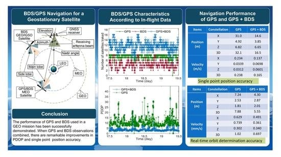
The GEO satellite of No.5 Telecommunication Technology Test Satellite (TJS-5) was launched on 7 January 2020, and a high sensitivity GNSS receiver has been installed to realize tracking GPS and BDS signals and to perform orbit determination autonomously. In this study, we investigate the flight signal characteristics in this GEO missions, considering GPS and BDS in terms of availability, PDOP, C/N0, the observation quantity and accuracy. Then, we give the performance evaluation of single-epoch least square solutions and real–time orbit determination solutions and discuss the contribution of BDS signals to GEO applications.

2. System and Methods Description

In the GEO satellite of TJS-5 experiment, the altitude of the receiver is higher than that of the MEO navigation satellite, as shown in Figure 1. Therefore the GNSS receiver receives the signals from the other side of the earth and the elevation of this receiver is negative. A high-gain antenna in form of bifilar helix mounted in a deployable structure is oriented toward the center of the earth. The gain of this antenna is more than 7 dB within an angle of −30°–+30° according to the measured data. It should be noted that the BDS GEO/IGSO satellites and receiver are on the same orbital plane over the Asia Pacific. The elevation of these BDS GEO/IGSO satellites is beyond the beam range of the receiving antenna (−30°–+30°). In this situation, whether BDS GEO/IGSO satellites signal can be received or not depends on the signal transmission distance, the side-lobe gain of the navigation satellite antenna and the receiving antenna gain.
A high-sensitivity receiver are used for acquisition and tracking the weak navigation signals in this experiment. Table 1 provides some information about this GNSS receiver. The architecture of this high-sensitivity spaceborne receiver is shown in Figure 2. The filter, low noise amplifier (LNA), and the RF-front ends downconvert the navigation signals to intermediate frequency (IF) signals which are sampled at 56.8 MHz. The RF-front is driven by a stable, low-phase noise, 10MHz oven-controlled crystal oscillator (OXCO). The high sensitivity fast acquisition and tracking are performed in the digital application specific integrated circuit (ASIC), which is embedded in a rad-hard system on chip (SOC). Raw measurements (pseudorange, carrier phase, ephemeris, time, etc.) are generated and used for the single point position and real-time orbit determination by the CPU in this SOC. The receiver can track up to eight GPS satellites and eight BDS satellites with 16-channel hardware correlators simultaneously. A real-time orbit determination filter based on an extended Kalman filter (EKF) in this receiver works with pseudorange observations and dynamic models.
This receiver can process L1 C/A signals of 32 GPS satellites of the PRN G01–G32. Moreover, this receiver can be compatible with the BeiDou regional system (BDS-2) and the BeiDou global system (BDS-3), which have three orbit types: medium earth orbit (MEO), inclined geostationary orbit (IGSO), and GEO [25,26]. The receiver can process the B1I signals of 37 BDS satellites of the PRN C01–C37. Because C15, C17, C18 and C31 satellites are out of service, there are 33 BDS satellites which can be tracked by the receiver, including 5 BDS-2 GEO, 7 BDS-2 IGSO, 3 BDS-2 MEO, and 18 BDS-3 MEO satellites, as listed in Table 2.

3. BDS/GPS Signal Characteristics

The onboard receiver has demonstrated the ability of tracking GPS and BDS signals in GEO. The flight data generated by the GNSS receiver was downloaded to the ground. In this section, we analyze the signal characteristics of BDS and GPS including observations quantity and distribution, availability, PDOP, observations accuracy.

3.1. Observations Quantity and Availability

In two days from 12:00 on 17 May to 12:00 on 19 May 2020, a total of 512,819 GPS observations and 299,523 BDS observations have been obtained at 2 s intervals. The number of GPS satellites tracked includes: 12 IIF, 11 IIR, 7 IIR-M, and 2 III satellites. The percentage of the GPS observations for IIF, IIR, IR-M, III satellites, are counted to be 27.4%, 41.4%, 27.6%, and 3.6%, respectively. The average observations of GPS III and IIF satellites are significantly less than those of the other two types of GPS satellites.
Among the 33 BDS satellites, only C01, C02 and C05 of 3 BDS GEO satellites have no observations data. The percentage of the observations from 2 BDS GEO (C03 and C04), 7 BDS IGSO, and 21 BDS MEO satellites, are counted to be 21.7%, 9.1%, 69.2%, respectively. Although the number of BDS GEO satellites tracked is only two, the observations quantity of these two satellites accounts for a large proportion.
According to results shown in Figure 3, the mean number of the GPS satellites tracked over two days is 7.4 and the mean number for the BDS satellites tracked is 4.3. Because each constellation in the receiver has only eight-channel hardware correlator, it can track up to eight satellites simultaneously. Considering the combination of GPS and BDS constellations, it remarkably increases the number of satellites tracked. The mean number for the GPS + BDS satellites tracked is 11.7. Figure 4 gives the tracking periods of the BDS satellites over two days. The BDS satellite of GEO C04 has the longest continuous tracking time, accounting for 68.9% of the two days. The continuous tracking time of the six BDS IGSO satellites is shorter than other GPS or BDS satellites.

3.2. PDOP

PDOP in common use is useful to characterize the accuracy of the position and velocity solutions. It can be computed based on the square root of the trace of the ( H T H ) 1 matrix. The matrix H is called as the design matrix or the Jacobian matrix and related with the least-squares solution in single point position. The matrix of H is expressed in form [27,28]
H = [ a x i 1 a y i 1 a z i 1 1 0 a x i 2 a y i 2 a z i 2 1 0 a x i n a y i n a z i n 1 0 a x j 1 a y j 1 a z j 1 1 1 a x j 2 a y j 2 a z j 2 1 1 a x j m a y j m a z j m 1 1 ]
where n, m are the number of GPS or BDS satellites, respectively. a x i n , a y i n , a z i n denote the direction cosine vector from the receiver position of x , y , z to the nth satellite of GPS. a x j m , a y j m , a z j m denote the direction cosine vector from the receiver position of x , y , z to the mth satellite of BDS. When using combination of GPS and BDS, the matrix H is a (n + m) × 5, otherwise the matrix H is a n × 4 and the last column in Equation (1) is ignored [27,28]. The PDOP can be obtained from
P D O P = ( H T H ) 1 , 1 1 + ( H T H ) 2 , 2 1 + ( H T H ) 3 , 3 1
According to the Equation (1) and Equation (2), the mean value of PDOP of GPS and GPS + BDS over two days are 10.24 and 3.91, respectively. It can obviously reduce the PDOP when we use GPS + BDS constellations, as shown in Figure 5.
Sky views of the GPS and BDS satellites tracked are given in Figure 6. The nadir angles range of BDS satellites tracked is larger than that of GPS satellites tracked. Especially, the nadir angles of BDS GEO and IGSO satellites tracked are in range of 45° to 85°, which are larger than those of BDS MEO satellites tracked. This indicates that a positive contribution of BDS GEO and IGSO satellites to the improvement of PDOP is expected, although the number of these satellites tracked is not large in this mission.

3.3. Observations Distribution and Accuracy

C/N0 is an important indicator about the signals power, which is related to the accuracy of observations. Figure 7 gives the distribution of GPS and BDS observations with respect to C/N0. Most of the GPS, BDS-2 IGSO, and BDS-2 MEO observations are in C/N0 range of above 30 dB-Hz and below 35 dB-Hz. However, for BDS-3 MEO satellites, the number of observations in C/N0 above 40 is more than that in other C/N0 range. This indicates that most of the observations was observed from the main-lobe signals of BDS-3 MEO antenna.
The pseudorange P u i and carrier phase L u i , respectively, are [22]
{ P u i = ρ + c δ t u c δ t s + δ ρ t r o p + δ ρ i o n o + ε p i L u i = ρ + c δ t u c δ t s + δ ρ t r o p δ ρ i o n o + λ N u i + ε L i
where ρ is the geometric range between the receiver and the navigation satellite; δ t s and δ t u are navigation satellite clock offset and receiver clock offset, respectively; and c is the speed of light. δ ρ t r o p   and   δ ρ i o n o represent the troposphere and ionosphere delay errors, respectively. The parameter λ N u i denotes the ambiguity of the carrier phase measurements. ε p i and ε L i are the measurement noises, for the pseudorange and the carrier phase, respectively. We use epoch difference arithmetics to analyze carrier phase measurement noise [22,29]. In general, only random noise remains when using triple difference, which is described as follows:
ε P = P u i P u i 1 ( P u i 1 P u i 2 ) ( P u i 1 P u i 2 P u i 2 + P u i 3 ) = P u i 3 P u i 1 + 3 P u i 2 P u i 3
ε L = L u i L u i 1 ( L u i 1 L u i 2 ) ( L u i 1 L u i 2 L u i 2 + L u i 3 ) = L u i 3 L u i 1 + 3 L u i 2 L u i 3
Therefore, we use Δ ε p / 2 and ε L / 20 as the pseudorange and carrier phase noise statistics. The standard deviation of the pseudorange and carrier phase noises are shown in Figure 8. The pseudorange measurement noises are less than 4 m, and the carrier measurement noises are mostly less than 8 mm. The pseudorange and carrier phase noises of BDS measurements are lower than those of GPS measurements. Especially the pseudorange noises of BDS measurements are mostly less than 2 m in term of C/N0 bellow 30, which are obvious lower than those of GPS measurements. According to accuracy estimation method of the code tracking errors as described in [27], the thermal noise jitter of code delay locked loop (DLL) is related to code chipping rate. Therefore, the pseudorange accuracy of BDS measurements is higher than that of GPS measurements, because the BDS B1I code chipping rate of 2046 Kbps is higher than the GPS C/A code chipping rate of 1023 Kbps.

4. Navigation Performance

In this section, the accuracy of single point position solutions and real-time orbit determination solutions are analyzed over two days from 9:00 on 17 May to 9:00 on 19 May 2020. No truth orbits are available as references in evaluating navigation accuracy. However, we use the precision orbit determination solutions generated on ground, which are estimated about submeter level through assessment of overlap comparisons proposed in [22].

4.1. Single-Point Position Accuracy

The single-epoch least square solutions are recalculated at 20 s intervals using flight observations and broadcast ephemerides. Comparisons between the solutions using only GPS observations and GPS + BDS observations combination at weights of 1:2, 1:1, 2:1, 4:1 and the precision orbit determination solutions are reported in Table 3. The accuracy of these solutions is related to measurement errors and the PDOP. Because the PDOP of the combined GPS+BDS satellites improves (see in Section 3.2), remarkable improvements in position and velocity accuracy are made with the combined GPS and BDS observations. When GPS observations combined with BDS observations at the weight of 1:1, the RMS of the position accuracy can improve from 32.1 m to 16.5 m and the corresponding velocity accuracy can improve from 0.238 m/s to 0.165 m/s. When BDS observations are involved, the accuracy of position and velocity in the x-axis direction is improved obviously. The x-axis direction is basically consistent with the radial direction of the orbit of the receiver, according to the location of the receiver. The position error in radial direction will be significantly higher than that in the other two directions, because there is a weak constraint in this direction [22]. According to the results in Table 3, except that the velocity differences is larger than others at weight coefficients 1:2, there is no big difference on the navigation accuracy with four different weight coefficients.
In order to evaluate the improvement obtained with BDS MEO or BDS GEO/IGSO satellites, we use GPS + BDS MEO and GPS + BDS GEO/IGSO observations combinations to calculate single-epoch least square solutions respectively. When we use GPS + BDS pseudorange combinations, one more unknown parameter (BDS clock offset) becomes available. At least two BDS satellites pseudorange combinations should be used to make sense of the BDS pseudorange contribution to the solutions. Therefore, one set of position and velocity solutions using GPS + BDS GEO/IGSO combinations are calculated when the number of BDS GEO and IGSO satellites tracked is more than or equal to two. Another set of solutions are also given using only GPS pseudorange with the same epoch as the previous set. Comparing the two sets of solutions with the reference of the precision orbit determination solutions, the position and velocity differences are reported in Table 4. In this case, using additional BDS GEO and IGSO observations reduces the position error from 28.9 m to 15.9 m and the velocity error from 0.218 m/s to 0.184 m/s.
We use the same method to give the solutions using GPS + BDS MEO observations combinations and only GPS observations. We compare these solutions with the reference of the precision orbit determination solutions, as shown in Table 5. When using additional BDS MEO observations, the accuracy improvement in position is small and the accuracy improvement in velocity is even worse. It is further confirmed that the improvement of the position and velocity accuracy comes from combinations with BDS GEO and IGSO.

4.2. Real-Time Orbit Determination Accuracy

In order to improve the navigation accuracy, a real-time orbit determination filter based on an extended Kalman filter (EKF) was used with GNSS pseudorange observations and dynamic models. In the absence of observations, continuous navigation results can be calculated through orbit propagation.

4.2.1. Processing Model and Strategy

The equation of the motion of a GEO satellite can be expressed as [30]:
r ˙ = v v ˙ = a m ( r , v , t ) + w ( t )
where r , v , and t are the position, velocity and time of the GEO satellite in a geocentric inertial coordinate frame, respectively. a m is the total gravity, perturbing acceleration, including the nonspherical part of the gravitational attraction of the Earth, lunisolar gravitational perturbations, solar radiation pressure, and earth tide. w ( t ) is the empirical acceleration and can expressed in radial, along-track, and cross-track, which account for unmodeled forces. Various simplifications to the force models used in this filter are shown in Table 6, according to the reference in [31,32]. Atmospheric drag, troposphere and ionosphere delay are ignored. In this mission, we adopt the 50 × 50 order of gravity model in order to satisfy the GTO scenario of which perigee altitude is close to LEO.
The state equation of EKF can be propagated by a fourth-order fixed step Runge-Kutta integrator of the adopted equation of the motion within the time update step. The filter state vector is expressed as following [30]:
X k 1 = [ x ,   y ,   z ,   x ˙ ,   y ˙ ,   z ˙ ,   b G ,   b B ,   b ˙ u ,   C R ,   w R ,   w A ,   w C ] T
where ( x ,   y ,   z ) is position vector and ( x ˙ ,   y ˙ ,   z ˙ ) is the velocity vector, respectively. b G is GPS clock offset, b B is BDS clock offset, b ˙ u is clock drift of the receiver, and C R is the state of solar radiation pressure parameter. ( w R ,   w A ,   w C ) represents the vector of empirical accelerations in radial (R), along-track (A), and cross-track (C), respectively, which are modeled by three first-order Gauss–Markov processes to account for the unmodeled forces [33].
The observation equation of EKF can be expressed as following:
P K = H k ( X k X ^ k ) + V k
where P K is pseudorange measurement of the ith navigation satellite. V k is measurement noise. The measurement matrix of H k is calculated from the linearization estimation of the pseudorange observation equation, as introduced in [34], which can be described in the following:
H k = [ x ^ k x i s ρ i ,   y ^ k y i s ρ i , z ^ k z i s ρ i , 0 1 × 3 , T 1 × 3 , 0 , 0 1 × 3 ]
where ( x i s ,   y i s ,   z i s ) indicates the position of the ith navigation satellite, ( x ^ k , y ^ k , z ^ k ) is the position from predicted estimate state vector X ^ k . T 1 × 3 sets [ 1 , 0 , 0 ] for GPS or [ 0 , 1 , 0 ] for BDS.

4.2.2. Analysis Results

The navigation solutions are generated by a real-time orbit determination software using flight GNSS observations and broadcast ephemerides. Orbit determination filter based on EKF updates with observations at step size of 20 s. The RMS differences of position and velocity between real-time orbit determination solutions with different pseudorange combination weights and the reference of the precision orbit determination solutions as listed in Table 7. According to the 3D results, the highest position and velocity accuracy are given at the weight of 1:1. In that case, the RMS of position differences is 5.55 m and that of position differences is 0.697 mm/s. With the increase of the weight of BDS observations, although the accuracy in x-axis direction has some improvements, the accuracy in y-axis direction and z-axis direction become worse. For instance, when GPS and BDS pseudorange combined at a weight of 1:2, the RMS of position differences in x-axis direction reduce from 7.24 m to 4.09 m. However, the corresponding differences in y-axis and z-axis direction increase by 1.06 m to 0.37 m. In detail, we give the position differences between real-time orbit determination solutions using GPS + BDS observations combinations at a weight of 1:1 and only GPS observations, and the reference of the precision orbit determination solutions, as shown in Figure 9.

5. Conclusions

For the GEO satellite of the TJS-5 mission, we use a high sensitivity receiver with a high-gain antenna to realize real-time navigation. In this study, we analyze the inflight data generated by this sensitivity receiver, which can track weak BDS and GPS signals. We investigate the GNSS signal characteristics, including observations quantity and distribution, availability, PDOP, observations accuracy. It is found that when BDS and GPS are combined, the number of navigation satellites tracked will increase significantly and the PDOP can be reduced obviously. Although the number of BDS satellites tracked is less than that of GPS, it makes a positive contribution to the improvement of PDOP and navigation solutions. In order to analyze the observations distribution characteristics, the number of observations with respect to the C/N0 was analyzed. Most of the GPS and BDS observations are concentrated in C/N0 range of above 30 dB-Hz and below 35 dB-Hz, except BDS-3 MEO satellite observations. We use epoch difference arithmetics to analyze observations noises. The standard deviation of the pseudorange noises are less than 4 m, and the corresponding carrier phase noises are mostly less than 8 mm. The pseudorange and carrier phase noises of BDS measurements are lower than those of GPS measurements.
We give the navigation performance using only GPS observations and GPS + BDS observations combination at different weights. As for the single-epoch least square solutions, remarkable improvements in position and velocity accuracy are made with the combined GPS and BDS observations. Through comparisons with the precision reference orbits, when combining GPS observations with BDS observations at the weight of 1:1, the RMS of these position solutions accuracy can improve from 32.1 m to 16.5 m and the corresponding velocity accuracy can improve from 0.238 m/s to 0.165 m/s. Especially in x-axis direction, the position accuracy can improve from 31.0 m to14.6 m. We discuss the accuracy influence when BDS GEO/IGSO and MEO combined with GPS respectively. In this case, when BDS IGSO and GEO observations involved, there is an obvious improvement in position and velocity. As for the real-time orbit determination solutions, the RMS of position accuracy is 5.55 m and that of velocity accuracy is 0.697 mm/s when GPS and BDS pseudorange combined at a weight of 1:1. When we increase the weight of BDS observations, although the accuracy in x-axis direction has some improvements, the accuracy in y-axis direction and z-axis direction become worse.
We need to do further research into some aspects to improve the accuracy in future high-earth-orbit missions. A comprehensive utilization of GPS, GLONASS, BDS and GALILEO system should be taken into account to improve orbit determination accuracy by increasing the number of available satellites and reducing PDOP. In addition, carrier observations should be considered to increase navigation accuracy, because the accuracy of carrier observations is higher than that of pseudorange observations. For the high-orbit satellites with orbit maneuver, the research on how to use IMU to realize integrated navigation is necessary.

Author Contributions

Conceptualization, M.W.; methodology, M.W. and T.S.; software, M.W. and W.Z.; validation, M.W. and T.S.; formal analysis, M.W. and H.H.; investigation, M.W. and W.Z.; resources, M.W.; data curation, M.W.; writing—original draft preparation, M.W. and T.S.; writ-ing—review and editing, M.W.; visualization, M.W.; supervision, H.H.; project administration, H.H.; funding acquisition, W.Z. All authors have read and agreed to the published version of the manuscript.

Funding

This work was supported by the National Natural Science Foundation of China (NSFC) under Grant Nos. 62073044.

Data Availability Statement

The data that support the findings of this study are available from the corresponding author upon reasonable request.

Acknowledgments

The authors would like to acknowledge the IGS for providing the broadcast ephemeris and GNSS Research Center of Wuhan University providing precision orbit determination solutions.

Conflicts of Interest

The authors declare no conflict of interest.

References

  1. Jorgensen, P. Autonomous navigation of geosynchronous satellites using the NAVSTAR global positioning system. In Proceedings of the National Telesystems Conference, Galveston, TX, USA, 1–7 December 1982. [Google Scholar]
  2. Bauer, F.H.; Moreau, M.C.; Dahle-Melsaether, M.E.; Petrofski, W.P.; Stanton, B.J.; Thomason, S.; Harris, G.A.; Sena, R.P.; Parker, L. The GPS space service volume. In Proceedings of the 19th International Technical Meeting of the Satellite Division of The Institute of Navigation (ION GNSS 2006), Fort Worth, TX, USA, 26–29 September 2006. [Google Scholar]
  3. Bauer, F.H.; Parker, J.J.K.; Welch, B.; Enderle, W. Developing a robust, interoperable GNSS space service volume (SSV) for the global space user community. In Proceedings of the ION ITM 2017, Monterey, CA, USA, 30 January–2 February 2017; pp. 132–149. [Google Scholar]
  4. Parker, J.J.K.; Bauer, F.H.; Ashman, B.W.; Miller, J.J.; Enderle, W.; Blonski, D. Development of an Interoperable GNSS Space Service Volume. In Proceedings of the 31st International Technical Meeting of the Satellite Division of the Institute of Navigation (ION GNSS+ 2018), Miami, FL, USA, 24–28 September 2018; pp. 1246–1256. [Google Scholar] [CrossRef] [Green Version]
  5. Lin, K.; Zhan, X.Q.; Yang, R.; Shao, F.W.; Huang, J.H. BDS Space Service Volume characterizations considering side-lobe signals and 3D antenna pattern. Aerosp. Sci. Technol. 2020, 106, 106071. [Google Scholar] [CrossRef]
  6. Shuai, J.; Zhan, X.Q.; Lu, J.; Feng, S.J.; Ochieng, W.Y. Characterisation of GNSS Space Service Volume. J. Navig. 2015, 68, 107–125. [Google Scholar]
  7. Ruiz, J.L.; Frey, C.H. Geosynchronous Satellite Use of GPS. In Proceedings of the 18th International Technical Meeting of The Satellite Division of the Institute of Navigation (ION GNSS 2005), Long Beach, CA, USA, 13–16 September 2005; pp. 1227–1232. [Google Scholar]
  8. Force, D.A.; Miller, J.J. Combined Global Navigation Satellite Systems in the Space Service Volume. In Proceedings of the International Technical Meeting 2013, San Diego, CA, USA, 27–29 January 2013. [Google Scholar]
  9. Rathinam, A.; Dempster, A.G. Effective utilization of space service volume through combined GNSS. In Proceedings of the 29th International Technical Meeting of the Satellite Division of the Institute of Navigation (ION GNSS+ 2016), Portland, OR, USA, 12–16 September 2016. [Google Scholar]
  10. Parker, J.; Valdez, J.; Bauer, F.; Moreau, M. Use and protection of GPS side lobe signals for enhanced navigation performance in high Earth orbit. In Proceedings of the 39th Annual American-Astronautical-Society Rocky Mountain Section Guidance, Navigation and Control Conference, Breckenridge, CO, USA, 5–10 February 2016; pp. 329–341. [Google Scholar]
  11. King, M. Extending the use of GPS to geostationary altitudes. In Proceedings of the AIAA SPACE 2011 Conference & Exposition, Long Beach, CA, USA, 27–29 September 2011; pp. 1–9. [Google Scholar] [CrossRef]
  12. Czopek, F.M. Description and Performance of the GPS Block I and II L-Band Antenna and Link Budget. In Proceedings of the 6th International Technical Meeting of the Satellite Division of The Institute of Navigation (ION GPS 1993), Salt Lake City, UT, USA, 22–24 September 1993; pp. 37–43. [Google Scholar]
  13. Lorga, J.M.; Silva, P.F.; Cintio, D.A.; Dovis, F.; Kowaltschek, S.; Jimenez, D.; Jansson, R. GNSS sensor for autonomous orbit determination. In Proceedings of the 23rd International Technical Meeting of the Satellite Division of the Institute of Navigation, Portland, OR, USA, 21–24 September 2010; pp. 2717–2731. [Google Scholar]
  14. Mikhaylov, N.V.; Koshaev, D.A. Navigation solution for a geostationary satellite based on its dynamic equations and occasional gnss measurements. Gyroscopy Navig. 2015, 6, 87–100. [Google Scholar] [CrossRef]
  15. Marmet, F.X.; Maureau, J.; Calaprice, M. GPS/Galileo navigation in GTO/GEO orbit. Acta Astronaut. 2015, 117, 263–276. [Google Scholar] [CrossRef]
  16. Capuano, V.; Shehaj, E.; Blunt, P.; Botteron, C.; Farine, P.A. High accuracy GNSS based navigation in GEO. Acta Astronaut. 2017, 136, 332–341. [Google Scholar] [CrossRef]
  17. Ebinuma, T.; Unwin, M. GPS receiver demonstration on a Galileo test bed satellite. Navigation 2007, 60, 349–362. [Google Scholar] [CrossRef]
  18. Unwin, M.; Steenwijk, R.D.V.V.; Blunt, P.; Hashida, Y.; Kowaltschek, S.; Price, S.R. Navigating Above the GPS Constellation-Preliminary Results from the SGR-GEO on GIOVE-A. In Proceedings of the 26th International Technical Meeting of The Satellite Division of the Institute of Navigation (ION GNSS+ 2013), Nashville, TN, USA, 16–20 September 2013; pp. 3305–3315. [Google Scholar]
  19. Chapel, J.; Stancliffe, D.; Bevacqua, T.; Winkler, S.; Clapp, B.; Rood, T. Guidance, navigation, and control performance for the goes-r spacecraft. Ceas Space J. 2015, 7, 87–104. [Google Scholar] [CrossRef] [Green Version]
  20. Winkler, S.; Ramsey, G.; Frey, C.; Chapel, J.; Chu, D.; Freesland, D.; Krimchansky, A.; Concha, M. GPS receiver on-orbit performance for the GOES-R spacecraft. In Proceedings of the 10th International ESA Conference on GNC Systems, Salzburg, Austria, 29 May–2 June 2017. [Google Scholar]
  21. Neumann, N.; Dd Bruijn, F.; Lübke-ossenbeck, B.; Marx, M.; Gottzein, E.; Dauphin, H.; Chamarro, M.S. In-flight results from the GPS receiver on Small GEO. In Proceedings of the 68th International Astronautical Congress, Adelaide, Australia, 25–29 September 2017. [Google Scholar]
  22. Jiang, K.; Li, M.; Wang, M.; Zhao, Q.; Li, W. TJS-2 geostationary satellite orbit determination using onboard GPS measurements. GPS Solut. 2018, 22, 87. [Google Scholar] [CrossRef]
  23. Capuano, V.; Blunt, P.; Botteron, C.; Tian, J.; Leclère, J.; Wang, Y.G.; Basile, F.; Farine, P. Standalone GPS L1 C/A receiver for lunar missions. Sensors 2016, 16, 347. [Google Scholar] [CrossRef] [Green Version]
  24. Manzano-Jurado, M.; Alegre-Rubio, J.; Pellacani, A.; Seco-Granados, G.; López-Salcedo, J.A.; Guerrero, E.; García-Rodríguez, A. Use of weak GNSS signals in a mission to the moon. In Proceedings of the 7th ESA Workshop on Satellite Navigation Technologies and European Workshop on GNSS Signals and Signal Processing (NAVITEC), Noordwijk, The Netherlands, 3–5 December 2014; pp. 1–8. [Google Scholar] [CrossRef]
  25. Li, M.; Yuan, Y. Estimation and Analysis of BDS2 and BDS3 Differential Code Biases and Global Ionospheric Maps Using BDS Observations. Remote Sens. 2021, 13, 370. [Google Scholar] [CrossRef]
  26. Hein, G.W. Status, perspectives and trends of satellite navigation. Sat. Navig. 2020, 1, 22. [Google Scholar] [CrossRef]
  27. Kaplan, E.D.; Hegarty, C.J. Understanding GPS: Principles and Applications, 2nd ed.; Artech House Inc.: Boston, MA, USA, 2005. [Google Scholar]
  28. Teng, Y.; Wang, J.; Qi, H. Minimum of Geometric Dilution of Precision (GDOP) for five satellites with dual-GNSS constellations. Adv. Space Res. 2015, 56, 229–236. [Google Scholar] [CrossRef]
  29. Kirkko-Jaakkola, M.; Traugott, J.; Odijk, D.; Collin, J.; Sachs, G.; Holzapfel, F. A RAIM approach to GNSS outlier and cycle slip detection using L1 carrier phase time-differences. In Proceedings of the IEEE Workshop on Signal Processing Systems, SiPS 2009, Tampere, Finland, 7–9 October 2009; pp. 273–278. [Google Scholar] [CrossRef]
  30. Wang, F.; Gong, X.; Sang, J.; Zhang, X. A Novel Method for Precise Onboard Real-Time Orbit Determination with a Standalone GPS Receiver. Sensors 2015, 15, 30403–30418. [Google Scholar] [CrossRef] [Green Version]
  31. Montenbruck, O.; Gill, E. Satellite Orbits: Models, Methods and Application; Springer: Berlin, Germany, 2000. [Google Scholar]
  32. Gong, X.; Sang, J.; Wang, F.; Li, X. LEO onboard real-time orbit determination using GPS/BDS data with an optimal stochastic model. Remote Sens. 2020, 12, 3458. [Google Scholar] [CrossRef]
  33. Goldstein, D.B. Real-time, Autonomous Precise Satellite Orbit Determination Using the Global Positioning System. Ph.D. Thesis, University of Colorado, Boulder, CO, USA, 2000. [Google Scholar]
  34. Tapley, B.D.; Schutz, B.E.; Born, G. Statistical Orbit Determination; Elsevier: Amsterdam, The Netherlands, 2004. [Google Scholar]
Figure 1. Reception geometry for MEO, IGSO and GEO navigation satellites and receiver in GEO mission.
Remotesensing 13 01967 g001
Figure 2. Block diagram of the BDS and GPS receiver architecture.
Remotesensing 13 01967 g002
Figure 3. Number of the GPS, BDS, and GPS + BDS satellites tracked over two days.
Remotesensing 13 01967 g003
Figure 4. Availability of GPS and BDS satellites over two days (blue for GPS, brown for BDS).
Remotesensing 13 01967 g004
Figure 5. Values of PDOP over two days.
Remotesensing 13 01967 g005
Figure 6. Sky view of GPS and BDS satellites tracked over two days with respect to azimuth and nadir angles of the receiver.
Remotesensing 13 01967 g006
Figure 7. Distribution of observations with respect to C/N0 over two days.
Remotesensing 13 01967 g007
Figure 8. Standard deviation of the pseudorange noises and carrier phase noises for GPS and BDS in different C/N0 range over two days.
Remotesensing 13 01967 g008
Figure 9. Position differences (x-axis, y-axis, and z-axis) over two days between real-time orbit determination solutions using GPS and GPS + BDS pseudorange with weight ratio of 1:1 and the reference of the precision orbit determination solutions.
Remotesensing 13 01967 g009
Table 1. Primary parameters of the TJS-5 spaceborne receiver.
ParametersValue
Compatible frequencyBDS B1I, GPS L1 C/A
Number of channels8 for BDS, 8 for GPS
Original observation typesCarrier phase, pseudorange and C/N0
Acquisition sensitivity28 dB-Hz
Tracking sensitivity24 dB-Hz
OXCO accuracy0.5 ppm
OXCO Allan variance≤1·10−11 s−1
Table 2. Status of healthy BDS satellites can be used by the receiver.
BDS-3BDS-2
PRNCommonDatePRNCommonDate
C19MEO-15 November 2017C1GEO-116 January 2010
C20MEO-25 November 2017C2GEO-625 October 2012
C21MEO-312 February 2018C3GEO-712 June 2016
C22MEO-412 February 2018C4GEO-41 November 2010
C23MEO-529 July 2018C5GEO-525 February 2012
C24MEO-629 July 2018C6IGSO-11 August 2010
C25MEO-1125 August 2018C7IGSO-218 December 2010
C26MEO-1225 August 2018C8IGSO-310 April 2011
C27MEO-712 January 2018C9IGSO-427 July 2011
C28MEO-812 January 2018C10IGSO-52 December 2011
C29MEO-930 March 2018C11MEO-330 April 2012
C30MEO-1030 March 2018C12MEO-430 April 2012
C32MEO-1319 September 2018C13IGSO-630 March 2016
C33MEO-1419 September 2018C14MEO-619 September 2012
C34MEO-1515 October 2018C16IGSO-710 July 2018
C35MEO-1615 October 2018
C36MEO-1719 November 2018
C37MEO-1819 November 2018
Table 3. RMS of position and velocity differences over two days between single-epoch least square solutions with different combination weights and the reference of precision orbit determination solutions.
ItemsConstellationGPSGPS + BDS
Weight-1:21:12:14:1
Position (m)X31.014.814.615.115.5
Y4.924.383.853.733.79
Z6.826.886.656.616.64
3D32.116.916.516.917.3
Velocity (m/s)X0.2340.1570.1370.1330.137
Y0.03390.08550.06980.05560.0656
Z0.03120.08270.06010.04500.0546
3D0.2380.1970.1650.1510.161
Table 4. RMS of position and velocity differences between single-epoch least square solutions, using only GPS observations, GPS + BDS GEO/IGSO combined, and the reference of the precision orbit determination solutions.
ResultsSatelliteXYZ3D
Position (m)GPS28.04.226.0628.9
GPS + BDS GEO and IGSO14.04.056.4715.9
Velocity (m/s)GPS0.2130.02990.03470.218
GPS + BDS GEO and IGSO0.1060.08240.1250.184
Table 5. RMS of position and velocity differences between single-epoch least square solutions, using only GPS observations, GPS + BDS MEO combined, and the reference of the precision orbit determination solutions.
ResultsSatelliteXYZ3D
Position (m)GPS31.14.886.8332.2
GPS + BDS MEO26.23.876.5327.3
Velocity (m/s)GPS0.2380.03430.03150.242
GPS + BDS MEO0.2590.05700.07270.275
Table 6. Models and parameters of onboard orbit determination used in TJS-5 mission.
Items Description
Gravity modelEGM 2008, 50 × 50
Luni-solar gravitationLow precision model, Moon and Sun’s position are computed via analytic method
Earth tidesLow precision model, k20 solid only
Solar radiation pressureCannonball model, fixed effective area, C R as estimation state
Integrator4th-order fixed step Runge–Kutta
Integration step size20 s
Empirical accelerationDynamic model compensation (DMC), τ = 60 s, σ R : σ A : σ C = 200:50:50 nm/s2
ObservationsPseudorange
Pseudorange noise10 m
GNSS orbit and clockBroadcast ephemeris
Table 7. RMS of position and velocity differences over two days between real-time orbit determination solutions with different pseudorange combination weights and the reference of the precision orbit determination solutions.
Results Weight (GPS + BDS)
GPS1:21:12:14:1
Position (m)X7.244.094.305.886.81
Y2.533.592.871.701.84
Z1.812.182.011.681.55
3D7.885.865.556.347.22
Velocity (mm/s)X0.6290.5020.4910.5470.601
Y0.7390.3840.3610.5370.668
Z0.3020.3340.3400.3120.295
3D1.020.7150.6970.8270.946
Publisher’s Note: MDPI stays neutral with regard to jurisdictional claims in published maps and institutional affiliations.

