1. Introduction
In recent years, various navigation sensors and algorithms have emerged with the vigorous development of navigation technology. Global Navigation Satellite System (GNSS) and other satellite navigation play a key role in the outdoor vehicular and pedestrian positioning. However, due to the limitation of the transmission frequency, the receiving frequency of the GNSS receiver and the signal penetration ability are poor, which lead to the high requirement of the environment of the positioning signal, and therefore the GNSS/Inertial Navigation System (INS) integrated navigation is better solution. After adding inertial navigation devices, it will enhance the accuracy of GNSS navigation and positioning [
1]. Besides, the GNSS/INS integrated navigation can complete the positioning information of the satellite signal in the interval between the two positioning signals and increase the updated frequency of the GNSS satellite signal. In terms of indoor positioning, existing positioning methods include INS positioning, WI-FI indoor positioning, Ultra Wide Band (UWB) positioning, Radio Frequency Identification (RFID) positioning, and Light Detection and Ranging (LIDAR) Simultaneous Localization And Mapping (SLAM) positioning [
2,
3]. Among the various positioning methods, WIFI positioning, UWB positioning and other radio frequency wireless signal positioning require the installation of the signal Base Station (BS) in buildings. UWB positioning even requires at least three or more signal sources to acquire the position information accurately. These methods are mainly applied in buildings or crowded public area and the corresponding cost of signal BS in large area is relatively high. They are not suitable for vehicles and pedestrians who need to vary their location at any time.
Therefore, the INS/LIDAR integrated navigation algorithm is one of the appropriate solution in indoor area for the paper [
4]. First, the continuous and anti-interference INS navigation and positioning can take the advantage to make the indoor positioning signal stable and swift. Furthermore, the location error by INS that is accumulated with time could be calibrated with the SLAM positioning method. In addition, the laser scanner has huge development in the field of commercial unmanned driving vehicles. In 2016, Google released its Cartographer LIDAR SLAM algorithm [
5]. The principle of this algorithm is similar to the Hector-SLAM algorithm, but it has a more complete SLAM framework, including loopback detection and map optimization section [
6]. After detecting the loopback, the overall optimization accuracy of the poses and maps has improved, but the computational complexity is greater than other algorithms and the requirements of hardware performance are higher. Google Self-Driving car department conducted a self-driving car experiment without a safe Cartographer driver [
5]. Specifically, the experimental vehicle is equipped with a 64-line LIDAR and other kinds of sensors, such as GNSS satellite positioning system, camera collision avoidance radar, and so on. The vehicle control system continuously senses the surrounding environment and perceive the environmental changes by multisensor integrated navigation and positioning technology. Therefore, the multisensor integrated navigation system has become the mainstream research direction in the vehicular navigation technology.
Currently, the matured LIDAR SLAM algorithms include Gmapping, Hector, and Karto SLAM mapping. Among them, Gmapping is the most widely employed algorithm of LIDAR 2D SLAM, which is based on the Rao–Blackwellised Particle Filtering (RBPF) theory. The particle filtering algorithm generally requires a large number of particles to obtain the best results, but this will inevitably introduce computational complexity. The algorithm is a process of gradually updating the weights and convergence of the particle based on the observation results. Its resampling process will inevitably introduce the depletion problem of particles. In other words, large weight particles are significant, and small weight particles will disappear. It is possible that the correct particle points show small weights and disappear in the intermediate stage. In addition, the Gmapping SLAM and Karto SLAM mapping navigation algorithm need to rely on the vehicle position data, which stems from the vehicle odometer in wheels. Hector SLAM mainly takes advantage of the Gauss–Newton iteration theory to solve the problem of scan-matching. The basic idea is to employ the Taylor expansion to approximate the nonlinear regression model and multiple iterations. Finally, the residual sum of squares of the original model will be minimized. Hector SLAM does not need the odometer and it is adopted more widely used in real-time application [
7]. It can be applied to Unmanned Aerial Vehicles (UAV), unmanned vehicles, or even pedestrians [
8]. The Hector algorithm employs the existing map to optimize the LIDAR beam lattice. It will also estimate the position of the LIDAR point on the map and the probability of occupying the network. Finally, according to the new LIDAR point cloud, the map will be updated.
According to the above algorithm evaluation and summary, the Gmapping SLAM and Karto SLAM algorithms, which need the vehicular odometer data, are better suited to the indoor small wheeled robot [
9]. In the indoor environment, the small wheeled robot requires the two-wheel odometer data and combines the robot structure to calculate and analyze the vehicular kinematics model. After that, the final target is to obtain the vehicular real-time data of the current movement status, which includes the attitude, speed, and position of the robot. However, the relative position data employed by indoor miniaturized robots is not completely applicable to the actual positioning of commercial vehicles. Because the mechanization model of commercial vehicles is different from the indoor two-wheeled robot, the position of the four-wheeled vehicle cannot be simply calculated with the odometer. What is more, commercial vehicles usually consider the security of the vehicle data. The original data of the vehicle odometer is closed to the customer. Manufacturers only release low-precision speed data with the On Board Diagnostics (OBD) port [
10]. Therefore, it is impossible to obtain valid vehicle position information. While, the Hector SLAM algorithm does not need to adopt the odometer data [
11]. Its algorithm structure is simple and requires less execution equipment. Therefore, The Hector algorithm is a relatively excellent choice. However, the indoor navigation and positioning algorithm is not completely applicable to outdoor situations. First of all, commercial vehicles generally employ GNSS satellite positioning data, and Latitude and Longitude coordinates [
12]. However, the relative position coordinate system of LIDAR SLAM employs the origin with the starting point. It is impossible to fully describe the vehicular current position coordinates and vehicle driving status. Second, the relative position coordinate system with the starting point as the origin cannot be located in a large range due to the relationship of the curvature of the Earth. The use area of the coordinate system is limited [
13]. However, in this paper, when the driving vehicle runs in an underground garage, the GNSS receiver of vehicle is blocked by the ground surface and it cannot receive the accurate positioning data from the satellite antenna on the top of the vehicle. The vehicle loses its self-positioning function in the blind zone [
14]. The laser scanner will make up the lack of high-precision positioning caused by the loss of GNSS positioning signal in the blind zone.
In the research field of seamless navigation, the research of reference [
15] is mainly based on the high-cost inertial navigation system and 16-line LIDAR. Due to the high positioning accuracy, the mode switching when the vehicle enters the garage will have little impact on the system positioning. The research in [
16] is mainly aimed at the research of pedestrian indoor and outdoor switching navigation systems. It is a matured solution to use the INS/GPS navigation mode for outdoor research. In indoor navigation, WIFI positioning is more suitable for pedestrians with mobile phones, but this solution is not suitable for vehicle navigation in underground garage. The research of reference [
17] is similar to research of reference [
16]. They are both indoor and outdoor switching navigation for pedestrians. However, the INS/UWB solution and the INS/WIFI positioning solution require the deployment of signal base stations, which cannot allow vehicles to drive into unfamiliar environments. Therefore, according to the different applicable environments of vehicles and pedestrians, the application of the INS/LIDAR for indoor navigation and positioning.
In this research, first of all, this paper combines the outdoor World Geodetic System–1984 Coordinate (WGS-84) geographic coordinate system of the GNSS with the indoor relative coordinate system of the LIDAR to complement the lack of vehicle positioning signals in the garage. Second, the indoor and outdoor navigation switching algorithm is used to solve the problem of GNSS positioning error increased at the entrance of the garage, so that the vehicular navigation and positioning trajectory smoothly transitions [
18]. Finally, this paper compares the Hector SLAM/INS navigation algorithm based on Kalman filtering with the inertial navigation Dead Reckoning (DR) algorithm to verify the accuracy and robustness of the proposed system.
2. Vehicle Navigation Model Establishment
2.1. LIDAR Navigation Algorithm Model
With the development of LIDAR technology, LIDAR Scan-Matching and indoor positioning technology are getting more and more applications. They are all important components of SLAM technology. There are many kinds of positioning algorithms based on LIDAR, such as classic methods: scan matching algorithm based on scan points: Iterative Closest Point (ICP) algorithm, and scan matching based on mathematical characteristics: Normal Distributions Transform (NDT) algorithm. The iterative and gradient descent methods based on the bilinear interpolation: Hector SLAM. There are also methods of using particle filtering to map positioning: Fast SLAM and Gmapping [
19]. In addition, there are probabilistic grid methods: Correlation Scan Matching (CSM) and Karto SLAM [
20]. This paper mainly utilizes the Hector SLAM algorithm. Distinguished from the scan-to-scan local scan matching of ICP, Hector SLAM uses high-scanning frequency LIDAR to achieve scan-to-map global scan matching. Compared with the local scan matching of scan-to-scan, taking advantage of the current scan to match the existing map will achieve the optimal position of the robot in the global map [
21]. Moreover, it reduces the cumulative error from scan-to-scan and shows better robustness in practical applications. Different from the SLAM algorithm based on probability such as Gmapping, the Hector SLAM algorithm based on optimization uses the characteristics of LIDAR data to be intuitive and simple and its data collection is stable and low noise. Therefore, it has gradually become a new research direction and hot spot.
Hector SLAM is a route and map optimization algorithm based on the map boundary formed by the known beam points [
22]. It can fit the LIDAR boundary points accumulated in multiple frames into a two-dimensional map through the algorithm. Hector SLAM builds the final two-dimensional map model based on the combination of the Gauss–Newton numerical gradient optimization method and computer vision algorithm [
23]. The advantage of this algorithm is that it is unnecessary to perform data association search or exhaustive search between LIDAR points, nor require assistance of robot pose and position. The Hector SLAM algorithm assumes that the map model is a grid map and locates the vehicle by the scan matching. In the initialization phase, the first scan of LIDAR sensor data is directly framed the map and the next sensor data is matched with it. As the number of LIDAR scan continues to increase, the Hector algorithm will match to derive the optimal pose and position of the robot. When the scanned LIDAR points are matched and aligned with the existed map, the matching pattern with the previously scanned map needs to be repositioned and rotated. Define the minimum difference between the current position and the vector position of the LIDAR point at time
t as
, where the
is the rotation matrix of the grid map. The
is the x-axis offset of the LIDAR point. The
is the y-axis offset of the LIDAR point. The
is the rotation angle for vector. Then, we make use of the Gauss–Newton gradient descent method to search and solve:
Among them,
is to map the
i LIDAR point to the map coordinate system at time
t. It is necessary to pay attention to the conversion relationship between the coordinate systems when establishing the map coordinates. Selecting the map as the global coordinate system,
is the coordinate of the LIDAR in the global coordinate system.
represents the grid map value of coordinates
and
n is the number of the grid points. Therefore, converting the LIDAR data to the global coordinate system is an essential procedure. That is, do a rotation and translation transformation, as shown in the following Equation (
2),
According to the Gauss–Newton gradient theory, the initial pose and position of the navigation system is
. The
is the initial estimate of the system and the measurement error value needs to be optimized according to Equation (
3):
can be directly calculated from the partial derivative equation occupying the part of the grid map. According to Equation (
2) and
, the derivation result is
The discreteness of the grid map limits the maximum accuracy of the map. The grid map cannot afford to calculate the interpolation or derivatives of map directly. Therefore, the interpolation scheme allows the accuracy of the sub-grid unit to pass bilinear filtering to be used to estimate the occupancy probability and derivative. Therefore, the grid cell value can be regarded as the continuous probability distribution of the basic sample.
The overall Hector SLAM algorithm is more direct than other SLAM algorithms and its core idea is to align the LIDAR point with the existing map. It mainly applies the Gauss–Newton method to solve the problem of scan matching. Hector SLAM algorithm does not utilize the odometer, so it is feasible to build the 2D map structural model of aerial drones in uneven areas or vehicles on the ground with varying heights. The Hector SLAM algorithm also uses the existing map to optimize the LIDAR point lattice, and estimates the relative position of the LIDAR point on the map and the probability of occupying the network to show the optimal expression of the map. Because each scan of the grid map needs to be matched with the existing map, the LIDAR should be selected with the high update frequency and low measurement noise. What worth note is that, in the process of drawing map, the speed of the vehicle must be controlled in a low level so that it will present an ideal drawing effect.
2.2. Integrated Navigation System Mechanization Model
Navigation system algorithm schematic diagram is shown in
Figure 1. It can be seen from the algorithm structure diagram that the vehicular navigation system in outdoor employs the matured GNSS satellite navigation and combines inertial device to implement the integrated navigation algorithm. The Extended Kalman Filter (EKF) control system receives the position and velocity data from the GNSS receiver. They are used as the filter system observation vectors. The accelerometer and gyroscope data are used for updating the system state quantity in the filter system [
24]. Finally, the INS device data and GNSS data are integrated for EKF loose navigation to generate the vehicular driving trajectory in outdoors [
25].
In the section of indoor navigation algorithm during the underground garage, LIDAR scans the environment and generates the position and map data of the current position. Hector SLAM algorithm will replace the observation vectors measured by the GNSS receiver in outdoor Kalman filter. Actually, compared with the single LIDAR navigation algorithm, the INS/LIDAR integrated navigation algorithm would demonstrate smoother trajectory and better continuity. When the LIDAR navigation has a step error, the integrated navigation algorithm can achieve a stable and smooth transition. When the vehicle runs into the entrance of the underground garage and receives the switching signal fed back by the system, the integrated navigation system will switch from the outdoor GNSS/INS integrated navigation mode to the INS/LIDAR integrated navigation mode. The switching signal will be derived from the integrated navigation switching algorithm according to the environment changes. It is shown in
Figure 1 that all sensor data of the system will be aggregated in the Kalman filter to generate the final driving trajectory of vehicle. The Kalman filter algorithm runs on the Robot Operating System (ROS) platform [
26].
As the integrated navigation system needs to communicate with various subsystems and handle all signals to establish the real-time state environment of the overall position, attitude, and speed of the system, a matured and stable system with Kalman filter model is selected. The Kalman filter model of the integrated navigation system is established according to various indoor and outdoor environmental variables. The state Equation of the system consists of a total of 13-dimensional data state variables. The variables of the Equation include the current system position, velocity, quaternion, and gyroscope offset:
In Equation (
7),
is the derivative of the system position vector.
is the velocity vector derivative in the East-North-Up (ENU) Earth fixed frame.
g is the symbol of gravity constant. The system attitude quaternion derivative is
. The gyroscope static drift derivative is
and
is the quaternion rotation vector. The system input variables include the dynamic angular velocity vector
collected by the gyroscope and the dynamic acceleration vector
collected by the accelerometer. The inertial navigation system noises include the system white noises
and
in data acquisition and the triaxial gyroscope bias
.
is noise vector for bias random walks.
Then, select the fourth order Runge–Kutta algorithm to update the system status Equation:
In Equations (10)–(15), is the system input signals, is the state matrix of the system at the current time T, and the state parameters of the Runge–Kutta algorithm. The main function of the Runge–Kutta algorithm is to update the system four quaternions, and finally calculate the attitude Euler angle of navigation system.
The sensors signal collected by the digital system is nonlinear. The state Equation is linearized by Taylor expansion and substitute it into the system measurement matrix
. In the observation matrix of the outdoor environment,
is the vector of the GNSS tridimensional position, and
is the vector of the tridimensional speed of the GNSS in the local coordinate system.
When the vehicular navigation system is operating in an underground garage or indoor environment.
is the Latitude coordinate of the position of the state switching point when entering the garage gate.
is the Longitude coordinate of the position of the state switching point and
h is the height coordinate of the position of the the simulation robot. Among them,
is the curvature radius of the Meridian circle of the earth, and
is the curvature radius of the unitary circle.
is the tridimensional velocity vector, which is vector decomposed according to the yaw angle. The instantaneous velocity is collected from the odometer of the simulation robot platform. If the system runs in the commercial vehicle, the velocity will be collected from the OBD interface of the vehicle by Controller Area Network (CAN) bus. Based on the Hector SLAM algorithm, it does not need an odometer to generate a two-dimensional flat map and generate a vehicular trajectory. The main function of
is to assist the INS for observation in integrated navigation to calculate accurate vehicle position data. The coordinate of the state switching point in the garage gate is located as the initial position coordinate of indoor navigation. It provides the reference value of Latitude and Longitude coordinates for the relative coordinate system of LIDAR, so that the indoor and outdoor coordinates are operated under the same coordinate system.
The Equations (19)–(23) are the state updated formula of Kalman filter algorithm. In the equations, is the system noise matrix and is the system measurement noise matrix. is the Kalman gain in the formula. State approximate equation is introduced into the Kalman filter system. After state estimation, filter gain, and covariance calculation, the updated system state variables are finally calculated.
Kalman filter one-step prediction model:
Kalman filter one-step correction model:
In Equations (24) and (25),
is the Latitude after the system update, and
is the updated Longitude.
k is the state variable in these equations and
is the time variable of the velocity data. The system position is updated with velocity changes.
is the northward velocity updated by Kalman filtering and
is the eastward updated velocity.
h is the altitude in the current environment. In outdoor environment, GNSS can provide altitude information, but LIDAR cannot provide accurate altitude change data in the indoor or underground garage, so it can only perform integrated navigation and positioning algorithm in a two-dimensional map environment. According to the position data at the previous time and the three-axis velocity integral under the geographic coordinate system, the Kalman filtering navigation system will deduce the position and pose information of a vehicle currently. System location update equation:
2.3. Mode Switching in Navigation Algorithm Model
When the vehicle enters the garage, the GNSS will enter a period of fuzzy positioning and then the signal will disappear. The positioning errors will occur during the GNSS signal ambiguity stage, leading to errors in indoor navigation. In order to avoid the accumulated errors leading to indoor navigation mistake, it is necessary to switch to the INS/LIDAR integrated navigation mode at the entrance of the garage before the GNSS signal disappears completely, which will minimize the navigation error. The switching the navigation algorithm is the connecting part of the above two integrated navigation modes, and it is also a relatively difficult part to handle. This paper cites the indoor and outdoor navigation switching algorithm found in [
25,
27]. After inheriting the above switching algorithm, this paper also conducts secondary development. Taking the characteristics of low velocity and obvious deceleration before the vehicle enters the garage, the first step is to prejudge. In the Equation (
26),
is the initial velocity of the vehicle.
is the average velocity of the vehicle.
is the current velocity of the simulation robot. When the current driving speed is less than half of the speed and the vehicle enters the deceleration state, the vehicle enters the pre-switching status. If the vehicle does not enter the descending ramp after a certain period of time and the GNSS satellite navigation signal is stable, the pre-switching status of navigation system will be canceled. When the navigation system is the pre-switching state, if the pitch angle
of the vehicle is less than half of the steering angle after a period of time, the underground garage tilt angle
minus the equipment installation angle
, or obvious GNSS data packet loss or disconnected, that is, the satellite Pulse Per Second (PPS) stops counting or the Position Dilution Of Precision (PDOP) positioning accuracy parameter is less 7, as shown in Equation (
27). When Equation (
27) meets any of the three conditions, it means that the vehicle has entered the entrance of the underground garage. The system will start the status flag of the vehicle entering the underground garage. At the same time, the navigation system will switch the GNSS/INS integrated navigation mode to INS/LIDAR integrated navigation mode. The pre-switching plus confirmation navigation system switching method will greatly velocity up the system response time and reduce the misjudgment probability generated by the system during normal driving. It provides an accurate initial state for subsequent underground garage indoor navigation.
When the system introduces the LIDAR sensor, the navigation system can require more effective data to supplement. LIDAR sensor can also be utilized as an important evaluation parameter when switching between indoor and outdoor navigation modes, due to the fact that the LIDAR is a sensor that measures distance and angle. The measurement range of single-line LIDAR is the distance from itself to the object in the surrounding 360-degree range. The format of LIDAR data is similar to gray-scale image data. The distance data of the garage entrance is very similar to the step signal. Each set of LIDAR data is composed of a fixed number of distance. Therefore, the processing method of the image step signal can be used to detect the entrance of the garage. Relying on the existing mature detection methods, after the introduction of LIDAR garage entrance detection, the switching accuracy and efficiency during system switching will be further improved.
The core idea of the door detection algorithm is to pick the step characteristics of the door edge distance and the width characteristics of the door to distinguish the door from other obstacles to identify the position of the door. Then, the difference between the orientation of the door and the heading direction of the vehicle will be required. In the Equations (28)–(32), is the farthest distance value in a set of LIDAR scan, is the shortest one. is the average of distances in one scan and it is also the threshold distance of the garage entrance. l, t, and r are the three uncertain LIDAR points in a set of LIDAR scans. The LIDAR rotates for 360 degrees in one scan and generates n points and the distribution of these points is uniform. Besides, , , , and are the distance from the LIDAR point in front of and behind to the LIDAR, respectively. Similarly, , , , and are the distance values of LIDAR points before and after and , respectively. W is the width of the garage door, and R is the distance between the current position of vehicle and the door. n represents the number of LIDAR spots collected in one scan. indicates the number of LIDAR scan points distributed at the entrance of the garage and is the angle difference between the position of the vehicle and the garage gate. is the threshold of distance between two points. Owing to the vehicles are driving forward when entering the garage, limiting the detection range of the LIDAR in 0–90, 270–360 degrees can improve accuracy of algorithm in actual operation.
3. The Experiment of Integrated Navigation System
The integrated navigation system experiment relies on the Linux operating platform, and the ROS robot control system provides the underlying logic control commands for the vehicle navigation system. Because of cost considerations, it is impossible to drive the commercial passenger car system operating vehicle experiments in underground garage.
In this paper, the small robot to simulate the commercial vehicle is designed for vehicle navigation systems as an experimental platform. The hardware motherboard of the small robot system selects the NVIDA Jetson TX2 AI motherboard, which is designed for small robot systems with small size and light weight. The laser scanner of the navigation system is the RPLIDAR A2 (US
$ 120) mechanical rotating laser scanner. The robot stepper motor drive board selects the OpenCR control board and the MPU9250 module (US
$ 5), which is the 9-axis inertial navigation measurement unit, is installed on the drive board. It provides accelerometer, gyroscope, and magnetometer measurement signals for navigation system. The UBLOX-M8N series GNSS receivers (US
$ 10) are mounted on the NVIDA motherboard. The receiver can require three kinds satellite navigation signals includes GPS, BDS, and GLONASS at the same time. It provides outdoor navigation positioning data for the robot. However, the low-cost GNSS receiver chip cannot print the Real-Time Kinematic (RTK) document, it only provide the civil precision positioning data for the navigation system and it is also enough for the vehicle navigation system. The multi-line LIDAR used by unmanned vehicles, such as 16-line and 32-line LIDAR, is indeed very expensive. The price is usually US
$3000 or even more. However, this experiment uses a single-line LIDAR. The cost of this kind of LIDAR is relatively low and there is a trend of further price reductions. Under this trend, it will be extremely popular in the future and become a general low-cost navigation sensor. The hardware structure of the experimental equipment is shown in the
Figure 2.
The experiment in this paper is based on the data collected from the simulation Robot platform, and it is conducted around and indoors in Building 61 of Harbin Engineering University. Three sets of navigation sampling experiments are carried out in turn. The experimental scene is shown in the
Figure 3. The first experiment conducted the simulated ramp experiment in garage gate, and compared with the experiment in [
27] to verify whether the simulated robot platform can realize the switching algorithm of commercial vehicles or not. In addition, when the navigation system is supplement with the laser scanner signal, the stability and reliability of the system are verified in the meantime. The experiment 2 robot was carried out indoors to simulate the vehicle driving in the underground garage. The inertial DR navigation algorithm was compared with the INS/LIDAR integrated navigation algorithm to verify the robustness, positioning accuracy and actual navigation effect of the integrated navigation algorithm. The third experiment conducted the whole-process system integrated navigation experiment from outdoor to indoor to verify the stability and fluency of the system.
3.1. Experiment 1: Simulation Robot Ramp Experiment in Garage Gate
The first experiment is to compare with the car navigation algorithm to verify the adaptability of the vehicle navigation switching algorithm on the simulation experiment platform. According to the switching algorithm research, the vehicle velocity needs to be detected in the pre-switching stage. When the vehicle is set in low velocity and deceleration state, the vehicle switching algorithm will trigger the pre-switching flag, and the vehicle enters the state of pre-switching for a period. The data structure and algorithm structure of the simulation robot and vehicle navigation system used in this paper are the same, and the difference is only the size. The Cartesian coordinate system is established with the robot starting point as the coordinate origin. The heading direction of the starting point is the X axis. The right direction of the robot represents the Y axis and the ground direction is the Z axis.
Figure 4a shows the X-axis speed change of the simulation robot entering the ramp from the outdoor road.
Figure 4b shows the robot speed change of the Y-axis coordinate system of the map, and
Figure 4c shows the simulation robot overall speed curve change Diagram.
Figure 4d shows the robot pre-switching status flag. When the system time runs at 18 s and 42 s, the robot runs in low velocity and deceleration state. The robot pre-switching status flag is switched from 0 to 1 for 15 s. The pre-switching state will be triggered multiple times during the normal operation of the system, and will be cleared after a period of time to keep the system stable. The velocity of a real vehicle is not limited when driving in an outdoor environment. However, when the vehicle is driving in the garage, the driving speed will be about 5 km/h due to light and safety factors. The simulation robot drives with low velocity in the simulation environment. If the actual vehicle speed increases, it will still keep deceleration and low velocity driving in the garage environment, and the actual driving effect will be consistent with the simulation result.
The pre-switching state is the preparation stage of the navigation switching algorithm. According to the navigation system judgment conditions of switching algorithm, the system can enter the confirmation state when the pre-switching flag is 1. The design of switching algorithm will ensure that the system will not randomly switch operation during normal outdoor driving to maintain the stability of the system.
Figure 5 is the waveform diagram of the the attitude angle change and confirmation switching flag of the robot navigation system. The accelerometer and gyroscope signals acquired by the system from the IMU inertial device are integrated with the Kalman filter navigation algorithm to calculate the system three-axis attitude Euler angle.
Figure 5a is the waveform diagram of the pitch angle of the robot, and
Figure 5b is the confirmation switching flag of the navigation switching algorithm. When the system pitch angle changes significantly and the system is in the pre-switching state, the system confirmation flag will be triggered. Then, the navigation system switched from outdoor GNSS/INS integrated navigation mode to indoor INS/LIDAR integrated navigation mode.
Figure 5c is the roll angle waveform of the navigation system, and
Figure 5d is the system yaw angle waveform. It can be seen from these figures that the fluctuation of the roll angle is more gentle than the pitch angle, and the deflection of yaw angle is about 100 degrees.
During the confirmation switching stage, the navigation system will have more options of data after the introduction of mechanical LIDAR. The laser scanner can provide great positioning support for indoor navigation, and it is also an effective supplement when the navigation system mode is switched. When the navigation system joins the pre-switching state for the first time, the system starts the LIDAR to collect the features of the garage entrance door and effectively locate it. Taking advantage of these features as the judgment of switching algorithm, it will provide the accurate angle of garage door during the confirmation switching stage of the navigation system.
Figure 6 is the 2D SLAM map in actual navigation system experiment with the above LIDAR confirmation switching algorithm. The black square on the map is the position of the simulation robot. After the LIDAR of the robot operates one scan around, the white area is the open area and the black lines in the map is the border of the obstacle. Directly in front of the robot is the garage door area, where the red dots are the point cloud distribution achieved by LIDAR, and the yellow dots are the gate identification sign after the LIDAR switching algorithm processing. It can be seen from
Figure 6 that the LIDAR door recognition algorithm runs stably. The algorithm achieves the desired door recognition effect, and provides the difference angle between the axis of the gate and the running direction of the simulation robot. The new additional switching navigation will assist the commercial vehicle enter into the garage in actual application.
3.2. Experiment 2: Algorithm Comparison in INS/LIDAR Integrated Navigation and DR Navigation
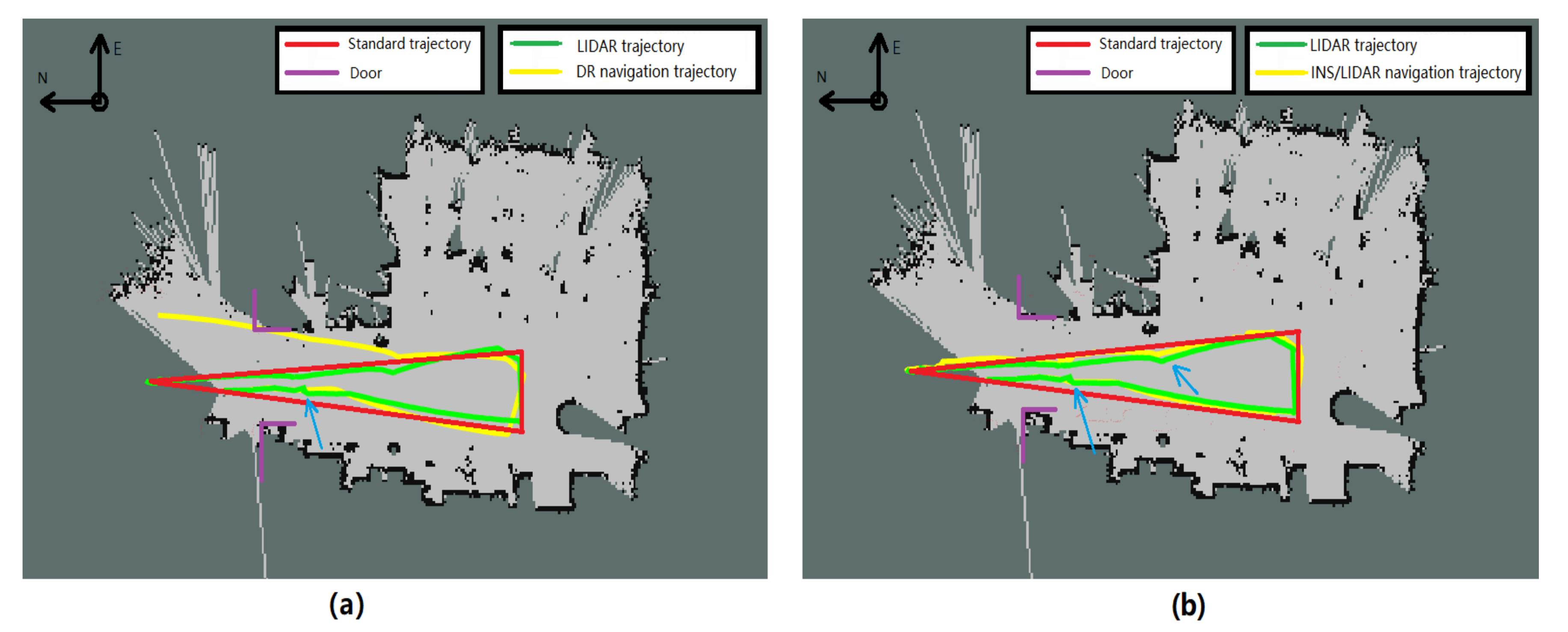
After discussing the indoor and outdoor switching navigation algorithm, the commercial vehicle will enter the area without GNSS satellite signals in the underground garage. The vehicle will rely on the inertial navigation DR algorithm or the INS/LIDAR integrated navigation algorithm for indoor positioning in this area. This paper still utilize the simulation robot to complete indoor navigation experiment. The experiment designs integrated positioning algorithm of the robot with the LIDAR plus inertial device to replace the actual vehicle location and draw the driving trajectory of the robot indoor. As shown in
Figure 7, the green trajectory is the robot’s driving trajectory with LIDAR independent mapping and positioning. The red line is the precalibrated indoor trajectory according to the Longitude and Latitude of the building, and it is regarded as the standard reference track in the indoor environment. First, it is essential to calibrate a coordinate point of Latitude and Longitude in the door area with a standard GPS receiver as an original point and establish a rectangular coordinate system. In the coordinate system, the north direction is the y axis and the east direction is the x axis. Then, we plan the robot trajectory in the indoor area and mark the inflection point of the robot trajectory. We need to measure relative position of each inflection point to the original point or other inflection point. At last, the precise Latitude and Longitude coordinates of the inflection point of the driving trajectory are calculated. The yellow trajectory is the driving track of the integrated navigation robot. It is directly connected with the outdoor GNSS/INS integrated navigation trajectory according to the EKF algorithm, and continue to derive the indoor Longitude and Latitude coordinates of the indoor relative position coordinate system.
Figure 7a,b displays the indoor driving trajectory of the robot. The yellow line in
Figure 7a is the driving trajectory of the robot’s inertial navigation DR algorithm, and
Figure 7b is the driving trajectory of the INS/LIDAR integrated navigation algorithm. There are three blue arrows in
Figure 7a,b. In these areas, the navigation trajectory of the green line has a sudden change. Because Hector SLAM algorithm matches the current map are different from the previous position and yaw angle. The algorithm will correct itself position to calibrate the map matching error. Hence, the vehicle position and yaw angle will change instantaneously. The INS/LIDAR integrated navigation algorithm of yellow line fixes the error in time and makes this trajectory smooth transition.
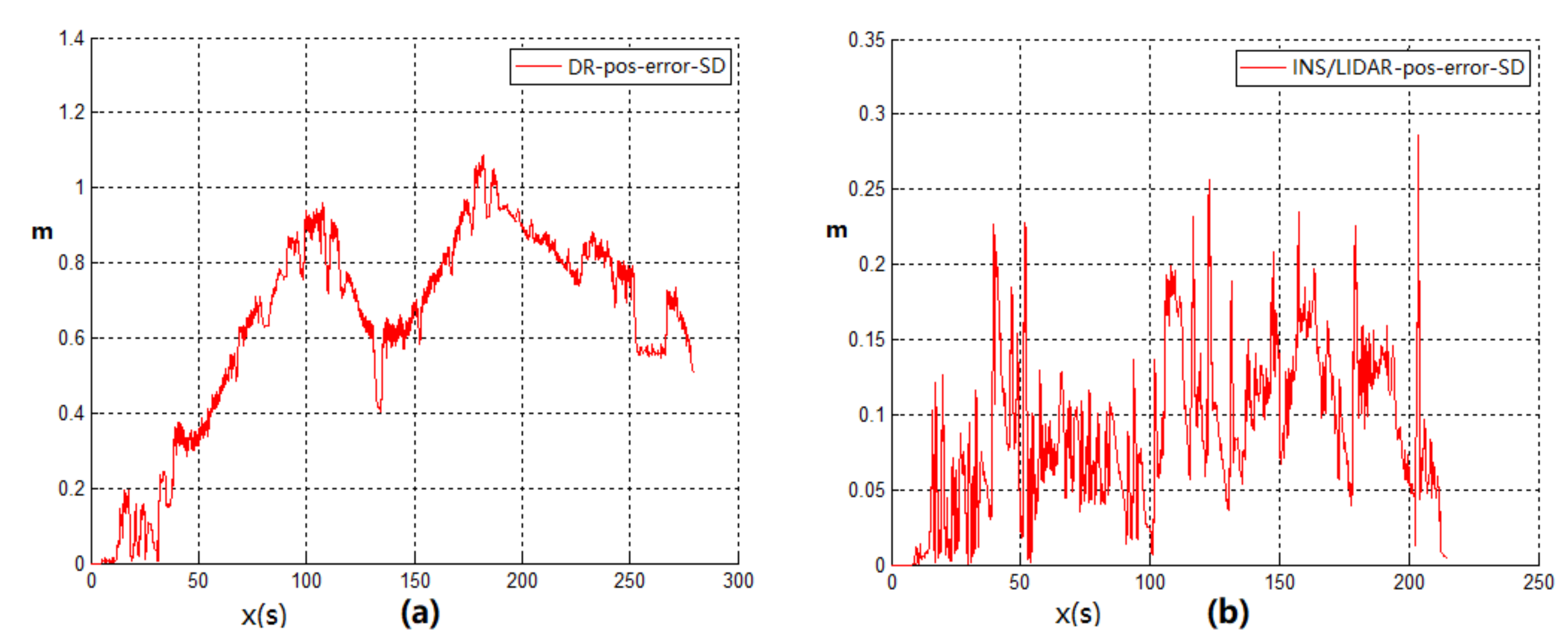
Figure 8a,b shows the Standard Deviation (SD) error of the position error of the robot’s position, and these error wave graph correspond to the
Figure 7a,b. The SD is calculated based on the standard trajectory. It can be seen from the error graph that the positioning error of the inertial navigation DR algorithm increases with time by 200 s and its standard deviation error is 1.25. Nevertheless, the positioning error of INS/LIDAR integrated navigation algorithm will not increase with time accumulation, and the positioning error has been kept below 0.25 continuously. After the above experiments operating, it can be proved that the positioning error will not diverge after the introduction of the LIDAR integrated navigation algorithm in indoor navigation, and the location accuracy is significantly enhanced.
The second part of Experiment 2 is to ensure the reliability of the robot experiment. The second experiment increases the running time of the robot, and conduct the experiment again after the expanded robot operation site. It is shown from
Figure 9a that the positioning error of the robot is gradually rising 300 s, as shown in
Figure 10a. The standard deviation error of the positioning error of the robot is about 0.8. In addition, the trajectory positioning error with LIDAR integrated navigation and positioning has been kept below 0.2, as shown in
Figure 9b and
Figure 10b. After operating the above experiment, the result shows that the LIDAR integrated navigation and positioning error will not increase with time accumulation. Its effort is better than the DR algorithm.
3.3. Experiment 3: Whole-process System Integrated Navigation Experiment with Simulation Robot
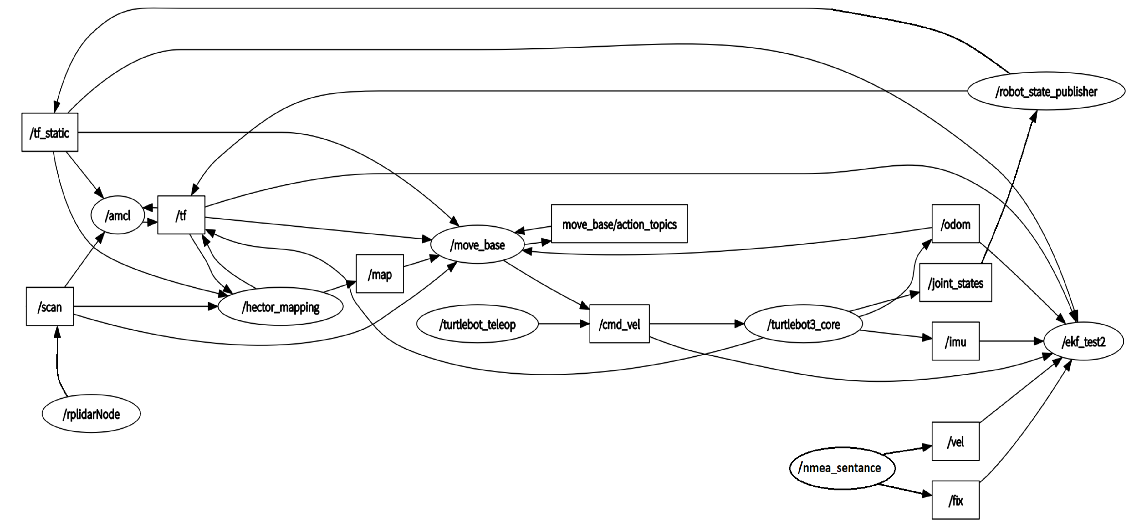
The third experiment conducts collaborative testing of indoor and outdoor integrated navigation algorithms. ROS simulation robot system software algorithm topic structure diagram is shown in the
Figure 11. The core algorithm of the integrated navigation system is written in “/ekf_test2” ROS topic and its final result is provided to screen. The core topic subscribes to the odometer topic “/odom”, inertial navigation measurement unit topic “/imu”, GNSS satellite receiver topic “/vel” and “/fix”. The robot system core control topic “/turtlebot3_core” remotely subscribe to the LIDAR scan result topic “/scan” and the converted map data “/map”. These data are presented on the screen as a two-dimensional SLAM map and driving trajectory.
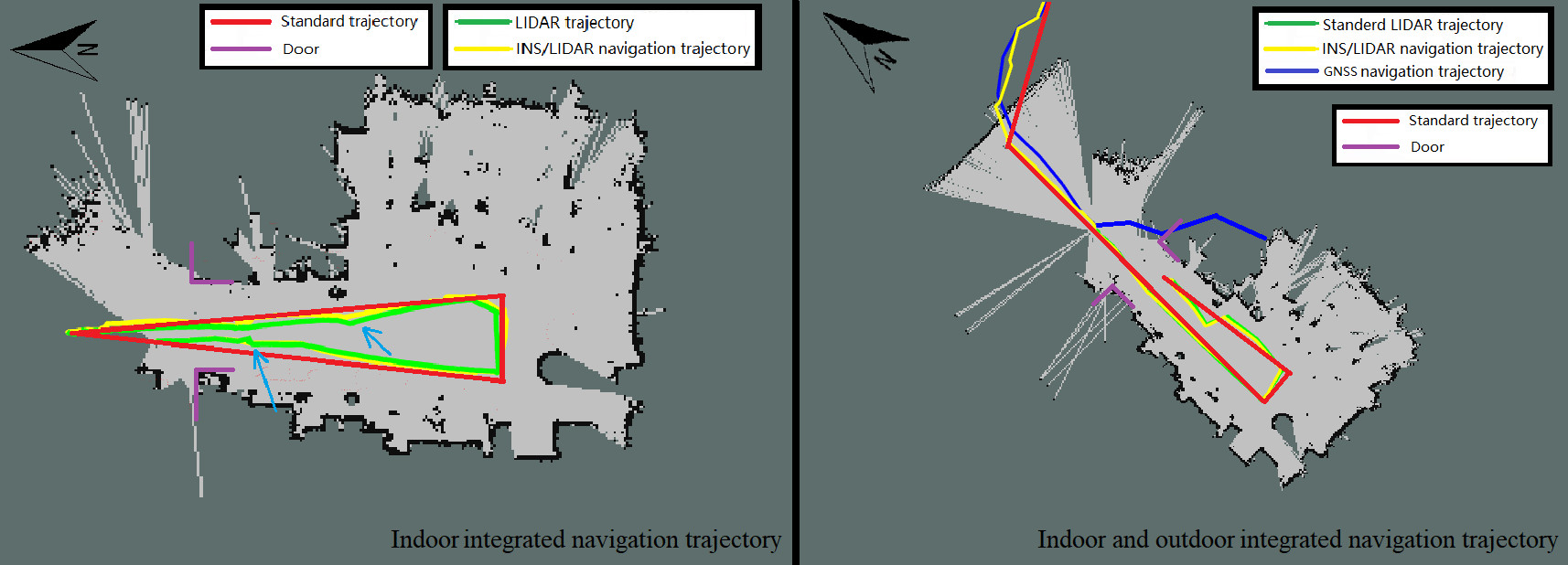
The trajectory map of indoor and outdoor simulation robot integrated navigation is shown in
Figure 12. The green line in the map is the trajectory of indoor LIDAR independent positioning. The blue line is the trajectory of outdoor GNSS positioning. It can be seen from the
Figure 12 that the blue line of GNSS location shows a higher positioning accuracy outdoors. When the robot enters the room, the GNSS positioning accuracy decreases at first and then the satellite positioning signal disappears at last. It is the normal phenomenon for the robot, owing to the GNSS signal is blocked by the building. The yellow line is the continuous indoor and outdoor integrated navigation and positioning trajectory. The outdoor navigation algorithm selects GNSS/INS integrated navigation and the indoor utilizes INS/LIDAR integrated navigation and positioning. When the navigation system mode is switched, the three positioning sensors are used simultaneously to achieve the best navigation and positioning effect.
The positioning accuracy parameters of the simulation robot are shown in
Table 1. The positioning parameters are achieved from the above three sets of experiments. According to the data, the positioning accuracy of the indoor LIDAR integrated navigation system is higher than that of the DR navigation algorithm. The indoor and outdoor integrated navigation error is 3.904 m.
4. Conclusions
GNSS satellite positioning in the outdoor environment is the best solution for navigation system, but due to the weak penetration of GNSS satellite signals, vehicles cannot receive GNSS satellite signals in the indoor garage. Therefore, the alternative navigation solutions has to be prepared. Different from high-cost and high-precision navigation equipment, the application method of low-cost navigation system is also different. After a variety of program comparisons, the multisensors integration scheme will properly meet the actual low-cost vehicle navigation needs in application.
After the theoretical analysis and experimental verification, the low-cost multisensor integrated navigation scheme can effectively solve and supplement the problem of missing positioning signals from outdoor to indoor. Due to the complex structure of the actual passenger vehicle and the confidentiality of the internal information in the vehicle control system for safety, the odometer information inside the vehicle cannot be required by the public. Therefore, the Hector mapping and positioning algorithms of the LIDAR that do not rely on the odometer positioning information is the best choice among all kinds of LIDAR SLAM algorithms. Then this paper takes the advantage of the four different types of sensors includes GNSS, LIDAR, inertial navigation and odometer. These sensors are integrated with Kalman filter navigation algorithm to provide a complete set of vehicle navigation solutions from outdoor to indoor. Ultimately, whether the vehicle is indoors or indoors, its Longitude and Latitude coordinates in the geographic coordinate system of the current location can be require by the system. The first experiment of the navigation system verifies the availability of the algorithm when the simulation robot platform switches the navigation state. The paper also supplements the LIDAR switching navigation algorithm, which further improves the accuracy and reliability of the positioning data when the mode is switched. The Experiment 2 of the navigation system was carried out indoors. The positioning accuracy of the DR navigation algorithm and INS/LIDAR integrated navigation algorithm were compared. At the same time, the reliability of LIDAR in indoor positioning was also proved. System Experiment 3 conducted indoor and outdoor complete navigation experiments, and analyzed the ROS system topic framework of the navigation algorithm program. After several simulation robot navigation and positioning experiments, the results proved that the multisensor integrated seamless navigation algorithm is a stable and reliable algorithm with high positioning accuracy.
According to the final experimental data, the positioning accuracy of the INS/LIDAR navigation algorithm in the simulated underground garage navigation experiment is 50%. It is higher than that of the DR navigation. In addition, after plenty of full-process experiments, the final switching algorithm with speed, the rate of the using ramp and GNSS signal detection navigation switching algorithm to achieve successful mode switching and keeping the underground garage navigation stable is only 50%. However, taking advantage of the INS/LIDAR integrated navigation switching algorithm can achieve an 80% mode switching success rate. This algorithm effectively improves the stability of the navigation switching algorithm.

 ,
, 


