

Review of Energy-Saving Technologies for Electric Vehicles, from the Perspective of Driving Energy Management

 ,
,  ,
,
Abstract
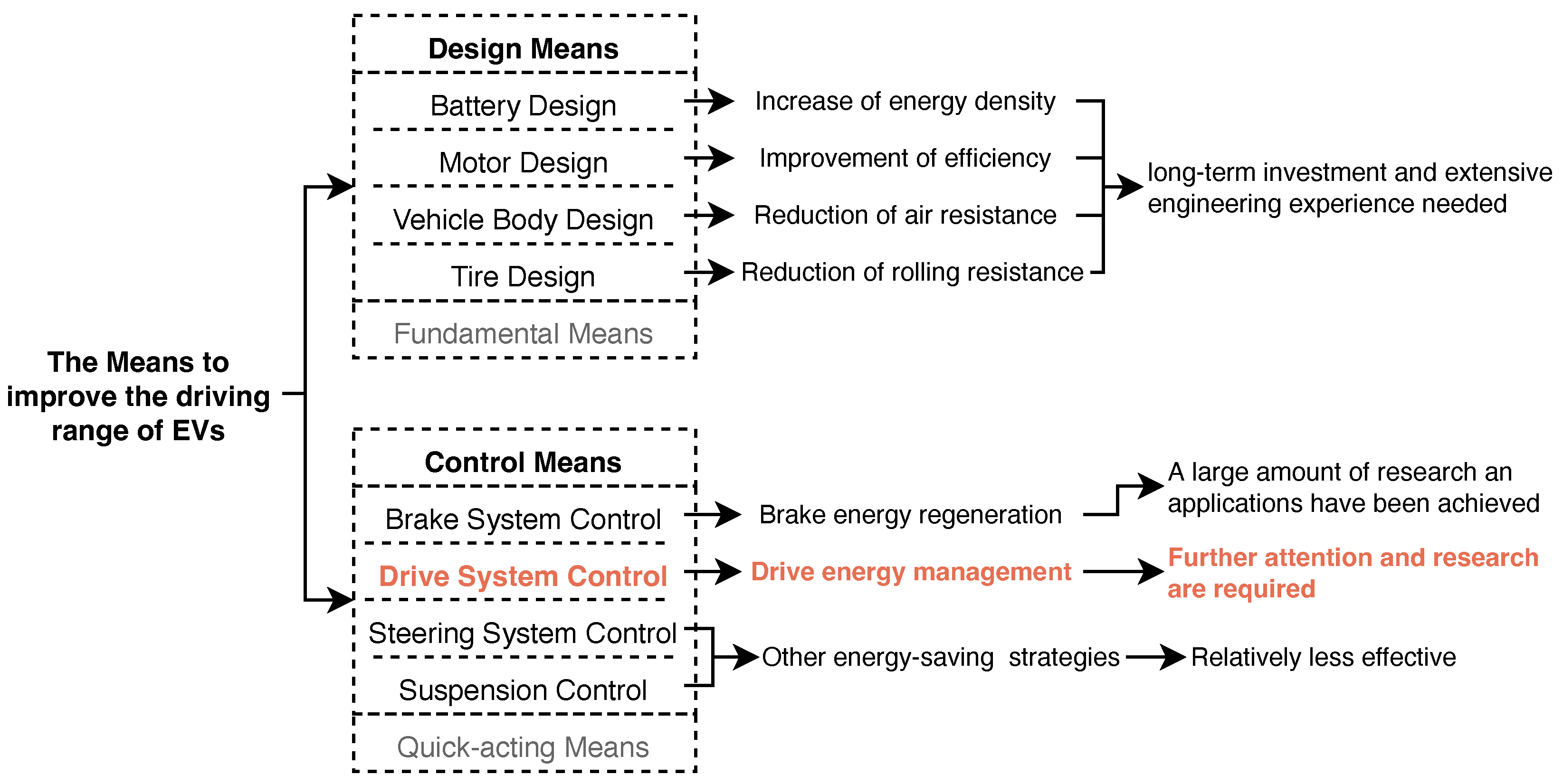
:1. Introduction
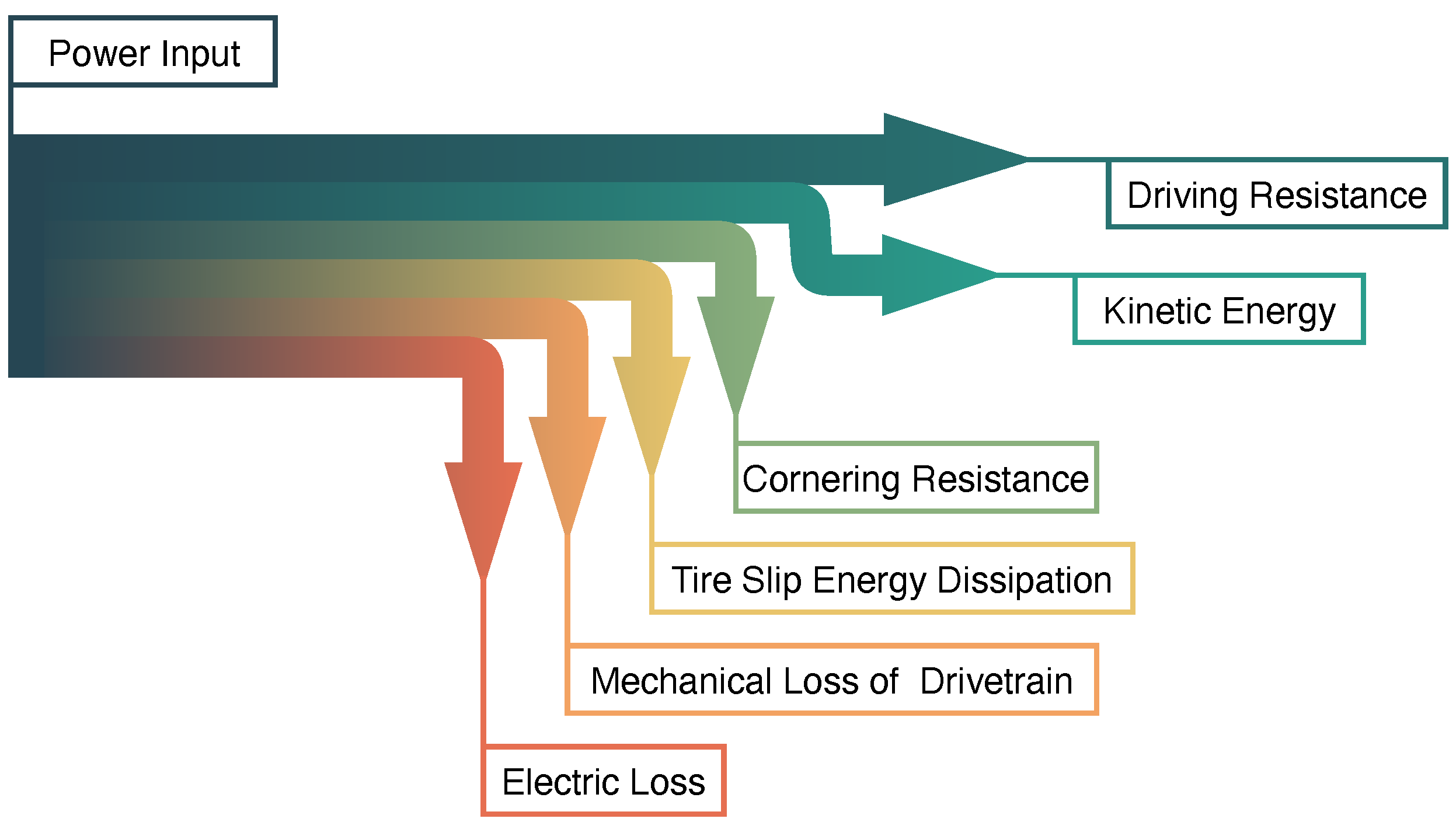
2. Driving Energy Loss Analysis
3. Dual-Motor Coupling Drive System
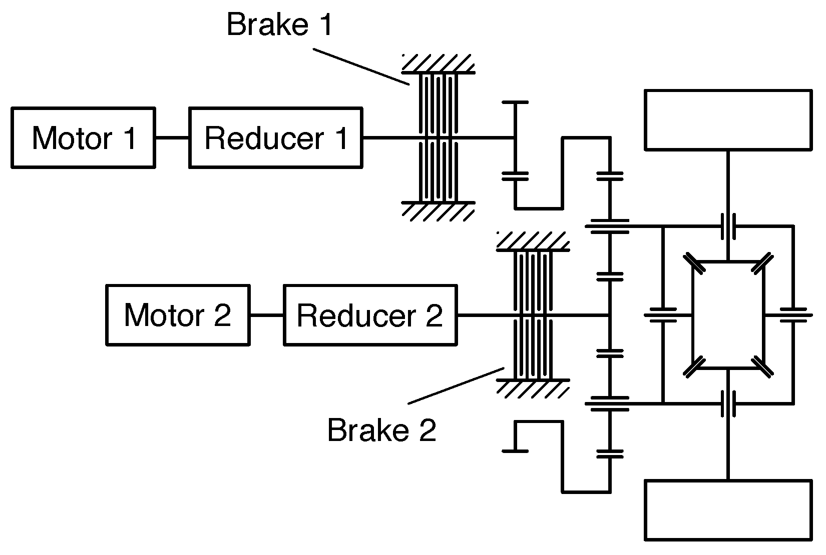
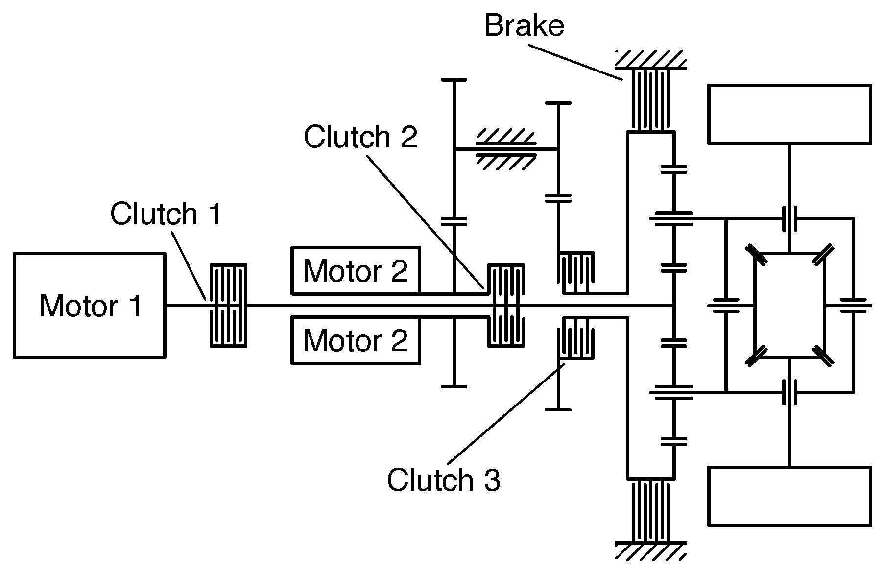
3.1. Configuration of DCDS
3.2. Power Distribution Strategy of DCDS
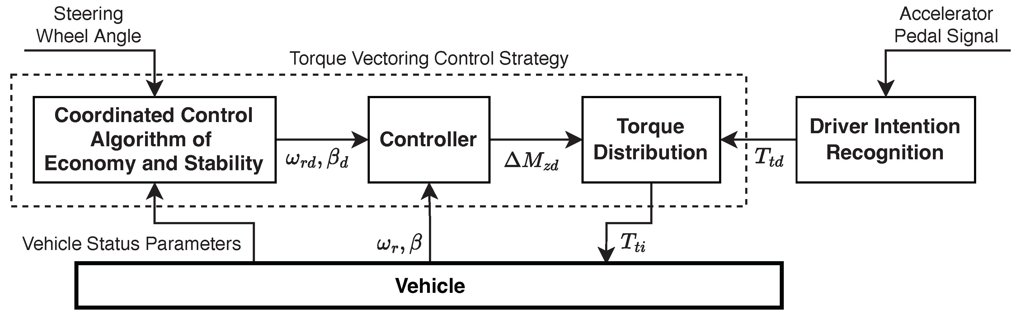
4. Energy Conservation Control Strategy of Torque Vectoring
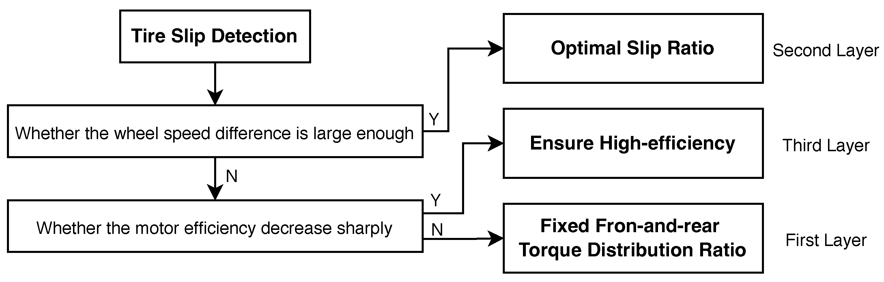
4.1. Front-and-Rear Torque Vectoring
4.2. Left-and-Right Torque Vectoring
5. Conclusions
Author Contributions
Funding
Data Availability Statement
Acknowledgments
Conflicts of Interest
References
- Chan, C.C.; Wong, Y.S. The state of the art of electric vehicles technology. In Proceedings of the 4th International Conference on Power Electronics and Motion Control, Xi’an, China, 14–16 August 2004; pp. 46–57. [Google Scholar]
- Hofmann, J.; Guan, D.; Chalvatzis, K.; Huo, H. Assessment of electrical vehicles as a successful driver for reducing CO2 emissions in China. Appl. Energy 2016, 184, 995–1003. [Google Scholar] [CrossRef]
- Zhan, W.; Wang, Z.; Deng, J.; Liu, P.; Cui, D.; Li, H. Analysis of influencing factors of carbon emission reduction in the driving stage of electric vehicles based on big data. Automot. Eng. 2022, 44, 1581–1590. [Google Scholar]
- Ali, A.M.; Moulik, B. On the role of intelligent power management strategies for electrified vehicles: A review of predictive and cognitive methods. IEEE Trans. Transp. Electrif. 2022, 8, 368–383. [Google Scholar] [CrossRef]
- Manzetti, S.; Mariasiu, F. Electric vehicle battery technologies: From present state to future systems. Renew. Sust. Energ. Rev. 2015, 51, 1004–1012. [Google Scholar] [CrossRef]
- Liu, Y.; Dong, X. Annual Report 2020 on Energy Density and Driving Range of Electric Vehicles. Automot. Dig. 2021, 550, 12–16. [Google Scholar]
- Vodovozov, V.; Raud, Z.; Petlenkov, E. Review on Braking Energy Management in electric vehicles. Energies 2021, 14, 4477. [Google Scholar] [CrossRef]
- Fleming, B. Electric vehicle collaboration-toyota motor corporation and tesla motors. IEEE Veh. Technol. Mag. 2013, 8, 4–9. [Google Scholar]
- Von Albrichsfeld, C.; Karner, J. Brake System for Hybrid and Electric Vehicles; SAE Technical Paper; SAE: Warrendale, PA, USA, 2009. [Google Scholar]
- Shirase, T.; Sakai, K.; Aoki, Y.; Suzuki, K.; Nakano, H.; Akamine, K. Development of Hydraulic Servo Brake System for Cooperative Control with Regenerative Brake; SAE: Warrendale, PA, USA, 2007. [Google Scholar]
- Yang, F.; Zhang, B.; Lyu, Q.; Zhang, X. Development and trends of dual-motor coupling drive system in electric vehicles. Chin. J. Automot. Eng. 2022, 12, 105–113, 136. [Google Scholar]
- Wang, J.; Yang, B.; Wang, Q.; Ni, J. Review on vehicle drive technology of torque vectoring. J. Mech. Eng. 2020, 56, 92–104. [Google Scholar]
- Qi, X.; Wang, Q.; Chen, L.; Cao, J.; Zhang, Q.; Li, G. Optimization strategies of torque distribution for front and rear dual motor driven electric vehilces. Electr. Mach. Control 2020, 24, 62–70, 78. [Google Scholar]
- Gu, J.; Ouyang, M.; Lu, D.; Li, J.; Lu, L. Energy efficiency optimization of electric vehicle driven by in-wheel motors. Int. J. Automot. Technol. 2013, 14, 763–772. [Google Scholar] [CrossRef]
- Suzuki, Y.; Kano, Y.; Abe, M. A study on tyre force distribution controls for full drive-by-wire electric vehicle. Veh. Syst. Dyn. 2014, 52, 235–250. [Google Scholar] [CrossRef]
- Sun, W.; Wang, Q.; Wang, J. Yaw-moment control of motorized vehicle for energy conservation during cornering. J. Jilin Univ. 2018, 48, 11–19. [Google Scholar]
- Kobayashi, T.; Katsuyama, E.; Sugiura, H.; Ono, E.; Yamamoto, M. Direct yaw moment control and power consumption of in-wheel motor vehicle in steady-state turning. Veh. Syst. Dyn. 2017, 55, 104–120. [Google Scholar] [CrossRef]
- Sun, W.; Wang, J.N.; Wang, Q.N.; Assadian, F.; Fu, B. Simulation investigation of tractive energy conservation for a cornering rear-wheel-independent-drive electric vehicle through torque vectoring. Sci. China-Technol. Sci. 2018, 61, 257–272. [Google Scholar] [CrossRef]
- Fujimoto, H.; Sumiya, H. Range Extension Control System of Electric Vehicle Based on Optimal Torque Distribution and Cornering Resistance Minimization. In Proceedings of the ICELIE/IES Industry Forum/37th Annual Conference of the IEEE Industrial-Electronics-Society (IECON), Melbourne, Australia, 7–10 November 2011; pp. 3858–3863. [Google Scholar]
- Rill, G. Reducing the cornering resistance by torque vectoring. In Proceedings of the 10th International Conference on Structural Dynamics (EURODYN), Rome, Italy, 10–13 September 2017; pp. 3284–3289. [Google Scholar]
- Hua, Y.; Zhang, J.; Wen, X. High power Dual Motor Drive System used in Fuel Cell vehicles. In Proceedings of the 2008 IEEE Vehicle Power and Propulsion Conference, Harbin, China, 3–5 September 2008. [Google Scholar]
- Sorniotti, A.; Holdstock, T.; Everitt, M.; Fracchia, M. A Novel Clutchless Multiple–Speed Transmission for Electric Axles; University of Surrey: Guildford, UK; Warwick, UK; Volume 2, pp. 103–131.
- Hu, J.J.; Zheng, L.L.; Jia, M.X.; Zhang, Y.; Pang, T. Optimization and model validation of operation control strategies for a novel dual-motor coupling-propulsion pure electric vehicle. Energies 2018, 11, 754. [Google Scholar] [CrossRef]
- Coronado, P.D.U.; Ahuett-Garza, H. Analysis of Energy Efficiency and Driving Range of Electric Vehicles Equipped with a Bimotor Architecture Propulsion System; Center for Innovation, Design and Technology, Tecnológico de Monterrey, Campus Monterrey: Monterrey, Mexico, 2014; Volume 6, pp. 152–177. [Google Scholar]
- Wu, X.; Yin, X. Control of a dual-motor coupling drive system on electric vehicles buses. Chin. High Technol. Lett. 2013, 23, 863–867. [Google Scholar]
- Zhang, C.; Wu, X.; Wang, Z.; Tian, Z. Mode switching control strategy of dual motors coupled driving on electric vehicles. J. Beijing Inst. Technol. 2011, 20, 394–398. [Google Scholar]
- Sun, D.; Chen, Z. Parameters matching and design of dual-drive electric vehicle transmission system under NEDC working conditions. Intern. Combust. Engines 2013, 4, 22–25, 39. [Google Scholar]
- Zhang, S.; Xiong, R.; Zhang, C.N.; Sun, F.C. An optimal structure selection and parameter design approach for a dual-motor-driven system used in an electric bus. Energy 2016, 96, 437–448. [Google Scholar] [CrossRef]
- Wang, Y.; Sun, D.Y. Powertrain matching and optimization of dual-motor hybrid driving system for electric vehicle based on quantum genetic intelligent algorithm. Discrete Dyn. Nat. Soc. 2014, 2014, 11. [Google Scholar] [CrossRef]
- Hu, M.H.; Zeng, J.F.; Xu, S.Z.; Fu, C.Y.; Qin, D.T. Efficiency study of a dual-motor coupling electric vehicles powertrain. IEEE Trans. Veh. Technol. 2015, 64, 2252–2260. [Google Scholar] [CrossRef]
- Wang, J.; Liu, D.; Zhang, Y.; Sun, W.; Chu, L. Analysis of energy conservation potential of novel pure electric vehicle with dual motors configuration. J. Jilin Univ. 2016, 46, 28–34. [Google Scholar]
- Zhang, S.; Xiong, R.; Zhang, C.N. Pontryagin’s minimum principle-based power management of a dual-motor-driven electric bus. Appl. Energy 2015, 159, 370–380. [Google Scholar] [CrossRef]
- Meng, X.; Wang, R.; Xu, Y. Torque distribution strategy of pure electric driving mode for dual planetary vehicle. J. Zhejiang Univ. 2020, 54, 2214–2223, 2246. [Google Scholar]
- Zhang, S.; Zhang, C.N.; Han, G.W.; Wang, Q.H. Optimal control strategy design based on dynamic programming for a dual-motor coupling-propulsion system. Sci. World J. 2014, 2014, 958239. [Google Scholar] [CrossRef]
- Gao, Y.; Wang, W.; Li, Y. Optimization of control strategy for dual-motor coupling propulsion system based on dynamic programming method. In Proceedings of the the 3rd Annual Academic Meeting of Vehicle Control and Intelligence Professional Committee of China Association of Automation, Beijing, China, 21–22 September 2019. [Google Scholar]
- Wahl, H.-G.; Gauterin, F. An iterative dynamic programming approach for the global optimal control of hybrid electric vehicles under real-time constraints. In Proceedings of the 2013 IEEE Intelligent Vehicles Symposium (IV), Gold Coast, QLD, Australia, 1 December 2013. [Google Scholar]
- Larsson, V.; Johannesson, L.; Egardt, B. Analytic solutions to the dynamic programming subproblem in hybrid vehicle energy management. IEEE Trans. Veh. Technol. 2015, 64, 1458–1467. [Google Scholar] [CrossRef]
- Lin, C.; Zhao, M.J.; Pan, H.; Shao, S. Energy management for a dual-motor coupling propulsion electric bus based on model predictive control. In Proceedings of the 10th International Conference on Applied Energy (ICAE), Hong Kong, China, 22–25 August 2018; pp. 2744–2749. [Google Scholar]
- Zhang, C.N.; Zhang, S.; Han, G.W.; Liu, H.P. Power management comparison for a dual-motor-propulsion system used in a battery electric bus. IEEE Trans. Ind. Electron. 2017, 64, 3873–3882. [Google Scholar] [CrossRef]
- Qian, H.; Xu, G.; Yan, J.; Lam, T.; Xu, Y.; Xu, K. Energy management for four-wheel independent driving vehicle. In Proceedings of the IEEE/RSJ International Conference on Intelligent Robots and Systems, Taipei, Taiwan, 18–22 October 2010; pp. 5532–5537. [Google Scholar]
- Yang, Y.-P.; Shih, Y.-C.; Chen, J.-M. Real-time torque-distribution strategy for a pure electric vehicle with multiple traction motors by particle swarm optimization. IET Electr. Syst. Transp. 2016, 6, 76–87. [Google Scholar] [CrossRef]
- Kim, H.-W.; Amarnathvarma, A.; Kim, E.; Hwang, M.-H.; Kim, K.; Kim, H.; Choi, I.; Cha, H.-R. A novel torque matching strategy for dual motor-based all-wheel-driving electric vehicles. Energies 2022, 15, 2717. [Google Scholar] [CrossRef]
- Yang, Z.; Wang, J.; Gao, G.; Shi, X. Research on optimized torque-distribution control method for front/rear axle electric wheel loader. Math. Probl. Eng. 2017, 2017, 12. [Google Scholar] [CrossRef]
- Huang, J.; Liu, Y.; Liu, M.; Cao, M.; Yan, Q. Multi-objective optimization control of distributed electric drive vehicles based on optimal torque distribution. IEEE Access 2019, 7, 16377–16394. [Google Scholar] [CrossRef]
- Yuan, X.B.; Wang, J.B. Torque distribution strategy for a front-and rear-wheel-driven electric vehicle. IEEE Trans. Veh. Technol. 2012, 61, 3365–3374. [Google Scholar] [CrossRef]
- Gu, C.; Liu, H.; Chen, X. Torque distribution based on efficiency optimization of four-wheel independent drive electric vehicle. J. Tongji Univ. 2015, 43, 1550–1556. [Google Scholar]
- Yu, Z.; Zhang, L.; Xiong, L. Optimized torque distribution control of achieve higher fuel economy of 4WD electric vehicle with four in-wheel motors. J. Tongji Univ. 2005, 33, 1355. [Google Scholar]
- Dizqah, A.M.; Lenzo, B.; Sorniotti, A.; Gruber, P.; Fallah, S.; Smet, J.D. A fast and parametric torque distribution strategy for four-wheel-drive energy-efficient electric vehicles. IEEE Trans. Ind. Electron. 2016, 63, 4367–4376. [Google Scholar] [CrossRef]
- Lenzo, B.; De Filippis, G.; Dizqah, A.M.; Sorniotti, A.; Gruber, P.; Fallah, S.; De Nijs, W. Torque distribution strategies for energy-efficient electric vehicles with multiple drivetrains. J. Dyn. Syst. Meas. Control 2017, 139, 121004. [Google Scholar] [CrossRef]
- Lu, D.; Ouyang, M.; Gu, J.; Li, J. Torque distribution algorithm for a permanent brushless DC hub motor for four-wheel drive electric vehicles. J. Tsinghua Univ. 2012, 52, 451–456. [Google Scholar]
- Wu, D.; Zheng, M.; Li, Y.; Du, C. Predictive energy saving control for intelligent 4WD Electric Vehicle. J. Tongji Univ. 2017, 45, 63–68. [Google Scholar]
- Li, Y.; Zhang, J.; Guo, K.; Wu, D. Optimized torque distribution algorithm to improve the energy efficiency of 4WD electric vehicle. In Proceedings of the SAE 2014 Commercial Vehicle Engineering Congress, COMVEC 2014, Rosemont, IL, USA, 7–9 October 2014. [Google Scholar]
- Wang, Y.; Fujimoto, H.; Hara, S. Torque distribution-based range extension control system for longitudinal motion of electric vehicles by LTI modeling with generalized frequency variable. IEEE/Asme Trans. Mechatron. 2016, 21, 443–452. [Google Scholar] [CrossRef]
- Sun, B.B.; Gao, S.; Ma, C.; Li, J.W. System power loss optimization of electric vehicle driven by front and rear induction motors. Int. J. Automot. Technol. 2018, 19, 121–134. [Google Scholar] [CrossRef]
- Guo, C.; Chunyun, F.; Zhai, J.; Cao, K.; Luo, R.; Liu, Y.; Pan, H.; Qiao, S. Coordinated control of torque distribution and acceleration slip regulation for front-and rear-indepnedent-drive electric vehicles. J. Chongqing Univ. 2022, 45, 97–112. [Google Scholar]
- Ou, Y.; Wang, P.; Xu, L.; Fan, J.; Zhou, Z.; Li, Z.; Bai, Q.; Zhang, Y.; Gao, Z. Torque allocation strategy for two axles four wheel drive electric vehicle with improvement of economy and stability. J. Phys. Conf. Ser. 2020, 1550, 042020. [Google Scholar] [CrossRef]
- Cao, K.B.; Hu, M.H.; Wang, D.Y.; Qiao, S.P.; Guo, C.; Fu, C.Y.; Zhou, A.J. All-wheel-drive torque distribution strategy for electric vehicle optimal efficiency considering tire slip. IEEE Access 2021, 9, 25245–25257. [Google Scholar] [CrossRef]
- Sawase, K.; Ushiroda, Y.; Inoue, K. Effect of the right-and-left torque vectoring system in various types of drivetrains. In Proceedings of the 14th Asia Pacific Automotive Engineering Conference, Hollywood, CA, USA, 5–8 August 2007. [Google Scholar]
- Cheli, F.; Cimatti, F.; Dellacha, P.; Zorzutti, A. Development and implementation of a torque vectoring algorithm for an innovative 4WD driveline for a high-performance vehicle. Veh. Syst. Dyn. 2009, 47, 179–193. [Google Scholar] [CrossRef]
- Wong, A.; Kasinathan, D.; Khajepour, A.; Chen, S.K.; Litkouhi, B. Integrated torque vectoring and power management framework for electric vehicles. Control Eng. Pract. 2016, 48, 22–36. [Google Scholar] [CrossRef]
- Wang, J.; Luo, Z.; Wang, Y.; Yang, B.; Assadian, F. Coordination control of differential drive assist steering and vehicle stability control for four-wheel-independent-drive electric vehicles. IEEE Trans. Veh. Technol. 2018, 67, 11453–11467. [Google Scholar] [CrossRef]
- Pennycott, A.; De Novellis, L.; Sabbatini, A.; Gruber, P.; Sorniotti, A. Reducing the motor power losses of a four-wheel drive, fully electric vehicle via wheel torque allocation. Proc. Inst. Mech. Eng. Part J. Automob. Eng. 2014, 228, 830–839. [Google Scholar] [CrossRef]
- De Filippis, G.; Lenzo, B.; Sorniotti, A.; Gruber, P.; De Nijs, W. Energy-efficient torque-vectoring control of electric vehicles with multiple drivetrains. IEEE Trans. Veh. Technol. 2018, 67, 4702–4715. [Google Scholar] [CrossRef]
- Zhao, B.; Xu, N.; Chen, H.; Guo, K.H.; Huang, Y.J. Design and experimental evaluations on energy-efficient control for 4WIMD-EVs considering tire slip energy. IEEE Trans. Veh. Technol. 2020, 69, 14631–14644. [Google Scholar] [CrossRef]
- Wang, J.N.; Gao, S.L.; Wang, K.; Wang, Y.; Wang, Q.S. Wheel torque distribution optimization of four-wheel independent-drive electric vehicle for energy efficient driving. Control Eng. Practice 2021, 110, 14. [Google Scholar] [CrossRef]
- Wang, J.; Yu, T.; Sun, N.; Fu, T. Torque vectoring control of rear-wheel-independent-drive vehicle for cornering efficiency improvement. J. Hunan Univ. 2020, 47, 9–17. [Google Scholar]
- De Novellis, L.; Sorniotti, A.; Gruber, P. Optimal wheel torque distribution for a four-wheel-drive fully electric vehicle. SAE Int. J. Passeng. Cars-Mech. Syst. 2013, 6, 128–136. [Google Scholar] [CrossRef]
- Koehler, S.; Viehl, A.; Bringmann, O.; Rosenstiel, W. Improved energy efficiency and vehicle dynamics for battery electric vehicles through torque vectoring control. In Proceedings of the 2015 IEEE Intelligent Vehicles Symposium (IV), Seoul, Republic of Korea, 28 June–1 July 2015; pp. 749–754. [Google Scholar]
- Koehler, S.; Viehl, A.; Bringmann, O.; Rosenstiel, W. Energy-efficiency optimization of torque vectoring control for battery electric vehilces. IEEE Intell. Transp. Syst. Mag. 2017, 9, 59–74. [Google Scholar] [CrossRef]
- Parra, A.; Tavernini, D.; Gruber, P.; Sorniotti, A.; Zubizarreta, A.; Perez, J. On nonlinear model predictive control for energy-efficient torque-vectoring. IEEE Trans. Veh. Technol. 2021, 70, 173–188. [Google Scholar] [CrossRef]
- Chatzikomis, C.; Zanchetta, M.; Gruber, P.; Sorniotti, A.; Modic, B.; Motaln, T.; Blagotinsek, L.; Gotovac, G. An energy-efficient torque-vectoring algorithm for electric vehicles with multiple motors. Mech. Syst. Signal Process. 2019, 128, 655–673. [Google Scholar] [CrossRef]
- Han, Z.L.; Xu, N.; Chena, H.; Huang, Y.J.; Zhao, B. Energy-efficient control of electric vehicles based on linear quadratic regulator and phase plane analysis. Appl. Energy 2018, 213, 639–657. [Google Scholar] [CrossRef]
- Wei, H.; Zhang, N.; Liang, J.; Ai, Q.; Zhao, W.; Huang, T.; Zhang, Y. Deep reinforcement learning based direct torque control strategy for distributed drive electric vehicles considering active safety and energy saving performance. Energy 2022, 238, 121725. [Google Scholar] [CrossRef]
- Wang, R.R.; Chen, Y.; Feng, D.W.; Huang, X.Y.; Wang, J.M. Development and performance characterization of an electric ground vehicle with independently actuated in-wheel motors. J. Power Sources 2011, 196, 3962–3971. [Google Scholar] [CrossRef]
- Najjari, B.; Mirzaei, M.; Tahouni, A. Decentralized integration of constrained active steering and torque vectoring systems to energy-efficient stability control of electric vehicles. J. Frankl. Inst. 2022, 359, 8713–8741. [Google Scholar] [CrossRef]
- Vignati, M.; Sabbioni, E. A cooperative control strategy for yaw rate and sideslip angle control combining torque vectoring with rear wheel steering. Veh. Syst. Dyn. 2022, 60, 1668–1701. [Google Scholar] [CrossRef]
- Edrén, J.; Jonasson, M.; Jerrelind, J.; Stensson Trigell, A.; Drugge, L. Energy efficient cornering using over-actuation. Mechatronics 2019, 59, 69–81. [Google Scholar] [CrossRef]


| DCDS Configuration | Coupling Output Torque | Coupling Output Speed | Feasible Driving Modes |
|---|---|---|---|
| DTCDS | Linear summation of the output torque of the two motors | Proportional to the output speed of the two motors | Single-motor drive mode and dual-motor torque-coupling driving mode |
| DSCDS | Proportional to the output torque of the two motors | Linear summation of the output speed of the two motors | Single-motor drive mode and dual-motor speed-coupling driving mode |
Disclaimer/Publisher’s Note: The statements, opinions and data contained in all publications are solely those of the individual author(s) and contributor(s) and not of MDPI and/or the editor(s). MDPI and/or the editor(s) disclaim responsibility for any injury to people or property resulting from any ideas, methods, instructions or products referred to in the content. |
© 2023 by the authors. Licensee MDPI, Basel, Switzerland. This article is an open access article distributed under the terms and conditions of the Creative Commons Attribution (CC BY) license (https://creativecommons.org/licenses/by/4.0/).
Share and Cite
Wang, D.; Guan, C.; Wang, J.; Wang, H.; Zhang, Z.; Guo, D.; Yang, F. Review of Energy-Saving Technologies for Electric Vehicles, from the Perspective of Driving Energy Management. Sustainability 2023, 15, 7617. https://doi.org/10.3390/su15097617
Wang D, Guan C, Wang J, Wang H, Zhang Z, Guo D, Yang F. Review of Energy-Saving Technologies for Electric Vehicles, from the Perspective of Driving Energy Management. Sustainability. 2023; 15(9):7617. https://doi.org/10.3390/su15097617
Chicago/Turabian StyleWang, Deping, Changyang Guan, Junnian Wang, Haisheng Wang, Zhenhao Zhang, Dachang Guo, and Fang Yang. 2023. "Review of Energy-Saving Technologies for Electric Vehicles, from the Perspective of Driving Energy Management" Sustainability 15, no. 9: 7617. https://doi.org/10.3390/su15097617