Article

Enhancing the Fatigue Design of Mechanical Systems Such as Refrigerator to Reserve Food in Agroindustry for the Circular Economy

1
Manufacturing Technology, Mechanical Technology Faculty, Ethiopian Technical University, Addis Ababa P.O. Box 190310, Ethiopia
2
Department of Mechanical Engineering, School of Engineering and Computer Science, Baylor University, Waco, TX 76798-7356, USA
*
Author to whom correspondence should be addressed.
Sustainability 2023, 15(8), 7010; https://doi.org/10.3390/su15087010
Submission received: 14 February 2023 / Revised: 8 March 2023 / Accepted: 20 April 2023 / Published: 21 April 2023
(This article belongs to the Special Issue Toward a Circular Economy in the Agro-Industrial and Food Sectors)

Abstract

:
To prolong the fatigue life of a product handled by machines such as refrigerators and agricultural machinery, parametric accelerated life testing (ALT) is recommended as a systemized approach to detect design inadequacies and reduce fatigue. It demands (1) an ALT strategy, (2) a fatigue type, (3) parametric ALTs with change, and (4) an estimate of whether the present product completes the BX lifetime. The utilization of a quantum-transported life-stress type and a sample size are advocated. The enhancements in the lifetime of a refrigerator ice-maker, containing an auger motor with bearings, were employed as a case study. In the 1st ALT, a steel rolling bearing cracked due to repeated loading under cold conditions (below −20 °C) in the freezer compartment. The bearing material was changed from an AISI 52100 Alloy Steel with 1.30–1.60% chromium to a lubricated sliding bearing with sintered and hardened steel (FLC 4608-110HT) because of its high fatigue strength at lower temperatures. In the 2nd ALT, a helix made of polycarbonates (PCs) fractured. In the redesign, a reinforced rib of the helix was thickened. Because no troubles in the 3rd ALT happened, the life of an ice-maker was proven to have a B1 life 10 years.

1. Introduction

To have mechanical systems, such as refrigerators, be competitive in the marketplace, their designs should incorporate the newest scientific and engineering knowledge and perform to the satisfaction of customers in the marketplace. If a system or product with new features is introduced into the market with insufficient testing, there is the possibility for early failure of the product due to the inferior design of the new features in the product. These premature failures in the market will undesirably influence the perceived quality of the product and affect the nature and environmental change in the global market related to sustainability. Moreover, many consumers will be forced to discard the faulty product and produce useless garbage. In an ideal case, design defects would be identified before the product was introduced in the market. This identification process would help reduce waste because products would be used for their fully anticipated lifetime before being replaced. To avoid discovering unanticipated design defects after the product is released and reinforce the proposition of “zero waste” in the market, any new traits for a product should be evaluated in the development process before being launched to the end-user. Assessing the reliability of a new mechanical system should include a structured method with reliability quantitative (RQ) statements [1]. Improving the reliability of a product should reduce or prevent waste from poorly designed products. Thus, this procedure should help improve sustainability with regard to the launch of new products in the market.
One feature of many new refrigerators is the ice-maker. Typically, these include an auger motor with a bearing designed to attain sufficient torque to sufficiently crush ice for discharge through the dispenser. The auger achieves decreasing speed through several gears engaged with a driving gear mounted in the shaft. The auger must operate under the low temperature condition (−20 °C↓) in the freezer compartment. It is subjected to repeated stresses supported by bearings. A common material utilized in the ball bearing rings is the alloy steel AISI 52100 because it is simply forged, heat-treated, and machined. This steel is commonly used in numerous products because of its durability [2,3,4,5] and, under normal circumstances, it can be integrated into designs so a product will provide a long life under normal circumstances for customers.
A lack of reliability can have severe negative consequences. For example, two Boeing 737 MAXs crashed, resulting in the death of 346 passengers. The plane was grounded from March 2019 to December 2020. The airplane used the CFM International LEAP-1B engines, adopting the most effective 68-inch fan design. They were 12% more fuel efficient and 7% more lightweight than previous engines [6]. Inspectors had conjectured that the accident was caused by the engine in the aircraft. As a result, the whole economy experienced the elimination of loss of parts (or wastes) due to an improper design. Possible troublesome components thus needed to be confirmed by laboratory testing to produce a reliability quantitative (RQ) expression [7,8,9].
Fatigue is the main origin of metallic failure in the structure, explaining approximately 80–95% of all failures [10]. It displays itself in the form of cracks which usually start from stress raisers, such as holes, slender surfaces, grooves, etc., on the structure of systems. Fatigue is the failure of a material that is frequently subjected to cyclic loading. Of particular concern is the failure of components during low-cycle fatigue, specifically in the area of turbine–engine that is composed of nickel-built polycrystalline matter [11,12]. It is also measured as a quantity element, such as the stress proportion, R (=σminmax), explained as the correlation of the greatest cyclic stress to the least cyclic stress [13]. Utilizing a stress proportion, R, presented in an ALT, should help identify the design defects in the mechanical system.
Designers have frequently recognized design imperfections and have fixed them by utilizing techniques such as Taguchi’s method [14]. In particular, the design of experiments (DOE) [15] is an organized method used to discover the connection between the factors governing a procedure and its production. The goal is to confirm that the factors are placed in the most successful manner for performing (or environmental) situations. The DOE is executed for related factors that determine product designs. Their functionality is revealed by an analysis of variance (ANOVA). Because a person who operates a DOE may not know which factors are the most influential in a failure, there is no specified process for identifying fatigue failure in the calculations. Thus, the DOE may require a large number of mathematical calculations and may not identify a potential source of failure.
Designers have frequently utilized the strength of materials as a solution to help in a conventional design [16,17,18]. A crucial element in fracture mechanics [19] is toughness as a material attribute of strength. With the implementation of quantum mechanics, engineers have pinpointed that structural failures occur from nanoscale or microscale voids, which may occur in metallic alloys or engineering plastics. As finite samples and limited testing periods are utilized [20,21,22,23,24], this method cannot reproduce the design flaws in a complex form or identify the fatigue problems that may occur with the product because of the specific way consumers use the product in the market. To discover the fatigue phenomena in a system functioning by machinery, a life-stress type [25,26] can be integrated with a (quantum) mechanics way to distinguish a prevailing defect or crack form in matter because unsuccessfulness stochastically happens in the region of particularly big stress.
The finite element method (FEM) [27] is utilized in a different way. Designers propose that failures may be determined by (1) an appropriate mathematical (Lagrangian or Newtonian) formulation; (2) deriving the time response for loads, generating the stress/strain on the part structure; (3) employing the generally accepted method of rain-flow counts with von Mises stress [28]; and (4) evaluating system effectiveness by Palmgren–Miner’s principle [29]. Deploying this methodology shall give closed-formation answers. However, this method cannot pinpoint fatigue failures in a complex system produced by structural defects such as microvoids, sharp edges, slender surfaces, etc.
This investigation proposes parametric ALT as a straightforward approach to identify the structural flaws of a new product and improve the reliability of the product. It involves the following: (1) an ALT scheme developed on the BX lifetime, (2) load study, (3) ALTs with the structure alterations, and (4) an appraisal of whether the system structure fulfills the objective BX lifetime. This procedure for recognizing the root causes and enhancing design examines properness in the mechanical products such as refrigerators, agricultural machinery, automobiles, etc. By eliminating problematic materials (AISI 52100 Alloy Steel) from being used in a product, it can help improve the reliability of the product, and reduce waste because the consumer is able to utilize the product longer. Furthermore, this experimental, computational, and theoretical research relating to natural and applied engineering will improve the human lifestyle in economics, social sciences, and the humanities and allow forecasts and effect evaluations of worldwide transform and evolution related to sustainability. The quantum-transported failure type and sample size are also advocated. A new refrigerator ice-maker involving an auger motor with a bearing is used as a case study.

2. Parametric ALT for a Product Functioned by Machine

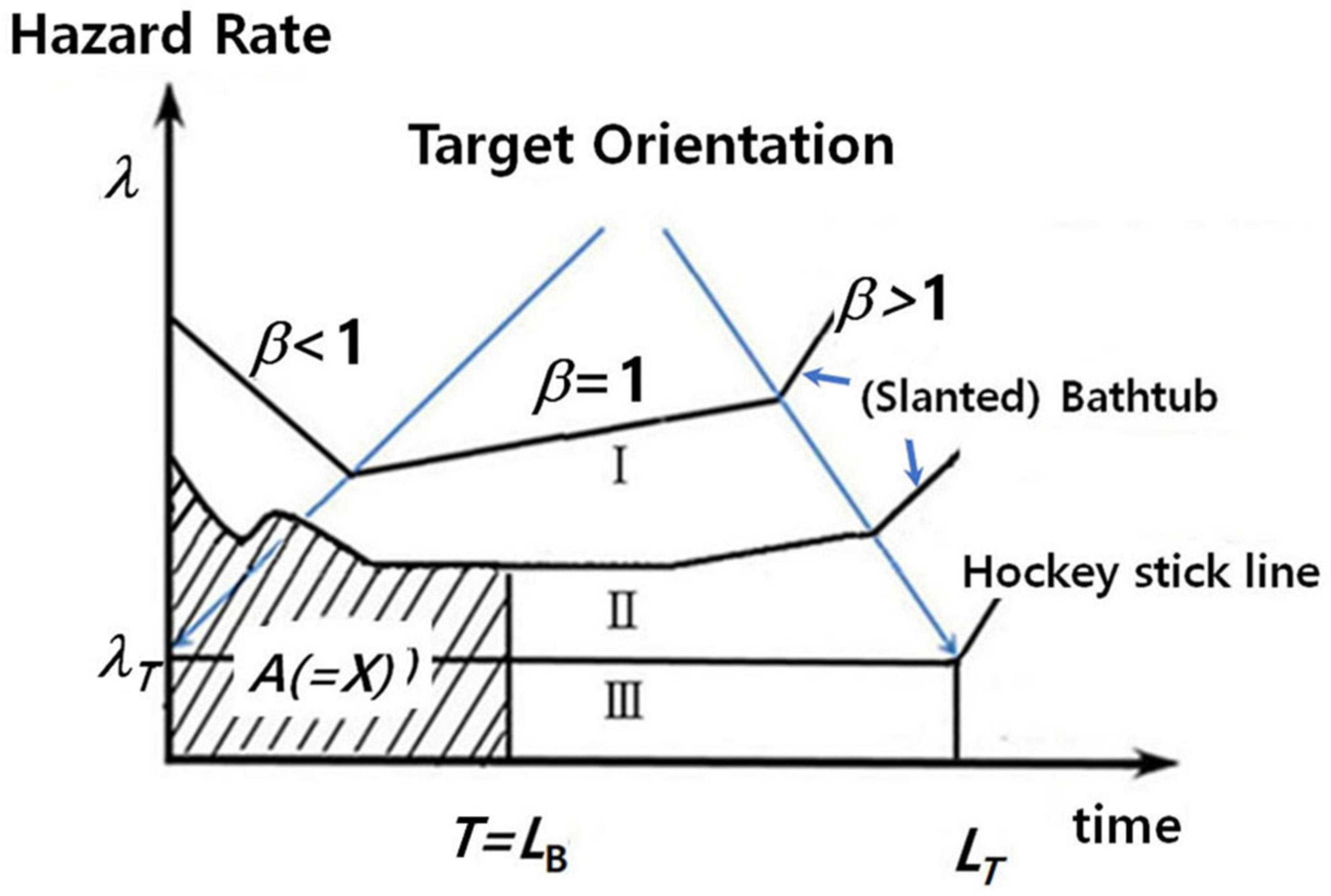
2.1. Meaning of BX Lifetime

A product operated by machinery utilizes generated power to achieve a desired motion by adapting an appropriate mechanism [30]. Forces are utilized to supply the movement of mechanisms in the system. This movement signifies that the system shall be subjected to repeated loading. In a mechanical product, fatigue failure occurs when there are structural imperfections such as notches, sharp edges, grooves, and slender surfaces in a component.
For instance, a refrigerator uses the heat pump cycle that consists of a condenser, capillary tube, evaporator, and compressor. In a heat exchanger, cooled air is produced to prevent the spoilage of food in the refrigerator and freezer sections. Figure 1 shows that a refrigerator covers some systems (or modules): the cupboard and door, shelves and boxes, compressor or motor, evaporator and condenser, water supply and ice-making apparatus, controller, and diverse parts. A domestic refrigerator includes as many as 2000 elements. It can be divided into up to 20 units (or 8~10 modules) holding 100 elements each.
If the objective of system life is presumed to have a B20 life 10 years, the lifetime objective of all units should have a B1 life 10 years. If we assume a new subsystem, named Module #3, has a design flaw with a shorter life, it will determine the life of the total refrigerator.
The BX lifetime, LB, could be explained as a quantity of lifetime that X percent of the population has been unsuccessful. This is expressed as ”BX life Y years”. If the lifetime of a part is B20 life 10 years, 20% of the concerned parts should not fail for ten years. In contrast, the reverse of the failure rate, the B60 life, denotes the mean time to failure (MTTF). The B60 life is not utilized for determining the product life because it is too long for 60% of the systems to fail. The BX lifetime is an acceptable indicator of system life.

2.2. Posing an Entire ALT Procedure

Reliability can be described exactly as the potential for a product to perform under a set of prescribed operational/environmental situations for a required period of time [31]. It is often demonstrated as the bathtub (Figure 2). This figure shows three curves. Each curve may be expressed in accordance with the shape parameter in the Weibull chart. In the 1st division, there is a declining rate of failure in the premature section of the system’s life (β < 1). In the 2nd division, there is a uniform rate of failure (β = 1) in the medium lifetime of the system, pursuing an exponential distribution. Finally, there is a growing rate of failure to the ending of the product life (β > 1), which follows a Weibull distribution.
The unreliability or accumulative distribution function (CDF),  F t o r   X = 1 R t , is expressed by
F t = P T < t
On the (slanted) bathtub in Figure 3, the failure rate, λ, shall be defined as:
λ t = f t / R t = d F t / d t R t = d 1 R t / d t R t = R t R t
where f is the density function.
If Equation (2) takes the integral, the life of X% accumulative failure, F(LB), at t = LB can be assessed. F(LB) is expressed as follows:
F t = λ t d t = R t R t d t = l n R t
Or   A o r   X = λ · L B = 0 L B λ t d t = l n R L B = l n 1 F F L B
As T1 is presumed to have the period of the 1st failure in the 2nd division of the (slanted) bathtub, reliability, R(t), is expressed as follows:
R t = P n o   f a i l u r e   i n   0 , t = m 0 e m 0 ! = e m = e λ t
where m is the parameter  m = λ t .
As the failure rate of a system mimics the features on the (slanted) bathtub (Stage Ⅰ or Ⅱ), it will be unsuccessful in the market. Due to design flaws, a great number of premature failures in the untimely part of the curve could spoil the brand name of the company with the product release. High failure rates in the initial product’s lifetime require warranty costs on the manufacturer, and the market share would be anticipated to be negatively affected. The company would be required to enhance the system by (1) removing unpredicted premature failures, (2) lessening (random) failures for its function time, and (3) enlarging the product life.
As a structural design is improved, the system lifetime of the product in the market should increase, and its failure rate should decrease. In this situation, the (slanted) bathtub might be altered to a curve with lower initial failure rates and a longer lifetime. Eventually, as the system is redesigned, the accumulative failure rate, F(t), should improve until the expected design life is met. The product’s bathtub shall be similar to the straight line (stage Ⅰ → Ⅲ) in Figure 2.
In Equation (5), the product reliability is simply expressed as the failure rate,  λ , and lifetime,  L B . Namely,
R L B = e λ L B 1 λ L B
This correlation in Equation (6) is adequate and less than just 20% of the cumulative failure rate [32].
For example, an ice-maker repetitively requires a straightforward mechanical operation: (1) water is provided to the flat and shallow container; (2) it then solidifies into ice by cooled air being blown over it; and (3) the ice is then harvested until the ice container is filled. The ice is retrieved by the consumer when they apply force on a lever that allows the cubed (or crushed) ice to be dispensed. During the process, an ice-maker is subjected to repeated stresses. Failed parts from the field are decisive for comprehending and pinpointing the repetitive usage methods of end-users and identifying structural imperfections in the structure. From the marketplace statistics, the real cause(s) of the troublesome auger motor, including the bearing, was identified. When setting the objective life, LB, by employing an ALT, the part functioned by machine shall be altered by pinpointing the controversial component and improving it (Figure 3).
Figure 3. Parameter description of the ice-maker (example).
Sustainability 15 07010 g003
From the market statistics—present lifetime and failure rate—the real cause(s) of the troublesome ice-maker failed from the end-user had been identified. To fulfill the desirable reliability from the objective lifetime, LB, and failure rate, λ, the possible design flaws of the component might be found and altered by utilizing an ALT.
To reach the target product life by the ALT, three subsystems (or modules) were classified: (1) a modified system, (2) a newly designed system, and (3) the same system. The ice-maker in a household refrigerator utilized in this test investigation was a system which had design defects that should be corrected. End-users had been demanding a replacement ice-maker when the original units had been failing prematurely. Through system D (Table 1) from the market, data had a failure rate of 0.20% per year and a B1 life of 5.0 years. To reply to end-user appeal, an objective life for the ice-maker was specified to have a B1 life 10 years.

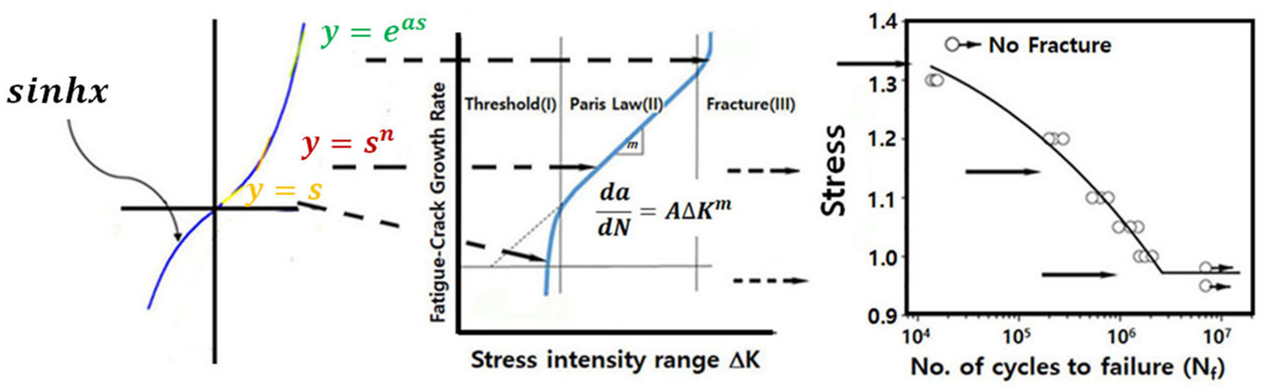
2.3. Deduction of Life-Stress Model

Because customers wanted to have (cubed or crushed) ice, an ice-maker was developed to be included in a household refrigerator. The major components in a household ice-maker are the geared auger motor, bucket case, helix upper dispenser, blade, etc. An auger motor has two or more gears working together by interlocking their teeth and revolving each other to produce torque and speed. As the motors are engaged, the geared trains lessen the speed of the augers and increase the torque. The auger motor operated by the alternating current (AC) grows the torque by gearbox to break it up at the end of an ice-maker. As a consumer pushes the lever with a cup on the dispenser, (cubed/crushed) ice flows to fill the cup. Consequently, the ice-maker shall be subjected to repeated stresses due to loading/unloading in the process of crushing ice. If there are structural flaws, such as an inadequate strength to withstand repeated loads, the ice-maker can be successful before satisfying its targeted life. That is, failure happens when the materials in the system parts are too fragile to withstand the exerted stress under environmental circumstances [33].
Reproducing the field failures by ALT, an engineer must understand and quantify the loading that is encountered by the ice-maker in the field before designing the system shape and materials to achieve the objective reliability of the system. Once optimally redesigned, the product might be anticipated to endure the minimum repeated loading in its expected life so that it may extend the targeted life. From the relation between load and lifetime, the (generalized) life-stress prototype that will integrate with geometry and material as the design solution should be derived, which can be described by the phenomena of void generation/transport from the level of quantum mechanics. Eventually, cracks and their propagation might be described by a sample size formulation (Figure 4).
The motivation for the ALT is to resolve how premature the anticipated failure mode might be pinpointed by mathematically employing the work for parametric modeling. That is why elevated tests need to be carried out. To depict the elevated testing time into actual usage time, it is necessary to arrange a straightforward failure expression and resolve the correct numerical method for the life type. The life-stress (LS) type, requiring quantifiable stresses and reaction factors, should be developed. Thus, it will express mechanical failure, such as structural fatigue. Fatigue on the surface of a structure can occur not only due to component stresses but also due to defects such as cracks.
d 2 ψ d x 2 + K 2 ψ = 0
where  K 2 = 8 π 2 m E h 2 , E is the (electron) energy, h is the Planck constant, and m is the electron mass.
The boundary conditions are as follows: (1)  ψ n  limited in the metal but decaying exponentially. The solution of Equation (7) shall be attained [34,35]:
ψ x = 2 a s i n n π a x   or   E n = n 2 h 2 8 m a 2   n > 0
where  ψ x + a = ψ x , a is the (periodic) interval, and n is the main quantum number.
The diffusion phenomena can be expressed (Table 2) [36,37]:
J = L D
where J is the diffusion flux, D is the driving force, and L is the transport constant.
In particular, when an electromagnetic force, ξ, is exerted, the metal impurities, caused by electronic movement, easily float to the right-hand as the junction magnitude energy is lowered. Expressing the solid-state diffusion of impurities of silicon in a semiconductor can be shortened: (1) electromigration-induced voiding; (2) build-up of chloride ions; and (3) trapping of electrons or holes. The transport diffusion process, J, might be defined as [38]:
J 1 = a C x a e x p q k T W 1 2 a ξ v
where  a C x a  is the density per unit area of electric particles located in the valley at  x a , and the exponential factor is the chance of a successful jump from the valley at  x a  to the valley at  x . Note the lowering of the barrier due to the electric field  ξ .
Similar formulas can be expressed for  J 1 J 2 , and  J 3 . As these are integrated to formulate the flux  J  at position  x , with the concentration  C x ± a  approximately by  C x ± a C / x , the flux  J  is
J = a 2 v e q w / k T c o s h q a ξ 2 k T C x + 2 a v e q w / k T C   s i n h q a ξ 2 k T
where C is the concentration quantity, q is the amount of accumulated electrical energy, ν is the jump frequency, a is the atomic intervening time, ξ is the exerted field, k is Boltzmann’s quantity, and T is the (absolute) temperature.
Unless the electric field is relatively small, i.e.,  ξ q a 2 k T , Equation (11) might be redefined as follows:
J = Φ x , t , T s i n h a ξ e x p Q k T
or
J = B   s i n h a ξ e x p Q k T
where Q is the energy and, Φ() and B are constants.
If Equation (13) captures a reverted formulation, the life-stress (LS) type shall be clarified as:
T F = A s i n h ( a S ) 1 e x p E a k T
For a prototype, Equation (14) is clarified as a general expression because the sine hyperbolic expression  s i n h a S 1  designating stress shall be exchanged into a power (or exponential) formulation. It then may outline most of the LS prototypes about some failure, such as fatigue in the system. It can be conveyed as follows: (1) first,  S 1  has a nearly straight line; (2) second,  S n  has what is viewed; and (3) third,  e a S 1  is largely developed (Figure 5).
Because ALT is frequently carried out in the span amidst stress, Equation (14) is expressed as:
T F = A S n e x p E a k T
where  n = l n T F l n S T .
For an expressed crack and structural form, Equation (15) can be redefined as
T F = B Δ K n e x p Q k T
where B is constant,  Δ K = Y S o r   Δ σ π a .
As the stress intensity component, ∆K, is exerted on a material, the crack will produce to a specific amount ∆a, which relies on the crack growth speed, ∆a/∆N, in component shapes such as crack tips such as grooves, slender areas, holes, etc. It therefore propagates to a risky magnitude. As loads are exerted until the targeted lifetime, LB or mission time, the stress raisers (or material) in a component can be discovered.
The stress of a product functioned by machinery is a complex quantity to formulate in a raised testing. Because the energy is clarified as the product of flow and effort, the stress comes from effort in an energy transport system [39]. Thus, Equation (15) or (16) can be stated as follows:
T F = A S n e x p E a k T = C e λ e x p E a k T
where C is constant.
The acceleration factor (AF) is clarified as the portion between the raised stress and typical functioning situation. From Equation (17), AF shall be modified to merge the effort idea:
A F = S 1 S 0 n E a k 1 T 0 1 T 1 = e 1 e 0 λ E a k 1 T 0 1 T 1

2.4. Obtaining of the Sample Size Formulation for ALT

To accomplish the desired assignment time of the ALT from the targeted BX life in the testing plan, expressed in Section 2.1 and Section 2.2, the sample size formulation integrated with AF in Section 2.3 might be derived. The Weibull distribution for system life is extensively employed because it is defined as an expression of the characteristic life, η, and shape parameter, β. Therefore, if the system keeps to the Weibull distribution, the accumulative failure rate, F(t), in Equation (1) is defined:
F t = 1 e t η β
where t is the (passed) time.
If Equation (19) takes the logarithm at  t = L B , it is
L B β = l n 1 x 1 η α β
where  x  is the accumulative failure rate until lifetime ( x = F / 100 ), and  η α β  is the characteristic life.
Failures on the Weibull distribution are divided into some classes—infant mortality, random failure, and wear-out failure—depending on shape parameter (see Figure 2). The Weibayes procedure is explained as a Weibull examination with an assigned shape parameter, which can be obtained from prior experience or test data. Mentioning on Weibayes, characteristic life,  η M L E , is attained from utilizing the maximum likelihood estimate (MLE):
η M L E β = i = 1 n t i β / r
where  t i  for each sample is testing time, and r is the failure numbers.
The confidence level is  100 1 α , so characteristic life,  η α , can be assessed as follows:
η α β = 2 r χ α 2 2 r + 2 · η M L E β = 2 χ α 2 2 r + 2 i = 1 n t i β
If Equation (22) is substituted into Equation (20), it is
L B β = l n 1 x 1 2 χ α 2 2 r + 2 i = 1 n t i β
As the whole reliability test is carried out with a limited sample number, the test scheme can be defined as:
n h β t i β n r h β
If Equation (24) is inserted into Equation (23), it is
L B β l n 1 x 1 2 χ α 2 2 r + 2 n r h β L B * β
If Equation (25) is reordered, the sample size expression is found as:
n χ α 2 2 r + 2 2 × 1 l n 1 x 1 × L B * h β   + r
As the 1st term  χ α 2 2 r + 2 2  in a 60% confidence level is approximated to (r + 1) and  l n 1 1 x  approximates to  x , Equation (26) is redefined as:
n r + 1 × 1 x × L B * h β
As AF in Equation (18) is replaced into the test time, h, Equation (27) shall be redefined:
n r + 1 × 1 x × L B * A F h a β
where Equation (28) will be clarified as n ~ (failed samples + 1)·(1/cumulative failure rate)·((objective life/(test time)) ^ β.
Equation (28) shall be affirmed as [1,40] and Appendix A. Namely, for  n r , the sample size shall be expressed as:
n = χ α 2 2 r + 2 2 m β l n R L 1 = χ α 2 2 r + 2 2 × 1 l n 1 F L 1 × L B h β
where  m h / L B .
If  r = 0 , the sample size can be indicated as:
n = l n 1 C L m β l n R L = l n 1 C L m β l n R L = l n 1 C L 1 m β l n R L 1 = l n α 1 m β l n R L 1 = χ α 2 2 2 × 1 l n 1 F L 1 × L B h β
where  2 l n α 1 = χ α 2 2  and CL is the confidence level.
If the objective of a product life–ice-maker is presumed to have a B1 life 10 years, the allocated test is computed for the assigned parts under raised circumstances. In executing parametric ALTs, the structural defects of a product operated by machinery will be found and altered to obtain the intended system life.

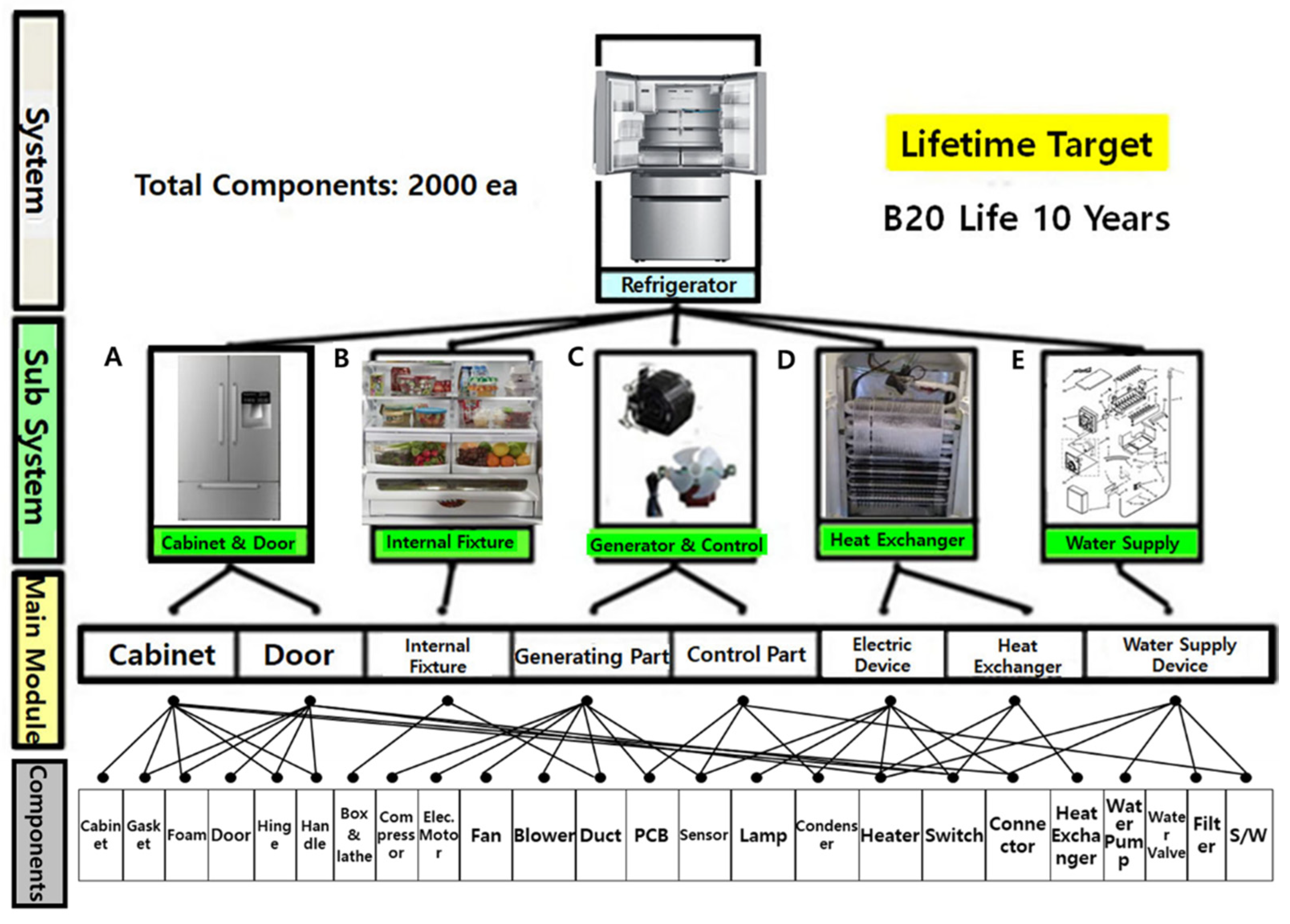
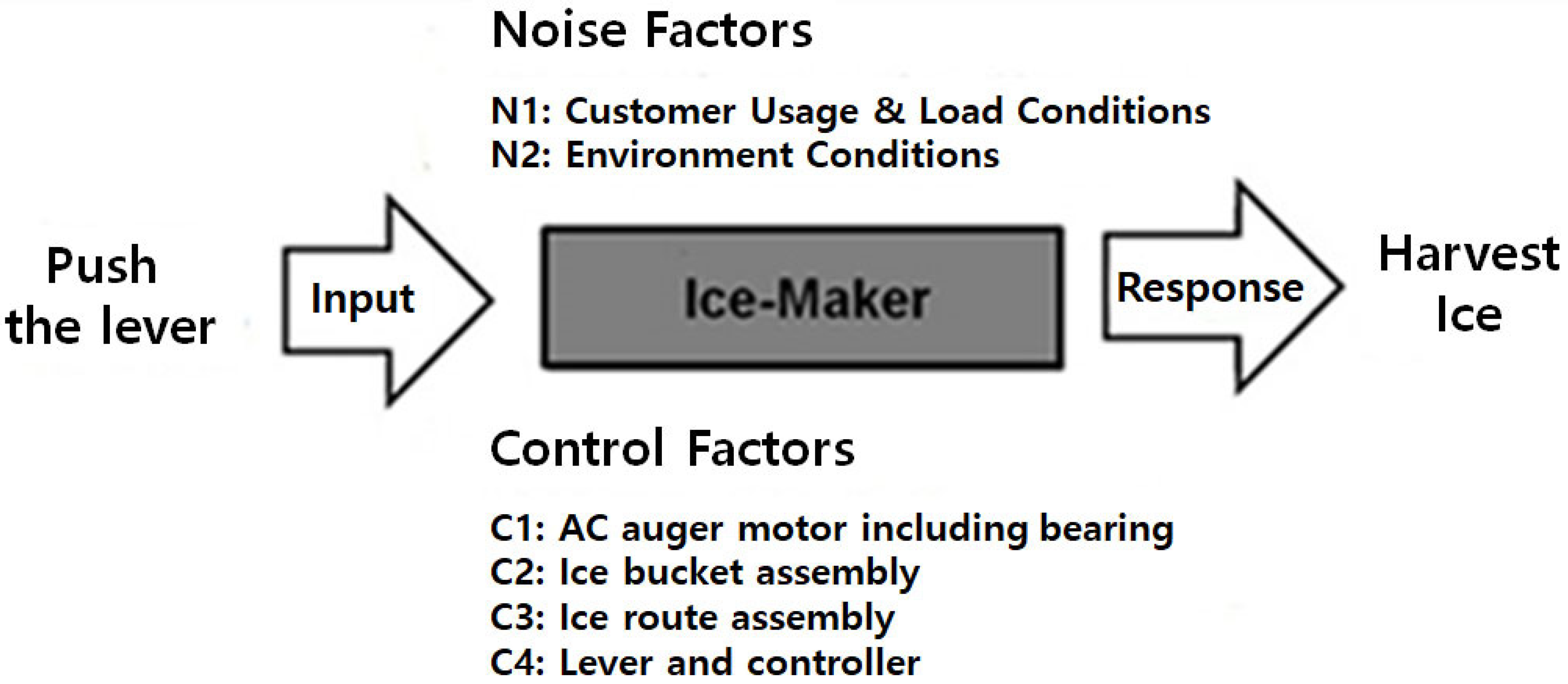
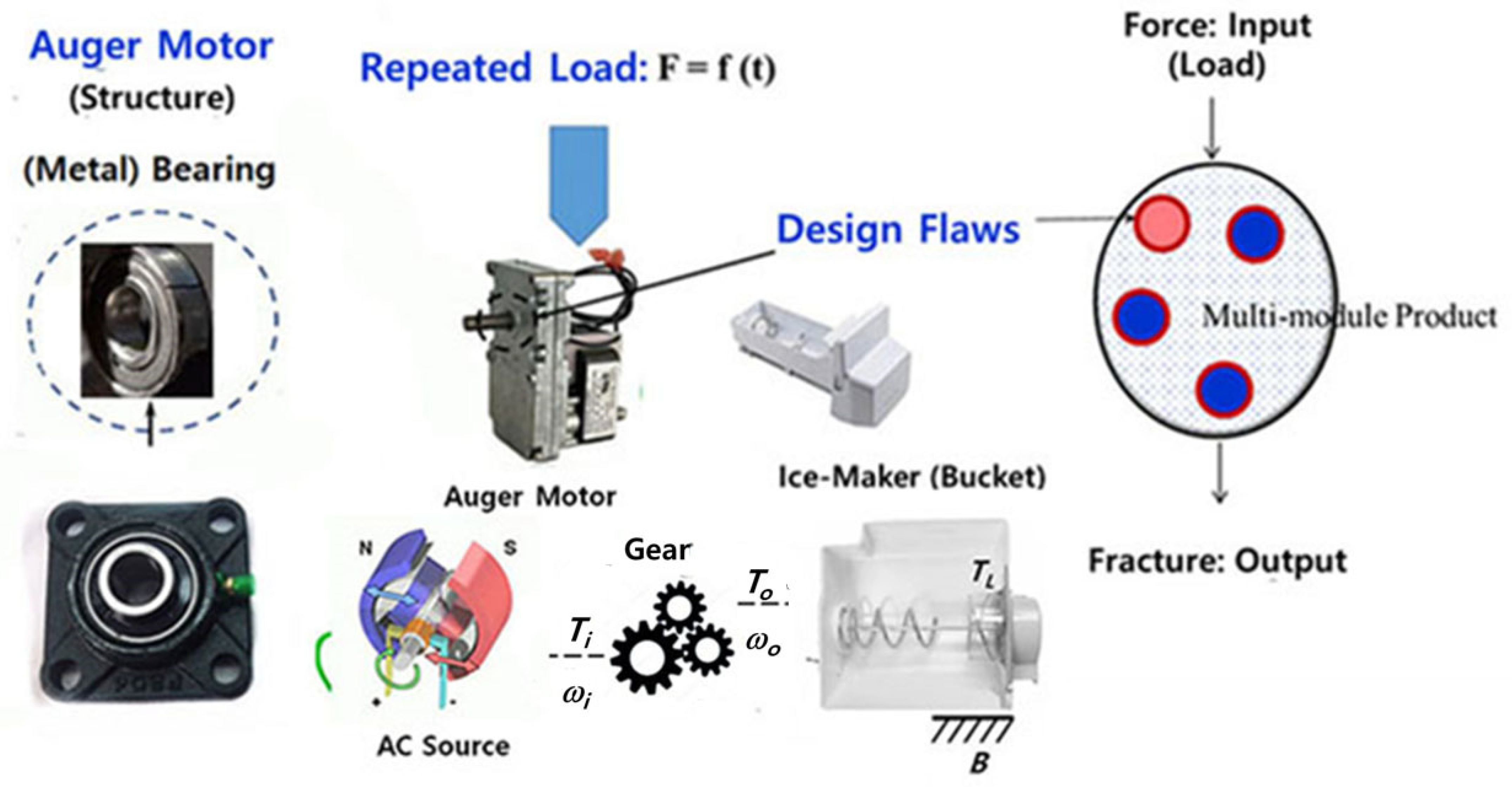
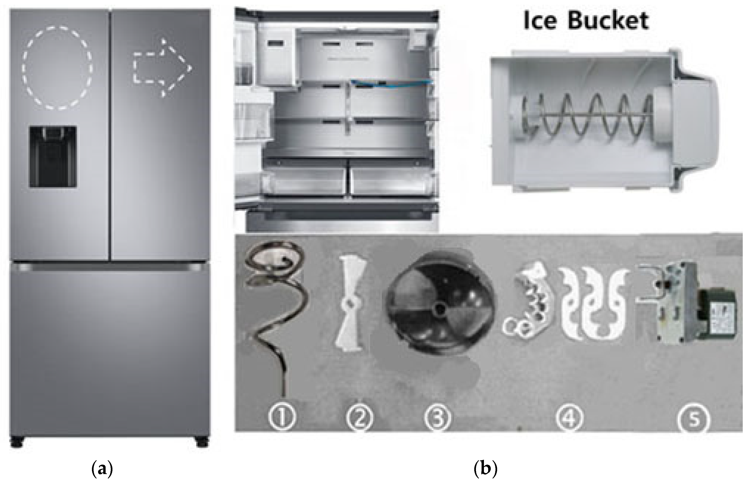
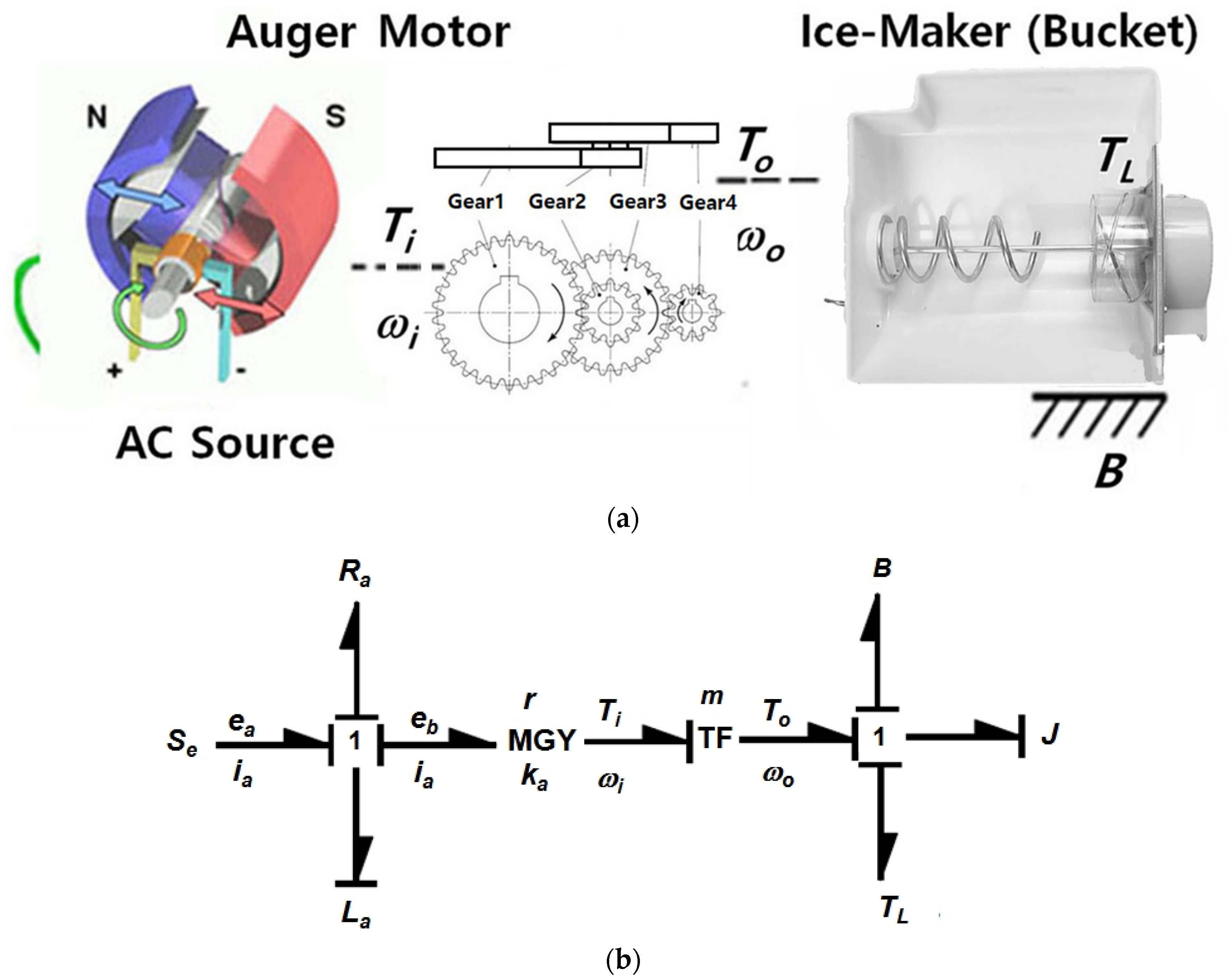
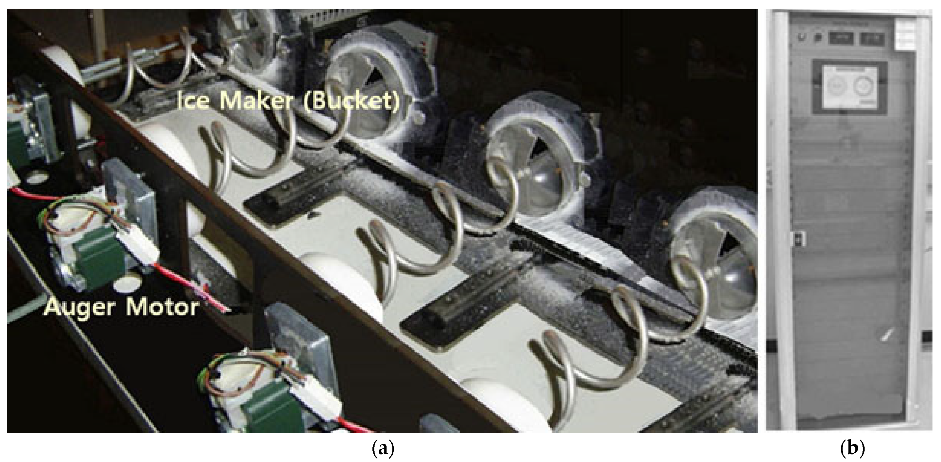
2.5. Case Investigation—Magnifying Life of an Ice-Maker Incorporating Auger Motor with a Bearing in a Household Refrigerator

Because customers want the convenience of (cubed or crushed) ice being distributed from a household refrigerator, an ice-making system was designed in a refrigerator. As a consumer utilizes a cup to apply force on the lever, ice is dispensed. The major parts include an auger motor with a geared system and bearings, helix upper dispenser, etc. These components must be designed for high-strength fatigue because of the repetitive stresses they are subjected to under normal consumer usage (Figure 6).
In ice-making, the parts undergo repeated mechanical loads and need to be strong enough to not fracture due to fatigue before the expected life. A household refrigerator in the United States is designed to harvest ice at a rate of 10 cubes per use and 200 cubes per day. Ice harvesting may also be affected by individual end-user usage patterns, such as ice usage, (tap) water pressure, notch positions in refrigerators, and the cycles of door opening. When set to the crushed mode, the ice-maker is repetitively subjected to (impact) loads in crushing ice. In the market, ice-makers, including auger motors, were unsuccessful under unidentified consumer usage in a refrigerator. Field statistics also showed that the ice-makers returned from the market had structural defects such as material problems (high carbon alloy steel with 1.30–1.65% chromium) under the typical freezing temperatures (below −20 °C) found in the refrigerator. For the customer, the ice-maker system experienced a sudden failure and no longer functioned. Engineers were required to determine the basic causes by a failure analysis (or laboratory tests) and then modify the ice-maker (Figure 7).
By utilizing a failure analysis (and laboratory tests) for failed market parts, under typical freezer temperatures (below −20 °C), a crack began in the outer ring of the bearing and propagated to the end. The system had to be redesigned. If there are structural defects—improper bearing material in the auger motor—where repeated loads are exerted in the freezer section, it will fail before its expected life. To reproduce the troublesome component(s) and modify them, a designer was required to perform the ALT for a product. It consisted of (1) a load inspection for the troublesome product (Section 2.5), (2) the measures of taking the feasible and actual usage of ALTs with modifications (Section 3), and (3) the appraisal of whether the life target of current structures (Section 3) had been accomplished.
To attain the differential equations which are made up of state variables for the parametric prototype, the bond graph in Figure 8 shall be settled as follows (Appendix B):
d i a / d t d ω / d t = R a / L a 0 m k a B / J i a ω + 1 / L a 0 e a + 1 1 / J T L
As the differential equation, Equation (31) finds the integral, the output,  y p , harvested by the ice-maker obtained as follows:
y p = 0 1 i a ω
From Equation (31), the lifetime of the ice-maker depends on the required torque to harvest the crushed ice. By altering the torque, the ALT can be performed. The life-stress prototype in Equation (17) is adjusted as
T F = A S n = A T L λ = A F c × R λ = B F c λ
where A and B are constants.
Thus, the AF in Equation (18) shall be defined as
A F = S 1 S 0 n = T 1 T 0 λ = F 1 × R F 0 × R λ = F 1 F 0 λ
The ALT from Equation (34) can be carried out until the mission time which satisfies the life target—B1 life 10 years—is attained.
The surrounding conditions of an ice-maker in a household refrigerator can change and range from −15 to −30 °C with humidity ranging from 0% to 20%. Depending on the end-user use operating conditions, an ice-maker is expected to operate from three to eighteen cycles per day. For the highest utilization for ten years, the ice-maker can be expected to experience 65,700 life cycles.
The stress amount for the ALT was determined using the permitted utilization range provided from the auger motor manufacturers in bench-marked statistics. Step-stress lifetime testing was applied under the usage conditions for several elevated loads including 0.8 kN-cm, 1.0 kN-cm, and 1.47 kN-cm [41]. These torques were different from the expected applied torque of 0.69 kN-cm in the field. With the higher torques, the failure time of an auger motor at specific stress quantities could be expected to be faster than failures in the field.
Engineering statistics from the auger motor company showed that the common torque was 0.69 kN-cm and the maximum torque was 1.47 kN-cm. If the cumulative damage factor, λ, was 2, AF in Equation (34) was almost five.
For a life objective, a B1 life 10 years, the number of assignment cycles for ten components (attained by employing Equation (28)) was 42,000 cycles if the shape parameter was assumed to be 2.0. The ALT was set to assure a life objective if it was unsuccessful for 42,000 cycles. Figure 9 shows the test equipment of an ALT for replicating the failed ice-maker, involving the auger motor in the market. Figure 10 shows the duty cycles applied by the crushing torque TL.
The evaluated life LB in every ALT stage is expressed as
L B β x n h a A F β r + 1
where ha is the real testing time.
Let x = λ LB. The approximated failure rate λ of the selected parts is expressed as
λ 1 L B r + 1 L B β n h a A F β
In every ALT stage, by measuring the approximated LB life and failure rate λ, the reliability of the system design operated by machinery can be secured.

3. Results and Discussion

From Equation (33), it can be seen that the life of an ice-maker relies on the exerted torque TL. To rapidly identify the failure time of an ice-maker, the torque was enhanced from Equation (34). Putting a scale of stress level due to the applied load by the step-stress life tests, the failure time(s) were investigated at successive stress quantities: 0.8 kN-cm, 1.0 kN-cm, and 1.47 kN-cm (torque for ALT). For 0.8 kN-cm, the ice-maker terminated at approximately 11,000 cycles. For 1.0 kN-cm, the ice-maker terminated at approximately 9000 cycles and 13,000 cycles. For 1.47 kN-cm, the ice-maker terminated at approximately 5000 cycles and 8000 cycles. Therefore, the stress quantity of 1.47 kN-cm was set for the ALT as it had a comparatively excellent linearity in the Weibull chart, compared to the dissimilar stress quantities.
In the 1st ALT, the fractured bearings of the auger motor occurred at approximately 6500 cycles and 6900 cycles from the failed ice-makers that were disassembled. Figure 11 shows a photograph contrasting with the product returned from the market and that from the 1st ALT. By employing scanning electron microscopy (SEM), the fractures in the images occurred in the outer ring. The fractured surface on the cross-section had an intergranular (IG) crack and fatigue due to repeated impact under severe environmental conditions.
Because failed samples were indistinguishable in shape through the ALT, we might reproduce the fractured outer ring of a bearing in the market. There was a material design defect—AISI 52100 Alloy Steel with 1.30–1.60% chromium—which could not endure the stresses due to the repetitive torques at the freezing temperatures (−20 °C below) in the refrigerator. As the bearing and shaft in an ice-maker repetitively struck together, they began to crack and ultimately fractured because the material (AISI 52100 Alloy Steel) was too brittle under these circumstances: repeated impacts and severe cold temperature (−20 °C ↓). Figure 12 shows the visual inspection of the parametric ALT outcomes and field data in the Weibull chart. The shape parameter in the 1st ALT which relied on loading circumstances was estimated to be 2.0. For the test, it was affirmed to be 4.38 in the Weibull chart.
To withstand the repetitive impact torque, the material of the troublesome bearing in an auger motor was modified from AISI 52100 Alloy Steel with 1.30–1.65% chromium to the lubricated sliding bearing with sintered and hardened steel (FLC 4608-110HT). The quantities of AF and β in Equation (34) and Figure 12 were confirmed to be 5.0 and 4.1, respectively. Based on the test statistics, because the life target of a new sample was a B1 life ten years, the test time recomputed in Equation (29) for the ten samples was 23,400 cycles, which would be the statement of the parametric ALT.
In the 2nd ALT, at 10,000 cycles and 12,000 cycles, the fracture of the helix upper dispenser (polycarbonates (PC)) happened in the exposure area of the blade dispenser (Figure 13). To understand the basic cause of the failed product, it was examined. It was discovered that there was a constructional flaw—the weld line between the helix upper dispenser and the blade dispenser—that had countless microvoids generated in the plastic injection procedure. As the blade dispenser (stainless-steel) stroked the helix upper dispenser (PC) under extreme freezing circumstances, it began to crack and eventually fractured at the weld line (Figure 13b). As an alternative, a strengthened rib of the helix was thickened after the plastic injection procedure was altered. Then, a finite element analysis (FEA), integrated with the ALT, was carried out. As the helix upper dispenser was fastened against the barrier, a simple impact torque (1.47 kN-cm), as shown in Figure 8, was applied. Utilizing materials and processing circumstances close to those of the helix upper dispenser, the constitutive material properties such as PC (helix upper dispenser) were discovered. As a consequence, the stress of the parts by the FEA inspection was lessened from 45.0 kPa to 20.0 kPa (Figure 14) [42,43].
As the material of the bearing in an auger motor was modified and the strengthened rib of the helix upper dispenser was thickened, the lifetime of an ice-maker was expanded. However, as the 23,400 mission time in the 2nd ALT was not yet achieved, the 3rd ALT was performed to assure the structural alternation of an ice-maker.
There was no problem in the 3rd ALT until 60,000 cycles. Over the rounds of three ALTs with alternations, the ice-maker was assured to have B1 life 10 years with an accumulated failure rate of 1% from Equations (35) and (36) when the real cycles,   h a = 60,000   cycles ; in inserting in lifetime target, x = 0.01; sample size, n = 10; accelerated factor, AF = 5.0; shape parameter,  β = 4.10 ; and failure number, r = 0.0. Table 3 shows a curtailed outcome of the parametric ALTs.

4. Summary

To improve the lifetime of a refrigerator with an ice-maker, a reliability structured method was employed. The method was used to improve the ice-maker augur motor and bearing. The method involved a life-stress prototype by a quantum-transported procedure and a sample size formulation. It covered the following: (1) the product BX life formed the ALT strategy, (2) ALTs with alterations, and (3) resolving if the product design obtained the targeted time. The ice-maker was examined as a case investigation.
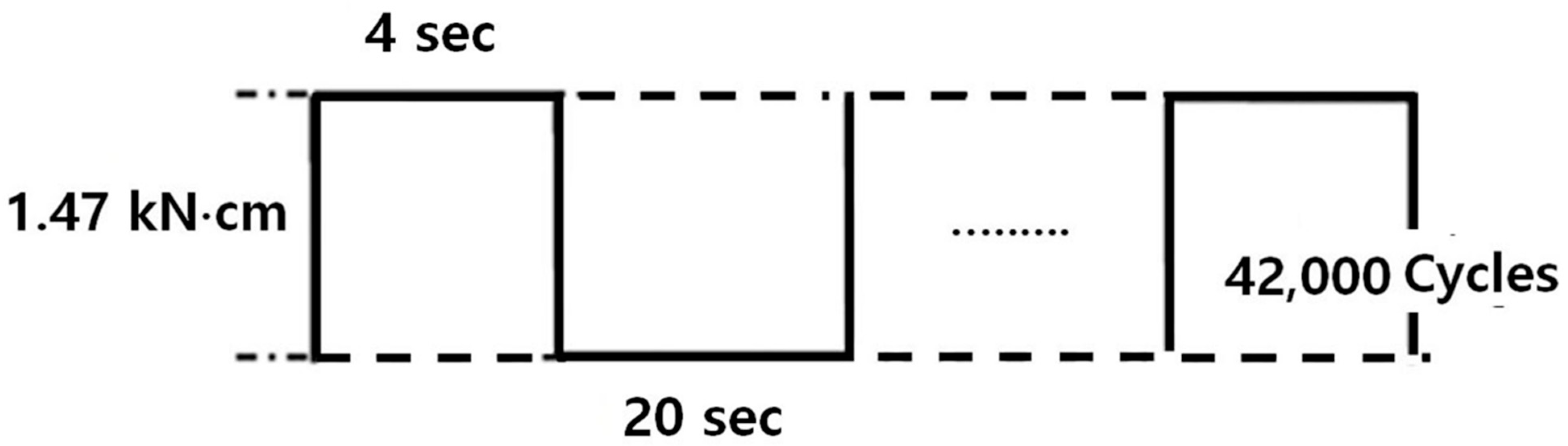
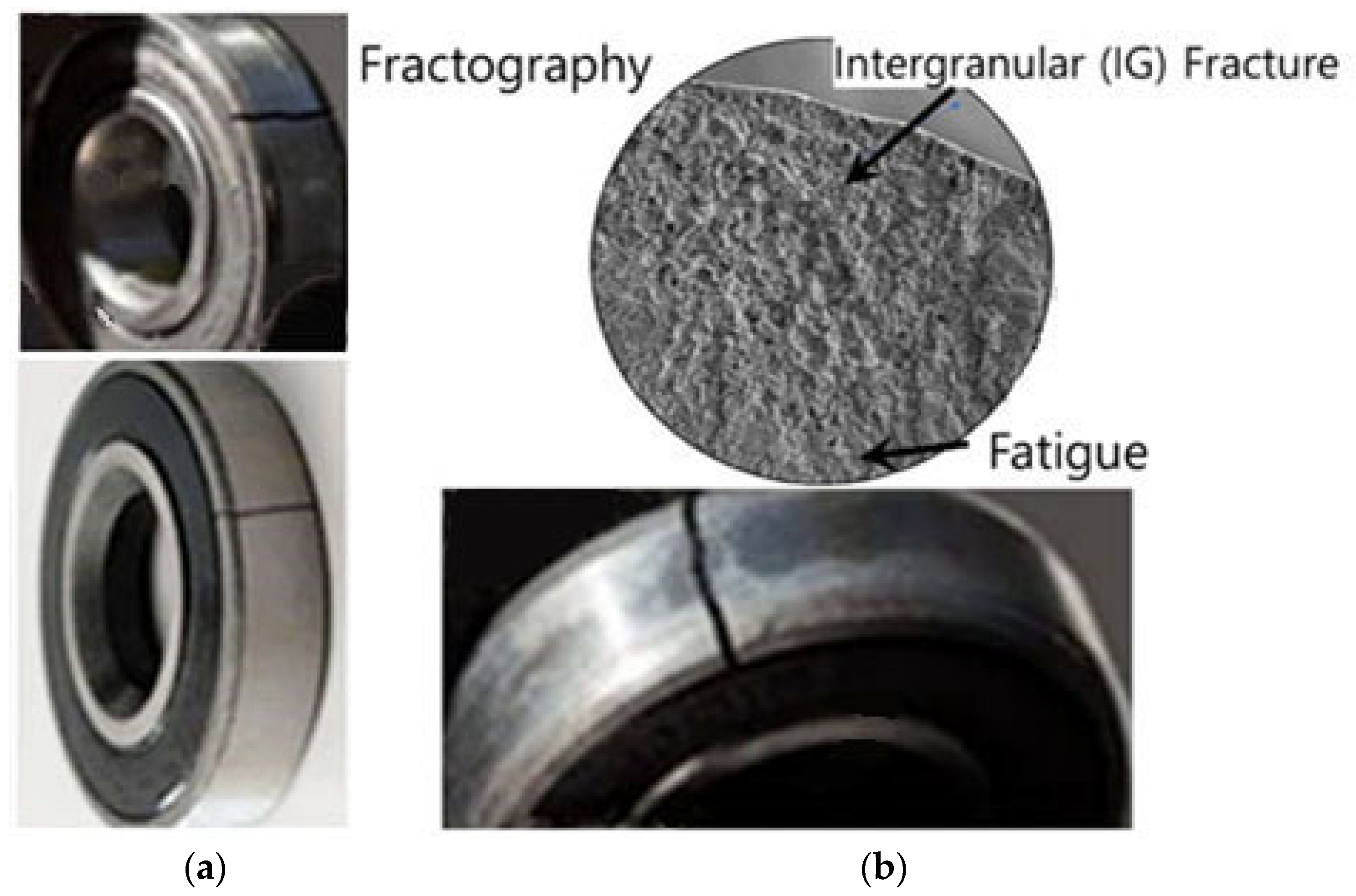
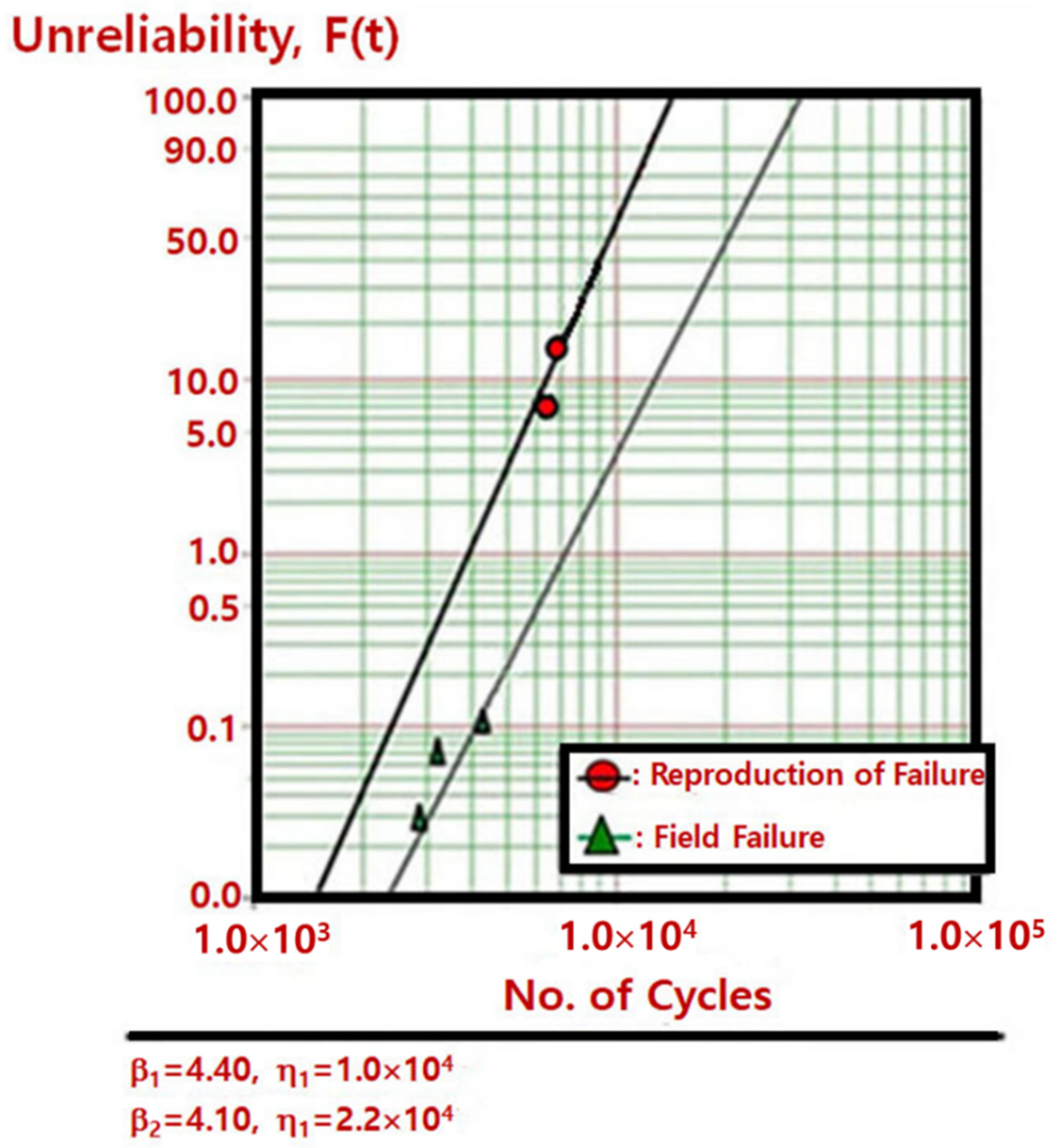
  • In the 1st ALT, the auger motor in an ice-maker terminated near 6600 cycles and 6900 cycles as exerted for torque −1.47 kN-cm under the freezing temperatures (−20 °C below) in the refrigerator. After disassembling the troublesome samples, we found the fractured outer ring of the bearing in an auger motor. As an action plan, the bearing matter in an ice-maker was altered from AISI 52100 Alloy Steel with 1.30–1.60% chromium to lubricated sliding bearing with sintered and hardened steel (FLC 4608-110HT).
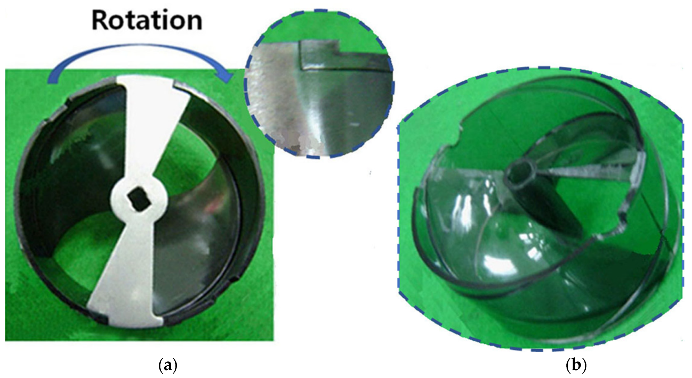
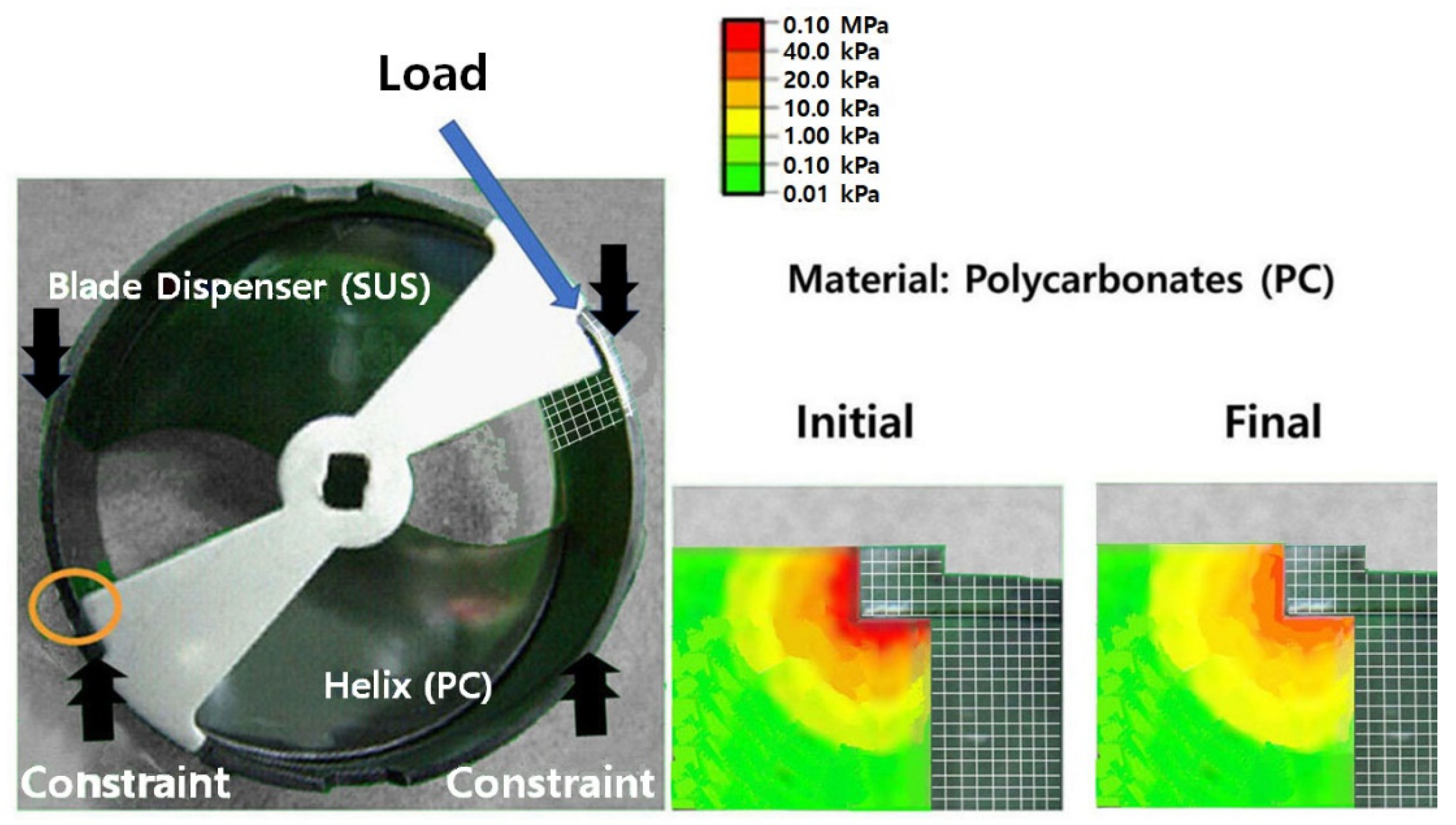
  • In the 2nd ALT, the helix (polycarbonates) at 10,000 cycles and 12,000 cycles was fractured because the ice-maker had insufficient fatigue strength for repetitive stress in the freezer department. As an alternative, a reinforced rib of the helix was thickened after the plastic injection procedure was modified.
  • In the 3rd ALT, no problems were found. The ice-maker, involving an auger motor, will satisfy the life objective of B1 life 10 years. Inspecting controversial field parts and carrying out ALTs with modifications could grow the life of an ice-maker, involving an auger motor with a bearing.
  • By identifying and understanding the design problems of products that failed in the market, it was possible to carry out parametric ALTs with system modifications. When reproducing the market failures, the design defects can be recognized and altered. Ultimately, we approximated whether the system reached the life targets. In the process, the life-stress (LS) type and sample size were also utilized.

5. Conclusions

As design flaws are identified and corrected, this procedure with reliability quantitative (RQ) specifications will help improve sustainability and fulfill “zero waste” from poorly designed products with regard to the development of new products in the field. It has been relevant to different products operated by machinery such as agricultural machines, construction machines, airplanes, automobiles, etc. Engineers also are required to grasp why multimodule systems fail in their life. Namely, if there are structural defects where it is repeatedly subjected to loading in its working, the product shall be unsuccessful during its expected life. Preventing the fabrication of troublesome material (AISI 52100 Alloy Steel) in a mechanical system will help transform the lifestyle by properly utilizing a newly developed material in the agroindustry for the circular economy and preventing influencing the environmental change worldwide. Furthermore, customers will use a product of good quality and prevent generating futile waste. Moreover, this innovative and computational study will enhance the individual lifestyle in economics and permit forecasting the assessment of global transformation and evolution associated with sustainability.

Author Contributions

S.W. carried out the idea development, method, investigation, and experiment, and wrote the manuscript. D.L.O. edited the original documents and provided comments on the methods. Y.M.H. and G.M. altered the draft. All authors have read and agreed to the published version of the manuscript.

Funding

This research received no external funding.

Institutional Review Board Statement

Not applicable.

Informed Consent Statement

Not applicable.

Data Availability Statement

The data utilized in this study may be acquired on demand from the corresponding author.

Conflicts of Interest

The authors declare no conflict of interest.

Abbreviations

ALTAccelerated life testing
BXTime which is an accumulated failure rate of X%
CDFCumulative distribution function
DDriving force
FUnreliability
JDiffusion flux
LTransport quantity
LSLife-stress (LS) model
TFTime to failure
MTTFMean time to failure
RReliability

Nomenclature

EaActivation energy, eV
eEffort
ebCounterelectromotive force
efField voltage, V
fFlow
FcIce-crushing force, kN
F(t)Unreliability
hTesting cycle
h*Nondimensional testing time,  h * = h / L B 1  
ifField current, A
JMomentum of inertia, kg m2
kBoltzmann’s quantity, 8.62 × 10⁻⁵ eV/deg
LBObjective BX lifetime and x = 0.01 X, on the condition that x ≤ 0.2
mGear proportion
MGYGyrator in causal forms
nSample number
QEntire number of dopants per unit area
RRatio for minimum stress to greatest stress in stress cycle
rFailed numbers
rCoefficient of gyrator
SStress
TTemperature, K
tiTest time for each sample
TLIce-crushing torque in bucket, kN cm
XAccumulated failure rate, %
xx = 0.01 X, on condition that x ≤ 0.2
Greek symbols
ξElectrical field exerted
ηCharacteristic life
λCumulative damage quantity in Palmgren–Miner’s rule
χ2Chi-square distribution
αConfidence level
ωAngular velocity in ice bucket, rad/s
Superscripts
βShape parameter on the Weibull chart
nStress dependence,  n = l n ( T f ) l n ( S ) T  
Subscripts
0Normal stress circumstances
1Elevated stress circumstances

Appendix A. Derivation of Sample Size

To achieve the desired assignment cycles of ALT from the targeted BX lifetime in the testing scheme, the sample size formulation integrated with AF in Section 2.3 might be derived.
Each testing time, the Bernoulli test has one of the pair yields, such as failure or success. The accumulative probability, which keeps to a binomial distribution, is defined as follows:
L p = r = 0 c n r p r 1 p n r α
where n is the sample amount and c is the presumed unsuccessful amount.
If chance p is minute and n is large enough, Equation (A1), which pursues a Poisson distribution, will be redefined:
L n p = r = 0 c 1 r ! n p r e n p = r = 0 c 1 r ! m r e m α
where  m = parameter = n p .
As the p amount is α from Equation (A2), parameter m pursues the chi-square distribution,  χ α 2 (). That is,
m = n p ~ χ α 2 2 r + 2 2
The Weibull distribution for system lifetime is extensively employed because it is defined as an expression of the characteristic life, η, and shape parameter, β. Therefore, if the system keeps to the Weibull distribution, the accumulative failure rate, F(t), in Equation (1) is defined as
F t = 1 e t η β
where t is the (passed) time.
In the event of unreliability,  p = F t , and reliability,  1 p = R t , Equation (A4) shall be placed into Equation (A1). That is,
L p = r = 0 c n r 1 e t η β r e t η β n r α
Because  e t η β 1 t η β , Equation (A5) can be closed as follows:
L p r = 0 c 1 r ! t η β r 1 t η β n r α
As Equations (A2) and (A6) have a close shape, the characteristic life with a confidence level of 100 (1 − α) may be clarified:
m = n p = n t η β ~ χ α 2 2 r + 2 2   o r   η α β = 2 χ α 2 2 r + 2 n t β  
At BX life, LB, in Equation (A4), test cycles, t, becomes h.
L B β x η α β = x 2 χ α 2 2 r + 2 n t β = x 2 χ α 2 2 r + 2 n h β L B * β   for   x   0.2
where x = 0.01F(t).
If Equation (A8) is reordered, the sample size expression is found as:
n χ α 2 2 r + 2 2 × 1 x × L B * h β
As the 1st term  χ α 2 2 r + 2 2  in a 60% confidence level is approximated to (r + 1), Equation (A9) is redefined as:
n r + 1 × 1 x × L B * h β

Appendix B. Derivation of Governing Equation

To attain the differential equations that are made up of state variables for the parametric prototype, the bond graph in Figure 8 shall be settled at each node:
d f × E 2 / d t = 1 / L a × e E 2
d f M 2 / d t = 1 / J × e M 2
where La is the electromagnetic inductance.
The junction from Equation (A11) is
e E 2 = e a e E 3
e E 3 = R a × f E 3
where ea is the exerted voltage and Ra is the (electromagnetic) resistance.
The junction from Equation (A12) is
e M 2 = e M 1 e M 3
e M 1 = K a × i T P u l s e
e M 3 = B × f M 3
where B is the viscous friction constant, and ka is the constant of the counterelectromotive force.
Because  f M 1 = f M 2 = f M 3 = ω  and  i = f E 1 = f E 2 = f E 3 = i a  from Equations (A13) and (A14),
e E 2 = e a R a × f E 3
f E 2 = f E 3 = i a
If Equations (A18) and (A19) are substituted into Equation (A11), then
d i a / d t = 1 / L a × e a R a × i a
From Equations (A15)–(A17), we can attain
e M 2 = K a × i T L B × f M 3
i = i a
f M 3 = f M 2 = ω
If Equations (A21)–(A23) are substituted into (A12), then
d ω / d t = 1 / J × K a × i T L B × ω
From Equations (A20) and (A24), the state equations can be attained as follows:
d i a / d t d ω / d t = R a / L a 0 m k a B / J i a ω + 1 / L a 0 e a + 1 1 / J T L
As the differential equation in Equation (A25) finds the integral, the output,  y p , harvested by the ice-maker is obtained as follows:
y p = 0 1 i a ω

References

  1. Woo, S.; Pecht, M.; O’Neal, D. Reliability design and case study of the domestic compressor subjected to repetitive internal stresses. Reliab. Eng. Syst. Saf. 2019, 193, 106604. [Google Scholar] [CrossRef]
  2. Magaziner, I.C.; Patinkin, M. Cold competition: GE wages the refrigerator war. Harv. Bus. Rev. 1989, 89, 114–124. [Google Scholar]
  3. Bigg, G.; Billings, S. The iceberg risk in the Titanic year of 1912: Was it exceptional? Significance 2014, 11, 6–10. [Google Scholar] [CrossRef]
  4. Rogers, W.P.; Armstrong, N.A.; Acheson, D.C.; Covert, E.E.; Feynman, R.P.; Hotz, R.B.; Kutyna, D.J.; Ride, S.K.; Rummel, R.W.; Sutter, J.F.; et al. Report of the Presidential Commission on the Space Shuttle Challenger Accident; NASA: Washington, DC, USA, 1986.
  5. ASTM International. Failures of Rolling-Element Bearings. In Metals Handbook, 9th ed.; Volume 11 Failure Analysis and Prevention; ASTM International: West Conshohocken, PA, USA, 1990; p. 508. [Google Scholar]
  6. DVB Bank SE Aviation Research (AR). An Overview of Commercial Jet Aircraft 2013; DVB Bank SE Aviation Research (AR): Schiphol, The Netherlands, 2014; p. 20. [Google Scholar]
  7. Woo, S.; O’Neal, D.L. Reliability Design of Mechanical Systems Such as Compressor Subjected to Repetitive Stresses. Metals 2021, 11, 1261. [Google Scholar] [CrossRef]
  8. Woo, S.; O’Neal, D.L.; Matvienko, Y.G.; Mebrahtu, G. Enhancing the Fatigue of Mechanical Systems Such as Dispensers Entrenched on Generalized Life-Stress Models and Sample Sizes. Appl. Sci. 2023, 13, 1358. [Google Scholar] [CrossRef]
  9. Wang, L.; Li, Y. Boundary for aviation bearing accelerated life test based on quasi-dynamic analysis. Tribol. Int. 2017, 116, 414–421. [Google Scholar] [CrossRef]
  10. Duga, J.J.; Fisher, W.H.; Buxaum, R.W.; Rosenfield, A.R.; Buhr, A.R.; Honton, E.J.; McMillan, S.C. The Economic Effects of Fracture in the United States; Final Report; Available as NBS Special Publication 647-2; Battelle Laboratories: Columbus, OH, USA, 1982. [Google Scholar]
  11. Gope, P.C.; Mahar, C.S. Evaluation of fatigue damage parameters for Ni-based super alloys Inconel 825 steel notched specimen using stochastic approach. Fatigue Fract. Eng. Mater. Struct. 2020, 44, 427–443. [Google Scholar] [CrossRef]
  12. Sola, J.F.; Kelton, R.; Meletis, E.I.; Huang, H. Predicting crack initiation site in polycrystalline nickel through surface topography changes. Int. J. Fatigue 2019, 124, 70–81. [Google Scholar] [CrossRef]
  13. Campbell, F.C. (Ed.) Fatigue. In Elements of Metallurgy and Engineering Alloys; ASM International: Materials Park, OH, USA, 2008. [Google Scholar]
  14. Chowdhury, S.; Taguchi, S. Robust Optimization: World’s Best Practices for Developing Winning Vehicles, 1st ed.; John Wiley and Son: Hoboken, NJ, USA, 2016. [Google Scholar]
  15. Montgomery, D. Design and Analysis of Experiments, 10th ed.; John Wiley and Son: Hoboken, NJ, USA, 2020. [Google Scholar]
  16. Elishakoff, I. Stepan Prokofievich Timoshenko, in Encyclopedia of Continuum Mechanics; Altenbach, H., Öchsner, A., Eds.; Springer: Berlin/Heidelberg, Germany, 2020; pp. 2552–2555. [Google Scholar]
  17. Weingart, R.G.; Stephen, P. Timoshenko: Father of Engineering Mechanics in the U.S. Struct. Mag. 2007, 7, 2–3. [Google Scholar]
  18. Goodno, B.J.; Gere, J.M. Mechanics of Materials, 9th ed.; Cengage Learning, Inc.: Boston, MA, USA, 2017. [Google Scholar]
  19. Anderson, T.L. Fracture Mechanics—Fundamentals and Applications, 3rd ed.; CRC: Boca Raton, FL, USA, 2017. [Google Scholar]
  20. ASTM E606/E606; Standard Test Method for Strain-Controlled Fatigue Testing. ASTM International: West Conshohocken, PA, USA, 2019.
  21. ASTM E399; Standard Test Method for Linear-Elastic Plane-Strain Fracture Toughness of Metallic Materials. ASTM International: West Conshohocken, PA, USA, 2020.
  22. ASTM E647; Standard Test Method for Measurement of Fatigue Crack Growth Rates. ASTM International: West Conshohocken, PA, USA, 2015.
  23. ASTM E739-10; Standard Practice for Statistical Analysis of Linear or Linearized Stress-Life (S–N) and Strain-Life (ε-N) Fatigue Data. ASTM International: West Conshohocken, PA, USA, 2015.
  24. Braco, R.; Prates, P.; Costa, J.D.M.; Berto, F. New methodology of fatigue life evaluation for multiaxially loaded notched components based on two uniaxial strain-controlled tests. Int. J. Fatigue 2018, 111, 308–320. [Google Scholar] [CrossRef]
  25. McPherson, J. Accelerated Testing, Electronic Materials Handbook; Volume 1: Packaging; ASM International Publishing: Materials Park, OH, USA, 1989. [Google Scholar]
  26. McPherson, J. Reliability Physics and Engineering: Time-to-Failure Modeling; Springer: New York, NY, USA, 2010. [Google Scholar]
  27. Reddy, J.N. An Introduction to the Finite Element Method, 4th ed.; McGraw-Hill: New York, NY, USA, 2020. [Google Scholar]
  28. Matsuishi, M.; Endo, T. Fatigue of Metals Subjected to Varying Stress. Jpn. Soc. Mech. Eng. 1968. Available online: https://www.semanticscholar.org/paper/Fatigue-of-metals-subjected-to-varying-stress-Matsuichi-Endo/467c88ec1feaa61400ab05fbe8b9f69046e59260 (accessed on 1 February 2023).
  29. Palmgren, A.G. Die Lebensdauer von Kugellagern. Z. Ver. Dtsch. Ing. 1924, 68, 339–341. [Google Scholar]
  30. Cengel, Y.; Boles, M.; Kanoglu, M. Thermodynamics: An Engineering Approach, 9th ed.; McGraw-Hill: New York, NY, USA, 2018. [Google Scholar]
  31. IEEE STD 610.12-1990; IEEE Standard Glossary of Software Engineering Terminology. Standards Coordinating Committee of the Computer Society of IEEE: Piscataway, NJ, USA, 2002; (REAFFIRMED SEPTEMBER 2002). Available online: https://ieeexplore.ieee.org/document/159342 (accessed on 31 December 2020).
  32. Kreyszig, E. Advanced Engineering Mathematics, 10th ed.; John Wiley and Son: Hoboken, NJ, USA, 2011; p. 683. [Google Scholar]
  33. Evans, J.W.; Evans, J.Y. Product Integrity and Reliability in Design; Springer: New York, NY, USA, 2001; p. 7. [Google Scholar]
  34. Kroemer, H. A proposed class of hetero-junction injection lasers. Proc. IEEE 1963, 51, 1782–1783. [Google Scholar] [CrossRef]
  35. Simon, S.H. The Oxford Solid State Basics; Oxford University Press: Oxford, UK, 2017. [Google Scholar]
  36. Bird, R.B.; Stewart, W.E.; Lightfoot, E.N. Transport Phenomena, 2nd ed.; John Wiley and Son: Hoboken, NJ, USA, 2006. [Google Scholar]
  37. Plawsky, J.L. Transport Phenomena Fundamentals, 4th ed.; CRC Press: Boca Raton, FL, USA, 2019. [Google Scholar]
  38. Grove, A. Physics and Technology of Semiconductor Device, 1st ed.; Wiley International Edition: New York, NY, USA, 1967; p. 37. [Google Scholar]
  39. Karnopp, D.C.; Margolis, D.L.; Rosenberg, R.C. System Dynamics: Modeling, Simulation, and Control of Mechatronic Systems, 6th ed.; John Wiley & Sons: New York, NY, USA, 2012. [Google Scholar]
  40. Wasserman, G. Reliability Verification, Testing, and Analysis in Engineering Design; Marcel Dekker: New York, NY, USA, 2003; p. 228. [Google Scholar]
  41. Tang, L.C. Multiple-steps step-stress accelerated life tests: A model and its spreadsheet analysis. Int. J. Mater. Prod. Technol. 2004, 21, 423–434. [Google Scholar] [CrossRef]
  42. El-Azeem, S.O.A.; Abu-Moussa, M.H.; El-Din, M.M.M.; Diab, L.S. On Step-Stress Partially Accelerated Life Testing with Competing Risks Under Progressive Type-II Censoring. Ann. Data. Sci. 2022, 1–22. [Google Scholar] [CrossRef]
  43. Samanta, D.; Mondal, S.; Kundu, D. Optimal plan for ordered step-stress stage life testing. Statistics 2022, 56, 1319–1344. [Google Scholar] [CrossRef]
Figure 1. Classification of a domestic refrigerator with multiple subsystems.
Sustainability 15 07010 g001
Figure 2. BX lifetime (LB) in the (slanted) bathtub.
Sustainability 15 07010 g002
Figure 4. Fatigue produced by repeated loads and design deficiencies.
Sustainability 15 07010 g004
Figure 5. Denotation of the hyperbolic sine stress in the Paris law and S–N curve.
Sustainability 15 07010 g005
Figure 6. A household refrigerator equipped with ice-maker. (a) Household refrigerator; (b) components of a domestic ice-maker: helix support ①, blade dispenser ②, helix upper dispenser ③, blade ④, and auger motor ⑤.
Sustainability 15 07010 g006
Figure 7. Failed auger motor in the market.
Sustainability 15 07010 g007
Figure 8. Design concepts of an ice-maker. (a) Exemplifying drawing of the auger motor, ice crusher, bucket, blade, etc. (b) Bond graph of an ice-maker.
Sustainability 15 07010 g008
Figure 9. ALT system; (a) equipment; (b) controller.
Sustainability 15 07010 g009
Figure 10. Duty cycles applied by ice-squashing torque TL exerted in the band clamper.
Sustainability 15 07010 g010
Figure 11. Failed bearing in auger motor from the market and in the 1st ALT; (a) unsuccessful part from the marketplace; (b) failed bearing within 1st ALT, crack origin at outer ring.
Sustainability 15 07010 g011
Figure 12. Failed products on the Weibull chart.
Sustainability 15 07010 g012
Figure 13. Failed parts in the 2nd ALT: (a) the basic cause of fractured parts; (b) failed parts.
Sustainability 15 07010 g013
Figure 14. Outcome of stress by employing finite element analysis (FEA).
Sustainability 15 07010 g014
Table 1. Complete ALT idea of systems in a household refrigerator.
Modules Market Reliability Predicted Reliability Goal Reliability
Failure Rate per Year, %/YearBX Life, YearFailure Rate per Year, %/YearBX Life,
LB (Year)
Failure Rate per Year, %/YearBX Life, Year
A0.345.3New×51.701.10.1512(BX = 1.8)
B0.355.1Same×10.355.10.1512(BX = 1.8)
C0.254.8Modified×20.502.40.1012(BX = 1.2)
D0.206.0Modified×20.403.00.1012(BX = 1.2)
E0.158.0Same×10.158.00.1012(BX = 1.2)
Miscellaneous0.5012.0Same×10.5012.00.5012(BX = 6.0)
System1.797.4--3.603.71.1012(BX = 13.2)
Table 2. Linear transport phenomena.
Ohm’s Law: j = −σ∇V
J = current density, j (quantity: A/cm2)D = electric field, −∇V
(quantity: V/cm, V = potential)
L = conductivity, σ = 1/ρ
(quantity: ρ = resistivity (Ω cm))
Fourier’s Law: q = −κ∇T
J = heat flux, q (quantity: W/cm2)D = thermal force, −∇T
(quantity: °K/cm, T = temperature)
L = thermal conductivity, κ
(quantity: W/°K cm)
Fick’s Law: F = −D∇C
J = material flux, F (quantity:/sec cm2)D = diffusion force, −∇C
(quantity:/cm4, C = concentration)
L = diffusivity, D
(quantity: cm2/sec)
Newton’s Law: Fu = −μ∇u
J = fluid velocity flux, Fu (quantity:/sec2 cm)D = viscous force, −∇u
(quantity:/sec, u = fluid velocity)
L = viscosity, μ
(quantity:/sec cm)
Table 3. ALT results for ice-makers.
Parametric ALT1st ALT2nd ALT3rd ALT
Draft Design-Final Design
Over the route of 23,400 cycles, the ice-maker system has no issues6500 cycles: 1/10 fail
6900 cycles: 1/10 fail
(Unsuccessful bearing samples)
10,000 cycles: 1/10 fail
12,000 cycles: 1/10 fail
(Unsuccessful helix samples)
23,400 cycles: 10/10
42,000 cycles: 10/10
60,000 cycles: 10/10
OK
StructureSustainability 15 07010 i001Sustainability 15 07010 i002
Action plansC1: from AISI 52100 Alloy Steel to lubricated sliding bearing with sintered and hardened steel (FLC 4608-110HT)C2: thickened reinforced rib on the side of helix
Disclaimer/Publisher’s Note: The statements, opinions and data contained in all publications are solely those of the individual author(s) and contributor(s) and not of MDPI and/or the editor(s). MDPI and/or the editor(s) disclaim responsibility for any injury to people or property resulting from any ideas, methods, instructions or products referred to in the content.

