Viewpoint

Mechanism and Control of Asymmetric Floor Heave in Deep Roadway Disturbed by Roof Fracture

1
School of Energy and Mining, China University of Mining and Technology (Beijing), Beijing 100083, China
2
Institute of Mine Safety Technology, China Academy of Safety Science and Technology, Beijing 100012, China
3
Deep Mining and Rock Burst Research Institute, China Academy of Coal Science, Beijing 100013, China
*
Authors to whom correspondence should be addressed.
Sustainability 2023, 15(8), 6357; https://doi.org/10.3390/su15086357
Submission received: 2 March 2023 / Revised: 31 March 2023 / Accepted: 3 April 2023 / Published: 7 April 2023
(This article belongs to the Special Issue Sustainable Mining and Emergency Prevention and Control)

Abstract

:
In view of the serious problem of bottom-drum damage in deep mining along empty roadways, the asymmetric bottom-drum damage characteristics and control mechanisms of deep mining along an empty roadway were studied using the trackway of the 11060 working face in Zhao Gu II mine as the research background. Based on the slip-line theory, support-pressure distribution law, and Griffith’s damage-criterion theory, the mechanism of asymmetric bottom drums and the maximum fracture-development depth of the bottom plate in a deep roadway under top-plate fracture perturbation were analyzed. The 3DEC discrete-element software was used to simulate and analyze the characteristics and evolution of the asymmetric bottom bulge of the roadway under dynamic-load disturbance, and the asymmetric control scheme of “slurry anchor reinforcement + top cutting and pressure relief” was proposed. The results show that, under the influence of static load of deep high-abutment pressure and the dynamic-load impact of the instability of the masonry-beam structure under periodic pressure of the adjacent working face, the deep-mining goaf roadway was prone to producing asymmetric floor heave. The floor-heave degree and maximum fracture-development range of the roadway in the affected area under the influence of dynamic load > those in goaf roadway > those in the roadway in the stable area affected by tunneling. The distribution of stress, displacement, and maximum floor heave was skewed to the side of the coal pillar in the goaf, showing an inverted right oblique V shape. The asymmetric floor heave of a roadway can be effectively controlled by grouting anchor-cable reinforcement (increasing the anti-damage limit) and roof-cutting pressure relief (cutting off the dynamic-load source). The research results can provide an important reference for the control of roadway floors under similar geological conditions.

1. Introduction

With the depletion of shallow-coal resources, deep-coal mining is becoming increasingly normalized [1,2]. The complex geological environment of deep “three high and one disturbance” can easily induce all kinds of geological-stress disasters, resulting in large area deformation of roadways, strong mine pressure, and frequent water inrushes from floors. Particularly under the influence of mining, the deformation of a roadway is particularly serious and makes its maintenance difficult, which seriously affects the safe production of a mine [3,4,5,6]. The deformation and control of roadway-floor heave has always been a key link affecting the rapid development of intelligent and unmanned roadways. A large number of mining practices show that the floor heave of deep-mining gob-side entry is particularly serious [7,8]. In order to ensure the basic flat and stable conditions of intelligent mining, it is extremely important to study the failure law and control of floor heave in deep-mining roadways.
Many scholars have studied the asymmetric failure and control mechanism of deep gob-side entry. Karampinos et al. [9] investigated the effect of joints on the asymmetric damage of a roadway by means of numerical simulations. Vakili et al. [10] used 3DEC to analyze the failure mechanism of a raise-bored shaft developed in a foliated rock mass under high stress. Academician He et al. [11] believed that the difference in the angle between the roadway direction and the main direction of the ground stress, and the difference in the rock-mass structure, lead to asymmetric deformation of the roadway. Ma and Zhao et al. [12,13] believed that a roadway will produce butterfly failure when the two-way pressure ratio of the surrounding rock of a deep-mining roadway is small or under a high-deviatoric-stress environment, and put forward the butterfly-shaped asymmetric-failure theory and the long bolt to control the butterfly-shaped roof fall of roadways with large deformation. Li et al. [14] believed that the change in the principal stress direction of the lateral surrounding-rock stress field in the goaf leads to the non-uniform large deformation of the gob-side entry, and proposed the roof-fall control technology of the deep gob-side entry based on the plastic zone of the surrounding rock. He et al. [15,16] considered that the influence of strong mining pressure on an adjacent large-scale fully mechanized caving face and the inclined extrusion pressure of the main roof on the immediate roof in the roadway area are the essential reasons for the horizontal movement and asymmetric failure of a roof. An asymmetric control system incorporating a high-strength anchor-beam network, asymmetric anchor-beam truss structure, and prestressed anchor-cable truss was proposed. Feng et al. [17] considered that the difference in abutment pressure caused by goaf and the residual coal pillar is the main factor causing asymmetric roadway deformation. The control method of using a prestressed anchor to provide active extrusion stress to make the two sides of a roadway become a rigid structure was proposed. Wu et al. [18] considered that the main causes of the asymmetric deformation of a roadway are poor lithology and uneven distribution of coal and rock strata, and non-coupling support of the surrounding rock. The key technology of hierarchical and zonal-coupling support of the surrounding rock in deep gob-side entry retaining was put forward. Zhang et al. [19] proposed an overall closed support based on active supports such as anchor bolts, anchor cables, and grouting for asymmetric failure in thin coal–rock interbeds. Chen et al. [20] proposed a shrinkage U-shaped steel and asymmetric prestressed anchor (cable)-support reinforcement scheme for the asymmetric deformation of steeply inclined thick coal seams. Zhang et al. [21] proposed asymmetric coupling-support control technology for the asymmetric deformation and failure of roadways under large dip angles.
Although many scholars have studied the asymmetric-failure mechanism of deep roadways, most of them have focused on the change in principal-stress direction, the difference in the surrounding rock, and the stress environment. The influence mechanism of abutment pressure on the spatial position of a roadway and the roof-fracture structure of the adjacent working face on the asymmetric floor failure needs to be further studied. Therefore, by analyzing the asymmetric floor-heave phenomenon identified using a geological radar, this paper establishes an asymmetric-failure mechanical model of a deep-mining gob-side-entry floor, studies the asymmetric floor-heave failure characteristics and evolution law of a deep-mining roadway with 3DEC numerical simulation, and puts forward engineering control measures. It provides a theoretical basis for the control of the asymmetric floor-heave failure mechanism of deep-mining gob-side entries.

2. Project Overview and Site Damage Characteristics

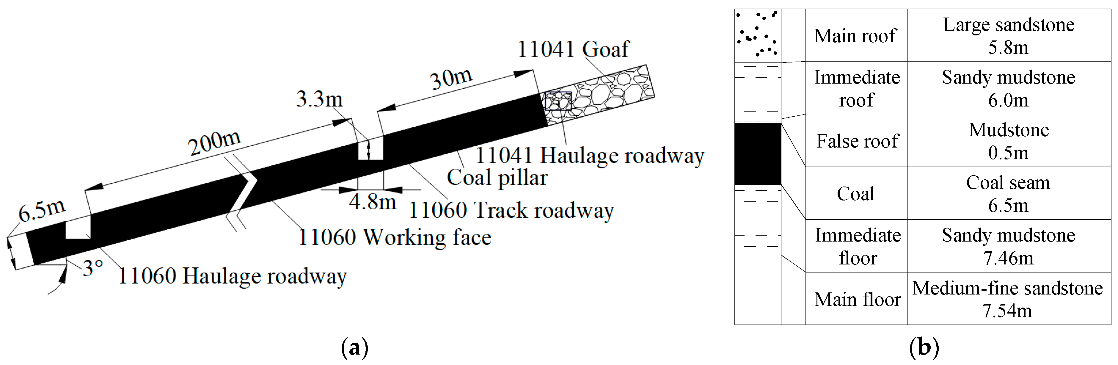
2.1. Engineering Geology

The ZhaoGu II mine is located in the eastern part of the Jiaozuo coalfield and is administratively under the jurisdiction of Huixian City in Xinxiang City, Henan Province, with a production capacity of 1.8 million tons and a total production capacity of 55.5 years. The buried depth of the 11041 working face of Zhaogu II Mine is 650–700 m, and the coal-seam dip angle and thickness are 3° and 6.5 m, respectively. The 11060 working face is located on the west side of the same level of the 11041 working face, and the mining plane and bar chart of 11041 are shown in Figure 1.
The 11060 track roadway was excavated along the top, and the section shape is rectangular. The size is width × height = 4.8 m × 3.3 m. The combined support of an anchor cable + steel ladder + 16# channel steel beam is adopted. The roof and side are supported by a φ20 × 2400 mm bolt specification, and the row spacing is 800 × 900 mm and 900 × 900 mm, respectively. The δ10 × 150 × 150 mm tray and steel ladder are used together. The length of the steel ladder is 4160 mm, and the row spacing is 900 mm. The roof anchor-cable specification is φ21.6 × 10,250 mm, and the row spacing is 1800 × 900 mm. The 16# channel steel beam with a length of 2500 mm is used in conjunction with the δ12 × 120 × 120 mm and δ12 × 80 × 80 mm steel plates. The mining engineering plan and top and bottom histogram of the 11041 working face is shown in Figure 1.

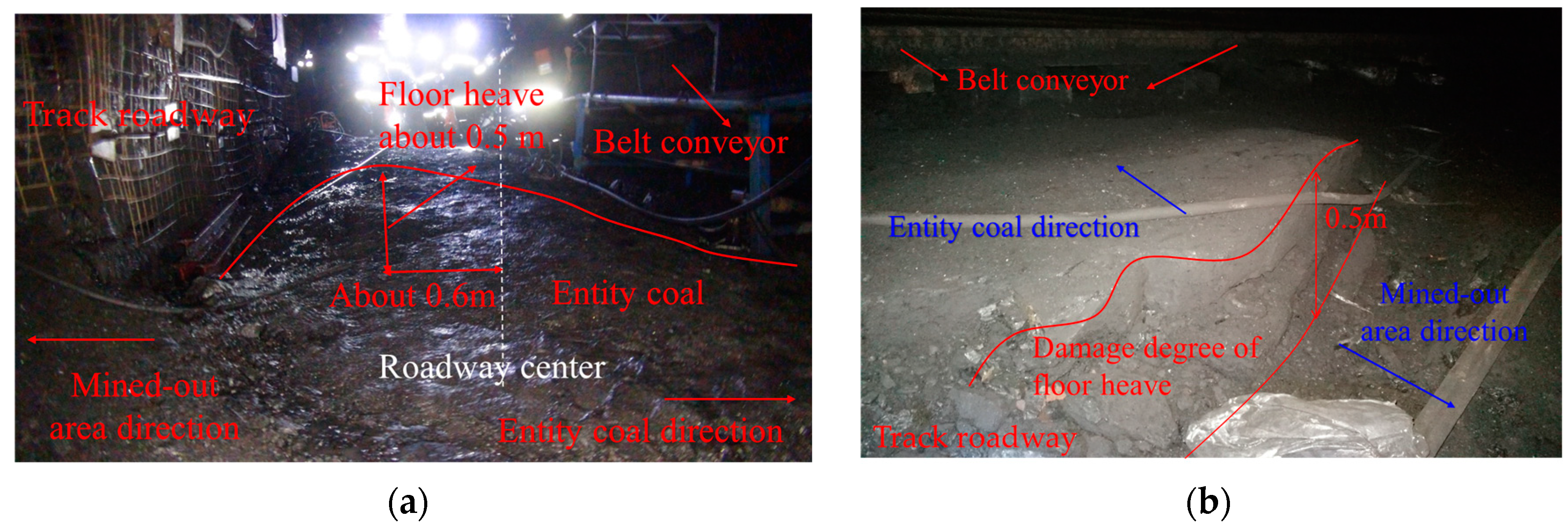
2.2. Characteristics of Asymmetric Floor Heave

During the mining of the 11041 face, the deformation of the surrounding rock in the 11060 track roadway was serious, and the large deformation floor heave and frequent undercover renovation seriously affected mining in the working face. The failure characteristics of the 11060 track roadway floor were collected and analyzed using an explosion-proof camera and geological radar. Currently, the working face is located in the 380 m position of the island lane and is experiencing periodic pressure. From Figure 2, it can be seen that the height of the floor heave of the roadway is 0.5 m, the maximum floor-heave position of the roadway is about 0.6 m from the center of the roadway, the overall floor-heave degree on one side of the goaf is greater than that of the solid coal side, and the floor heave of the roadway along the goaf in deep mining is seriously damaged and asymmetric.
A geological radar was used for detection along the excavation direction. In order to ensure the reliability of the results, the radar antenna should be in close contact with the surface of the floor as much as possible during the detection and move slowly and smoothly at a uniform speed to detect the damage and deformation of the roadway floor in the stable stage of excavation and mining. Figure 3 is the layout plan of the measuring points.
After noise reduction, one-dimensional and two-dimensional filtering, and other [22,23] processing, the geological radar-scanning characteristics of roadway floor failure at different stages were obtained, as shown in Figure 4. The roadway belongs to the stable area of excavation influence in the range of 200–300 m. It can be seen from Figure 4a that the color is basically the same in the range of 0.9 m in the vertical direction, and the color jump occurs at 0.9 m. There are many discontinuous color areas in the area, indicating that the rock strata in this range are separated and flipped and the large-scale development of cracks is the fracture area. In the vertical range of 0.9 m–3.5 m, the color changes greatly, the shock signal is obvious, and there are obvious strong reflections, scattering, or diffraction phenomena, indicating that this range is damaged and developed in a large number, which is a plastic zone; in the vertical range of 3.5 m–12.8 m, there is a yellow area of star spots, indicating that there is a small amount of fracture development. Therefore, the range of the fracture zone of the surrounding roadway-floor rock in the stable area affected by tunneling is 0.9 m, the range of the plastic zone is 0.9–3.5 m, and the maximum fracture-development depth of the floor is 12.8 m. The working face is located at 380 m of the roadway, and periodic weighting occurred at this time. According to Figure 4d, it can be seen that the floor fracture zone, plastic zone, and maximum fracture-development in the range of 300–380 m are 1.5 m, 1.5~6.5 m, and 21.8 m, respectively, under the influence of advanced mining. The roadway in the range of 300–330 m is far away from the working face and is less affected by advanced mining, but it is still affected to a certain extent. The depths of the fracture zone, plastic zone, and maximum fracture development of the floor are 1.2 m, 1.2~5.8 m, and 16.5 m, respectively, and the range of advanced influence of the working face is about 50 m. It can be seen from Figure 4e that 400–500 m is the roadway in the goaf area. The fracture zone, plastic zone, and maximum fracture-development depth range of the roadway floor are 1.3 m, 1.3~5.5 m, and 21.5 m, respectively, which are smaller than those of the roadway under pressure. This is because the gangue filling in the goaf recompacts the floor, and some areas of the floor are compacted and closed. The fracture zone and plastic zone are reduced to a certain extent, but the fracture development depth is basically unchanged. From the comparison of Figure 4a,d,e, it can be seen that the fracture zone, plastic zone, and maximum fracture-development depth of the roadway floor in the mining-affected area > roadway in the goaf > roadway in the stable area affected by tunneling.
According to Figure 4b,c, in the roadway section, the depth of the fracture zone, the plastic zone, and the maximum fracture-development depth of the roadway floor in the stable area affected by the excavation are 0.9 m, 0.9~3.5 m, and 12.8 m, respectively, and the center of the roadway is taken as the axis. The failure range of the floor near the coal-pillar side and the roadway floor on the solid-coal side is basically symmetrically distributed. When the working face is under pressure, the roadway in the mining-affected area is affected by mining. The fracture zone, plastic zone, and maximum fracture-development depth of the roadway floor near the solid-coal side are 1.2 m, 1.2~5.8 m, and 16.5 m, respectively, which are 33.3%, 65.7%, and 28.9% higher, respectively, than those in the excavation stage. The fracture zone, plastic zone, and maximum fracture-development depth of the roadway floor near the goaf side are 1.5 m, 1.5~6.5 m, and 21.8 m, respectively, which are 66.7%, 85.7%, and 70.3% higher, respectively, than those in the excavation stage. The depths of the fracture zone, plastic zone, and maximum fracture development of the roadway floor near the goaf side are greater than that of the solid-coal side, specifically, 25.0%, 12.1%, and 32.1% higher than that of the solid coal side, respectively. The maximum floor-heave failure position is located in the range of−0.6~−1.2 m from the center of the roadway, and the roadway presents asymmetric floor-heave failure characteristics.
Therefore, the floor-heave damage of the gob-side entry affected by deep mining is serious, and the degree of damage is roadway in the mining-affected area > roadway in the goaf > roadway in the stable area affected by excavation. The degree of floor heave and the damage range of floor fissures on the side of the goaf in the mining-affected area are significantly larger than those on the side of the solid coal. The maximum fissure-development point is biased towards the side of the goaf, and the floor heave of the deep-mining roadway is asymmetric.

3. Theoretical Analysis and Results

3.1. Effect of Deep Mining and Roadway Layout on Floor Failure

The mining depth of the mine is more than 700 m, which can be categorized as a deep mine, with a complex environment of three high-strength disturbances [24,25,26]. According to the slip-line theory, the failure area of the floor rock mass under the action of abutment pressure is simplified as a curved surface [27,28], and the asymmetric-failure-characteristics model of the floor with different roadway layouts under deep-mining abutment pressure was established, as shown in Figure 5. The failure radius R of the plastic zone of the roadway was defined, and the distance between the goaf on the right side of the roadway is L, the increased range of the abutment pressure is 2X0, and the length of the yield zone of the coal pillar is X0. The black curve ac, arc adb, and straight line oa and ab regions represent the floor-failure zone, the floor pre-peak-damage zone, the yield-failure zone of the coal pillar, and the stress-increase part of the elastic zone of the coal pillar under the action of the abutment pressure during shallow mining, respectively. The pink curve ac’, arc adb’, and straight line oa’ and ab’ regions represent the new floor-failure zone, the pre-peak-damage zone of the floor, the yield-failure zone of the coal pillar, and the elastic zone of the coal pillar formed by the abutment pressure under deep high stress, respectively.
In deep mining, the coal-pillar yield strength X0 and the failure radius R of the plastic zone of the roadway are as follows [28,29]:
X 0 ´ = m 2 n tan φ I n K d γ h + C cot φ n C cot φ
R = r 1 [ ( γ h + C c o t φ ) ( 1 s i n φ ) C c o t φ ] 1 s i n φ 2 s i n φ
where m is the coal-seam mining height, φ is the internal-friction angle of coal, C is the cohesion of coal, n is (1 + sin φ)/(1 − sin φ), and r1 is the radius of the roadway.
As shown in Figure 5, blue circles 1–3 represent different roadway-layout positions. ① When L + R > ob’ (roadway is located outside ob’), the plastic-failure zone of the roadway and the range of the floor-failure zone and damage zone under deep high-support pressure will not always overlap. At this time, the roadway is less or not affected by coal-seam mining, and asymmetric floor heave will not occur in the roadway. ② When oa< L + R < ob’ (the roadway is located in ab’), the roadway and the floor are in the stress-increasing part of the elastic zone and the pre-peak-damage zone. At this time, although the stress of the surrounding rock of the roadway is large and the stress of the surrounding rock on both sides of the roadway is different, it does not penetrate the plastic-failure zone of the floor under the deep high-abutment pressure. The roadway does not necessarily show asymmetric floor heave, and the roadway is in the elastoplastic stage. It is necessary to further determine whether the superimposed stress affected by tunneling will produce plastic deformation to determine whether asymmetric floor heave occurs. ③ When L + R < oa’ (the roadway is located within oa’), the roadway and the floor are in the yield-failure zone and the floor-failure zone. The roadway is in the plastic-yield zone and overlaps with the plastic zone of the roadway. The stress of the surrounding rock on both sides of the roadway is different. The asymmetric failure of the roadway occurs and the roadway is in the plastic yield stage. The law of asymmetry in the shallow part is consistent with the above-mentioned deep description. The superscripts need to be removed at each condition point to become oa, ob, and ab. ④ When oa < L + R < oa’ (the roadway is located within aa’), asymmetric failure does not necessarily occur when the roadway is in the shallow part, but it must occur in the deep part. ⑤ When oa< L + R < ob (the roadway is located within ab), the asymmetric failure of the roadway may be greatly increased due to the increase in stress. ⑥ When ob < L + R < ob’ (the roadway is located within bb’), asymmetric failure will not occur when the roadway is in the shallow part but may occur in the deep part.
Therefore, in deep mining, the range and peak value of abutment pressure become larger, which is transmitted to the floor and leads to the expansion of the floor stress and failure range. The increase in mining depth will increase the damage range of the coal pillars and floor under the goaf, which is more likely to produce asymmetric floor heave and more likely to induce roadway instability, floor-water inrush, and other disasters.

3.2. Stage Division and Characteristics of Deep-Mining Roadway along the Goaf

The following is a detailed analysis of the stress environment and floor-heave failure characteristics of the roadway when roadway position 3 is bound to have asymmetric failure. The near-field area of the roof at the lateral end of the working face closest to the coal pillar was taken as the research scope. According to the distribution law of stope-abatement pressure [28,30,31,32,33], the mining-affected roadway can be divided into stability zone I, advance mining-influence zone II, and post-mining residual-influence zone III, based on the distance from the working face, among which dynamic-load-impact zone IV will be produced when the working face is pressed. Moreover, the supporting-pressure peak value, distribution range, and distance from the end coal wall in dynamic-load-impact zone IV > advanced-mining-impact zone II > post-mining residual-impact zone III > tunneling-impact-stability zone I, as shown in Figure 6.

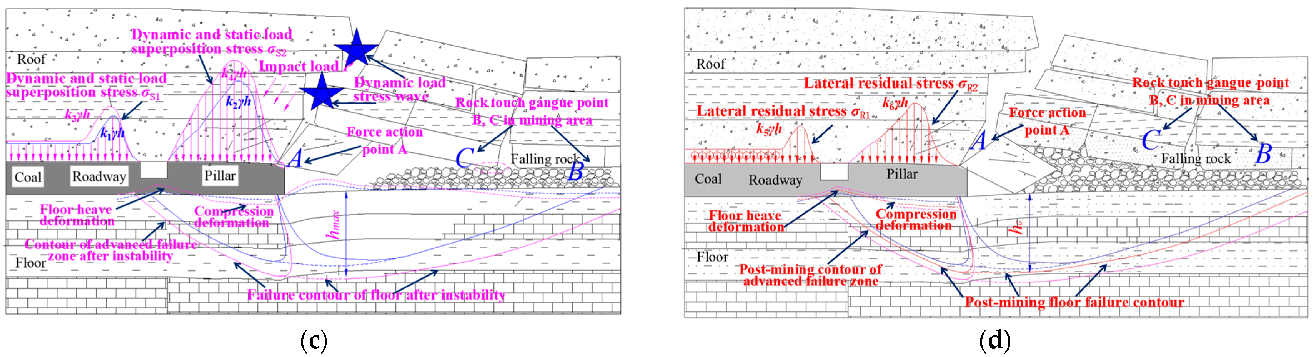
3.3. Stress Environment and Floor Asymmetric-Failure Characteristics at Different Stages of the Deep-Mining Roadway along the Goaf

Floor failure in coal mining will form a plastic-yield zone, unloading-failure zone, unloading-expansion zone, gangue-damage zone, and pre-peak-damage zone [24]. Combined with the near-field rock-strata control theory [34,35,36], it can be determined that the masonry-beam structure can easily be formed at the end of a working face after basic roof failure. Therefore, the floor-failure characteristics of the inclined goaf roadway in deep mining at all stages are shown in Figure 7.
When the roadway area is far from the face, the roadway is in the stable zone of tunneling-influence Ⅰ. Under the influence of tunneling, tunneling-disturbance force σE = K0γh is generated on both sides of the roadway, k0 is the concentration coefficient of tunneling-disturbance stress, γ is the rock-bulk density, h is the mining depth, and the stress on both sides of the roadway is equal without asymmetric floor heave, as shown in Figure 7a. When the roadway area is close to the working face, the roadway is in the advanced-mining-influence zone Ⅱ, which is affected by the lateral advanced-mining-abutment pressure of the adjacent working face. The surrounding rock stress of the coal-body side and the coal-pillar side of the roadway is the superposition of the advanced-mining-abutment pressure and σE, forming the advanced-static-load stress σA1 = k1γh and σA2 = k2γh, and k2 > k1 > k0. The stress difference on both sides of the roadway produces asymmetric floor heave. At this point, before the masonry-beam structure at the end of the working face becomes unstable, the lateral advanced-static-load stress σA2 generated above the coal pillar acts on the floor strata through the front arch foot A, the coal pillar, and the back arch foot B. The goaf and roadway floor are prone to upward-heave deformation due to the existence of a free surface, and the coal pillar and the gangue floor under the goaf produce compression deformation. The failure contour of the floor before the instability of the masonry beam is composed of the contour of the advance—failure zone, the contour of the failure-expansion zone, and the contour of the unloading-failure zone, as shown in Figure 7b. When the working face is under periodic pressure, the masonry-beam structure becomes unstable and the overlying strata in the inclined direction of the working face suffer rotary-instability and sliding-instability damage. A dynamic-load-source stress wave is generated, which is transmitted to the roadway and surrounding coal-pillar rock in the form of force or energy to form dynamic load–impact load P. In addition, the dynamic- and static-load superimposed stress σS1 = k3γh and σS2 = k4γh, and k4 > k2 > k3 > k1 > k0, are formed on the coal-body side and the coal-pillar side by the tunneling-disturbance stress and the lateral advanced-static-load stress. The superimposed stress of dynamic and static load on the coal pillar and goaf floor increases the failure range of the floor and the asymmetric floor-heave degree, forming a new failure profile of the floor after the instability, in which the maximum failure depth of the floor and the length of the floor-heave area on the coal-pillar side increase significantly, and the floor-heave deformation of the goaf and roadway floor and the compressive-deformation degree of the floor under the coal pillar and goaf gangue increase significantly compared to before the instability, as shown in Figure 7c. When the roadway area lags behind the working face for a certain distance, the roadway is in post-mining residual-influence zone Ⅲ, and the lateral abutment pressure no longer changes significantly. In this case, the lateral abutment pressure is superimposed with σE on the coal side and pillar side of the roadway to form the advanced-static-load stress σR1 = k5γh and R2 = k6γh, because the advanced abutment pressure is greater than the lateral residual abutment pressure. Therefore, k4 > k2 > k6 > k0, k3 > k1 > k5 > k0; at that time, the floor forms a new post-mining floor-failure profile. Since the floor has been damaged and the caving gangue will compact the floor after it is stabilized, the new post-mining floor-failure profile lies between the pre-instability and post-instability failure profiles, as shown in Figure 7d.
To sum up, when the adjacent working face is under periodic pressure in deep mining, the lateral floor failure has a strong influence, and the dynamic-load disturbance will increase the floor-failure range and cause a difference in the surrounding rock stress between the coal-pillar side and the solid-coal side of the goaf roadway during primary mining, resulting in asymmetric floor heave when the critical load of the floor failure is exceeded and the floor heave on the goaf side is larger than that on the solid-coal side. According to the slip-line theory, due to the difference in stress size, it can be determined that the post-mining residual-influence area of the masonry beam after its instability in Figure 7c and the failure depth of the floor in Figure 7d are greater than those before the instability of the masonry beam in Figure 7b, and the position of the maximum floor heave is more and more shifted towards the center of the roadway.

3.4. Stress Distribution and Maximum Failure Depth of a Point under Dynamic-Load Disturbance

According to the Saint-Venant principle, the increasing part of the abutment pressure on the side of the coal pillar is equivalent to a uniform load. The load concentration is (k + 1)γh/2 and the action width is 2X0. According to the semi-infinite-body theory, the maximum and minimum principal stress of any point M of the floor under its influence is [29,37]:
σ 1 a , σ 3 a = k + 1 2 π γ h [ α ± sin α ]
where k is the maximum stress-concentration factor, γ is the average bulk density of overlying strata, h is the buried depth, and α is the angle difference between β1 and β2.
The impact load p of the roof-structure instability on the coal-pillar end is [38]:
P = { 1 + 1 + 2 [ m Σ h ( K P 1 ) ] E d Σ h γ B h B L B } γ B h B L B e η x L d
where m is the thickness of coal seam, kp is the rock-bulking coefficient, and Ld and ∑h are the direct roof-hanging distance and the direct roof-caving thickness, respectively. γB, hB, and LB are the volume force, thickness, and length of the masonry-beam structure, respectively. x is the distance between the power source and the coal seam; η = 2 − v/(1 − v), v is the Poisson’s ratio.
The impact load p acts on the coal pillar and is superimposed with the abutment pressure and simplified as a uniformly distributed load σp, and the action width grows to 2X0′. Considering the self-weight stress of the rock mass in the floor and simplifying the study to a plane-strain state, the maximum and minimum principal stresses of any point M (vertical distance z from the floor) of the floor under strong disturbance during deep weighting are:
σ 1 d , σ 3 d = ( k + 1 2 π γ h + p π ) ( α ± sin α ) + γ z
Because the working face is buried at a depth of 700 m and the Mohr–Coulomb criterion is not applicable to high confining-pressure conditions, the Griffith-failure criterion is used ( σ 1 + 3 σ 3 > 0 ) [28,29]:
( σ 1 σ 3 ) 2 = 8 ( σ 1 + σ 3 ) R t
where Rt is the uniaxial tensile strength of the floor-rock mass.
Put Equation (5) into Equation (6) to obtain the extreme value by taking the derivative, and then put it into Equation (6) to solve the maximum crack depth hmax of the floor:
h max = σ p 8 π 2 γ R t ( σ p σ p 2 16 π 2 R t 2 4 π R t sin 1 4 π R t σ p )
Substituting σp = (k + 1)γh/2 + p gives:
h max = { ( k + 1 ) γ h 16 π 2 γ R t + { 1 + 1 + 2 [ m Σ h ( K P 1 ) ] E d Σ h γ B h B L B } γ B h B L B e η x 8 π 2 γ R t L d } × ( ( k + 1 ) γ h 2 + { 1 + 1 + 2 [ m Σ h ( K P 1 ) ] E d Σ h γ B h B L B } γ B h B L B e η x L d { ( k + 1 ) γ h 2 + { 1 + 1 + 2 [ m Σ h ( K P 1 ) ] E d Σ h γ B h B L B } γ B h B L B e η x L d } 2 16 π 2 R t 2 4 π R t sin 1 ( 4 π R t ( k + 1 ) γ h 2 + [ 1 + 1 + 2 [ m Σ h ( K P 1 ) ] E d Σ h γ B h B L B ] γ B h B L B e η x L d ) )
From Equations (7) and (8), it can be seen that the maximum fracture-damage depth of the bottom slab is positively correlated with the burial depth and coal thickness, i.e., the maximum fracture-damage depth of the bottom slab increases with the increase in mining depth and increases with the increase in mining thickness.

4. Numerical Simulation and Results

The 3DEC discrete-element numerical-simulation software was used to analyze the floor-heave-failure characteristics of roadways in different mining stages, analyze the evolution law, and study the influence of dynamic-load impact on floor failure.

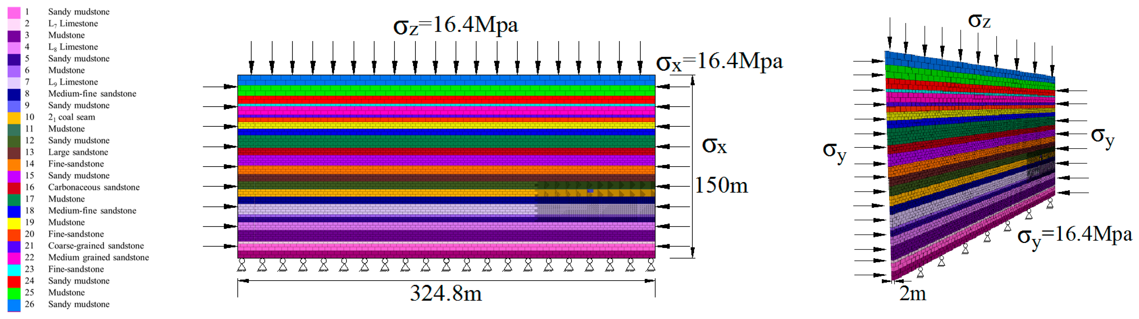
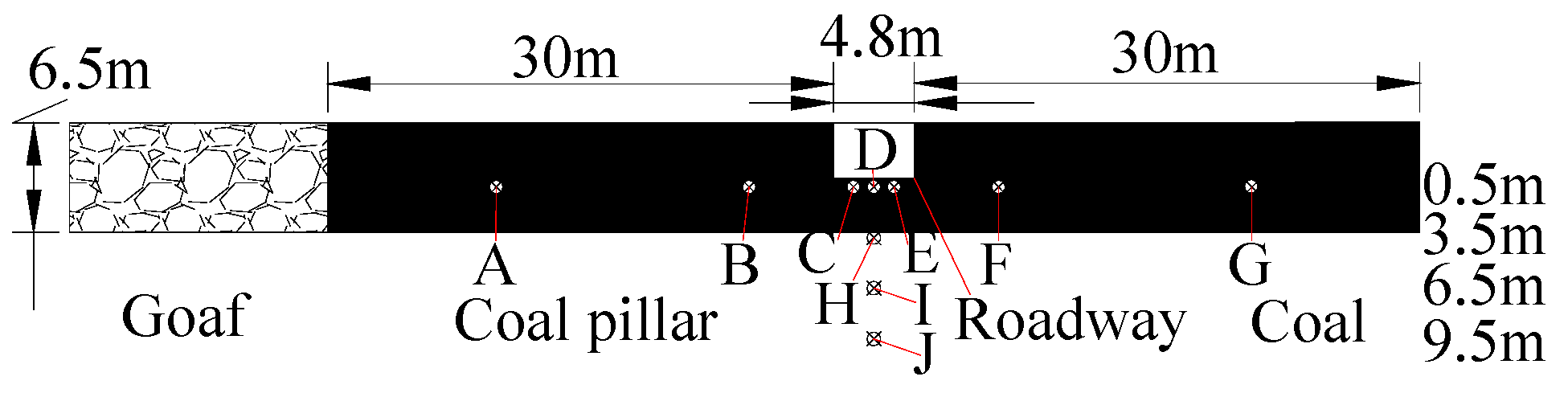
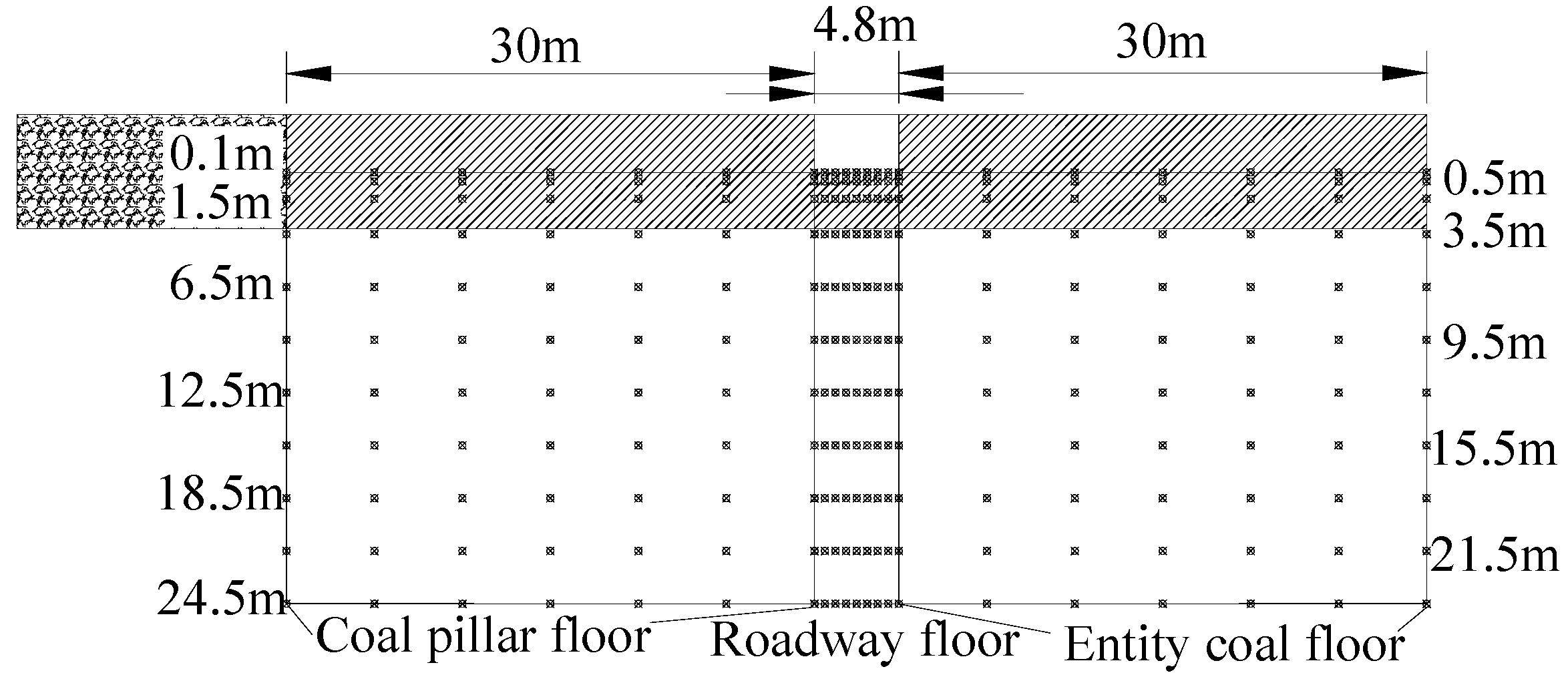
4.1. Simulation-Model Building

According to the geological conditions of the roof and floor of the mine, the coal strata are simplified into 26 layers, and therefore the model size was length × width × height = 334.8 m × 2 m × 150 m. An equivalent overburden load of 16.4 MPa was applied to the upper part, and a horizontal stress of 16.4 Mpa was applied to the front, back, left, and right boundaries. The horizontal displacement was fixed in the front, back, left, and right, and the lower boundary was fixed in the horizontal and vertical directions. The Mohr–Coulomb model (cons = 1) was used for the constitutive model of the block, and the Coulomb slip model (jcons = 2) was used for the joint fissure. The mechanical parameters of blocks and joints were taken from rock-mechanics experiments and weakened by the Hoek–Brown criterion. The 3DEC numerical-simulation model and boundary conditions are shown in Figure 8. The numerical-simulation mechanical parameters of the coal-rock mass at different depths are shown in Table 1.
According to the site research, the length of the 11060 working face and adjacent 11041 working face of ZhaoGu Second Mine are 200 m and the width of the coal column between the two working faces is 30 m. Due to the limitation of the article length and the memory of 3DEC transportation, the model was built in thin slices. Because of the analysis of the top breaking characteristics in the direction of the vertical working-face advancement, the model was excavated 200 m at a time for the working face in order to simplify the model, and the coal pillar between the roadway and the working face was left at 30 m.

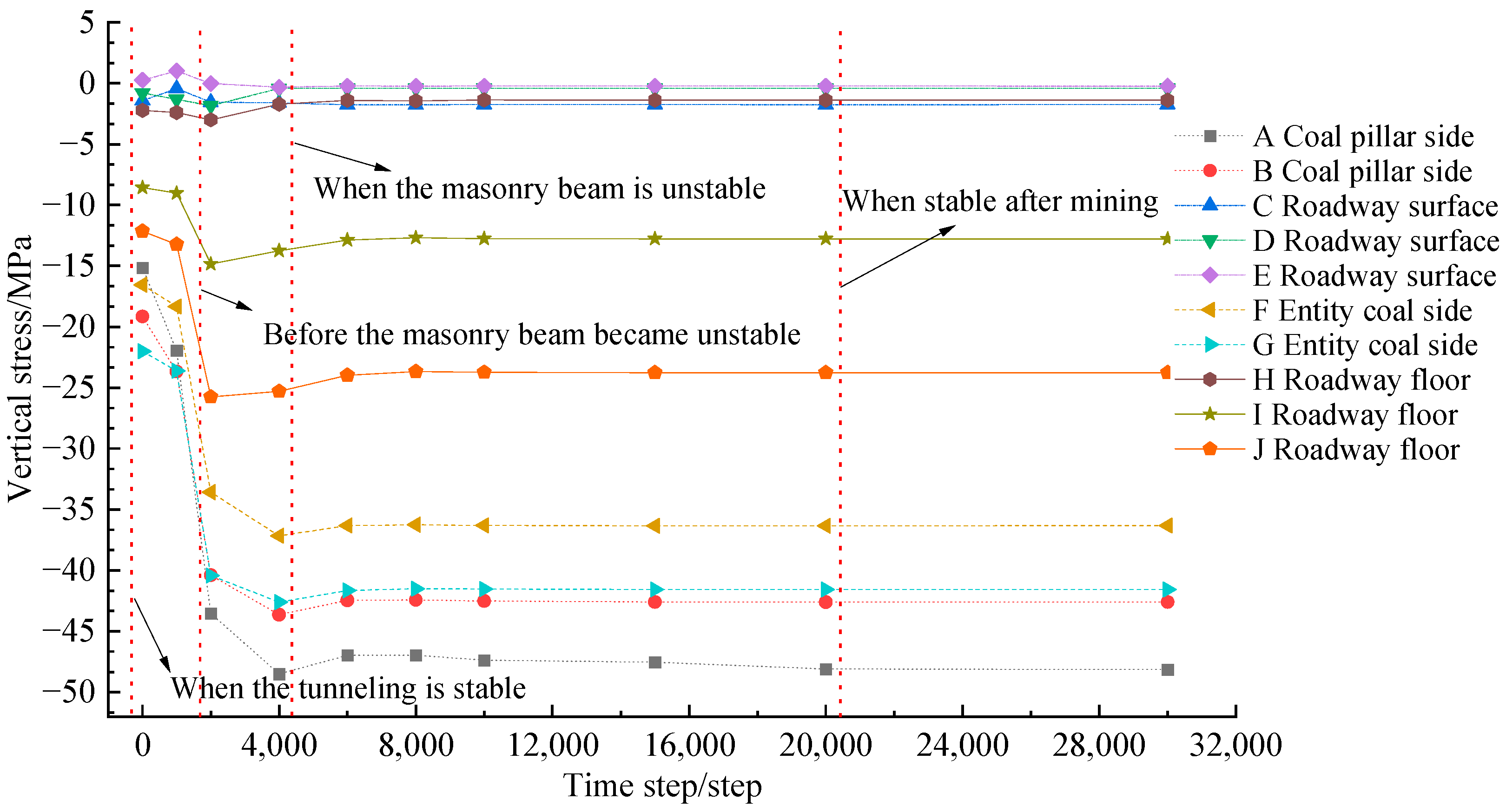
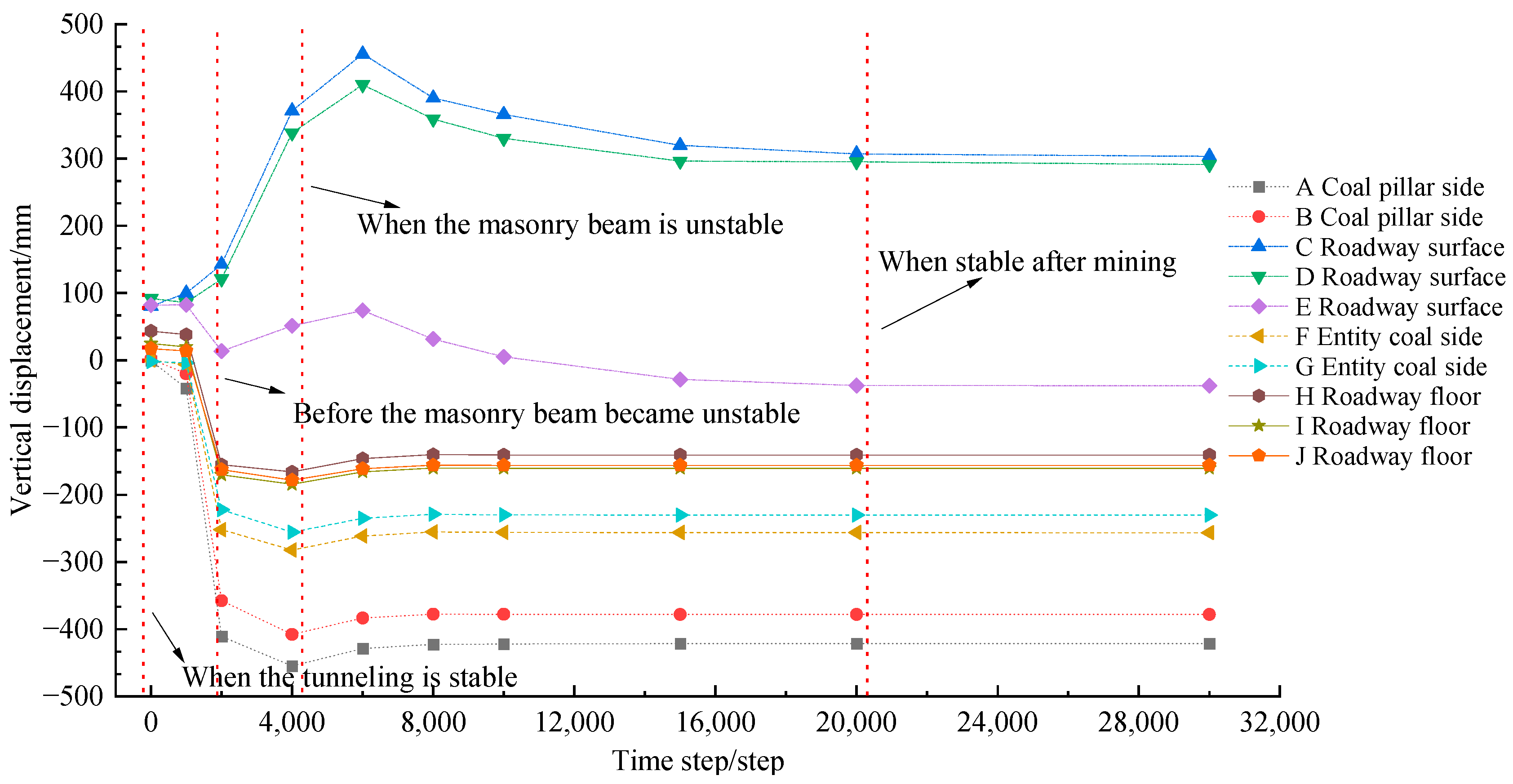
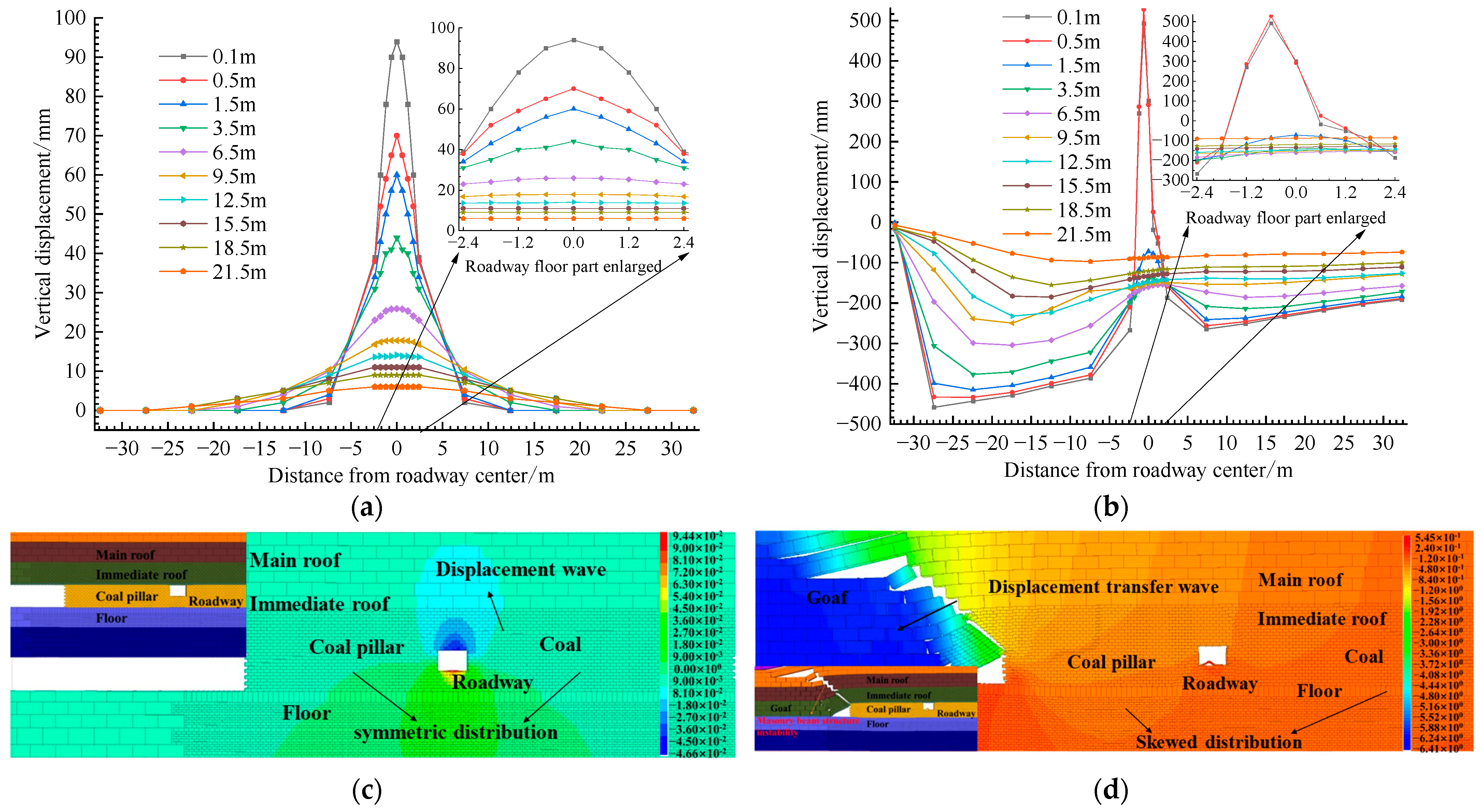
4.2. Analysis of Results under Different Mining Stages

The different stages of the roadway were represented by different operation time steps, and the different breakage characteristics of the lateral direction of the working face after the statistical excavation are shown in Figure 9. Before excavation, the roadway belonged to the excavation influence-stabilization stage, and after excavation, with the increase in the computing time step, the masonry beam and masonry-beam structural instability were formed at the end of the coal-column side of the working face. Before the calculation, the roadway belonged to the end of the impact-stabilization stage of the excavation and the mining stress had not started to transfer; at 2000 computing time steps, the roadway was in the pre-destabilization stage of the masonry beam; at 4000 computing time steps, the roadway was in the destabilization dynamic-load-impact stage of the masonry beam; and at 20,000 computing time steps, the roadway was in the post-mining residual-impact stage and the roadway structure basically did not change.
In order to deeply study the vertical-stress and vertical-displacement evolution characteristics of the floor at different stages of the roadway, the center point of the roadway floor was used as the origin for the −2.4~2.4 m roadway floor, −32.4~−2.4 m for the floor below the coal column, and 2.4~32.4 m for the solid coal-side floor; the X-axis was the distance from the center of the roadway floor and the Y-axis was the depth from the center of the roadway floor. Layout A–J included a total of 10 measurement points, including A (−17.4, −0.5), B (−7.4, −0.5), C (−1.2, −0.5), D (0, −0.5), E (1.2, −0.5), F (7.4, −0.5), G (17.4, −0.5), H (0, −3.5), I (0, −6.5), and J (0, −9.5). The arrangement of measurement points at different time steps is shown in Figure 10, and the vertical-stress and vertical-displacement distribution curves under different time steps of the bottom rock layer were drawn as shown in Figure 11 and Figure 12.
As can be seen from Figure 11, (1) with the increase in calculation time, the vertical stress, tensile stress, and compressive stress of the coal pillar, roadway, and solid-coal floor all showed a trend of first increasing, then decreasing, and finally gradually stabilizing. Without calculation, the roadway belonged to the stable stage of excavation influence. When the calculation steps were 2000 steps after excavation, the vertical stress of the coal pillar, roadway, and solid-coal floor generally increased, which is because the masonry-beam structure was generated on the working face and the roadway was in the stage before the masonry beam became unstable. When the calculation steps were 4000 steps after excavation, the instability of the masonry beam formed the dynamic-load impact and the vertical stress rapidly increased to the peak. Then, with the increase in the time step, the energy of the floor was released and the floor was compacted after the caving gangue in the goaf was stabilized. The coal pillar and tunnel floor gradually became stable. (2) The vertical stress of point lines A and B affected by mining was always greater than that of lines F and G, indicating that the influence of the coal-pillar side of the floor was greater than that of the solid-coal side when mining the adjacent working face. (3) As the distance between A and G, B and F, and C and E was closer to the goaf, the growth rate of the vertical stress was faster, the time to grow to the peak point was shorter, the peak point was larger, the influence of mining was more and more serious, and the distribution of vertical stress presented obvious asymmetry. (4) The vertical stress of the dotted lines C, D, and E and the solid line H hovered within −5~+ 5 Mpa; the stress of solid line I was lower than that of the original rock; and the stress of solid line J was basically equal to 23.7 Mpa, indicating that the floor heave of 0–3.5 m was very serious and the stress was basically released. Plastic failure still occurred at 6.5 m of the floor and the stress was partially released. The failure of the roadway floor was basically non-plastic at 9.5 m.
It can be seen from Figure 12 that the evolution characteristics of vertical displacement of the floor under different stages of the deep-mining roadway were basically consistent with vertical stress. With the increase in time, the vertical displacement of each base point of deep floor increased first, then decreased and gradually stabilized. At the symmetrical point of the roadway center, the vertical-displacement growth rate and displacement value of each measuring point in the inner floor of the coal pillar and the side floor of the roadway coal pillar were much larger than those in the inner floor of the solid coal and the solid-coal floor of the roadway, and the vertical-displacement distribution showed obvious asymmetry. This is because with the time-step operation, the mining influence was gradually transmitted in the order of coal pillar–surrounding roadway rock–solid coal. The farther the distance, the smaller the influence. The deeper the distance, the smaller the influence. With the mining influence, the surrounding rock of the roadway was damaged by the load exceeding the strength, the roadway was deformed in a large area, the two sides were close, the roof fell, the floor heaved, and the displacement reached the maximum value. Then, the compaction displacement gradually decreased to a balanced value and the roadway presented asymmetric floor heave.

4.3. Characterization of the Asymmetric Bottom Drum of the Roadway

In order to analyze the characteristics of floor-heave failure caused by dynamic-load impact-disturbance damage in deep mining, the vertical-stress and vertical-displacement values at different depths (0.1 m, 0.5 m, 1.5 m, 3.5 m, 6.5 m, 9.5 m, 12.5 m, 15.5 m, 18.5 m, 21.5 m) of roadway-floor strata were monitored. The arrangement of measuring points is shown in Figure 13. The origin was the center point of the roadway floor at −2.4~2.4 m, −32.4~−2.4 m was the floor below the coal pillar, and 2.4~32.4 m was the floor of the solid-coal side.
The vertical-stress and vertical-displacement distribution curves of different depths of roadway floor under dynamic-load disturbance were drawn as shown in Figure 14 and Figure 15. It can be seen from Figure 14 that under the influence of dynamic-load-impact disturbance, the vertical stress of the roadway, coal pillar, and solid-coal floor changed from a uniform symmetrical distribution to an asymmetric distribution, and the vertical-stress value in the range of 0–21.5 m of the floor generally increased. The vertical-stress distribution of the floor below the coal pillar (−32.4~−2.4 m from the center of the roadway) and the floor of the solid-coal side (2.4~32.4 m from the center of the roadway) changed from a uniform parallel distribution to an inverted-V-shaped distribution, and the stress value generally increased. The stress of the floor increased first and then decreased with the distance from the center of the roadway. The peak point of the floor below the coal pillar was located at about −17.5 m from the center of the roadway, which was biased towards the side of the goaf, and the peak value was −71 Mpa, which was much larger than the original rock stress; the peak point of the floor below the solid coal was located about 12.5 m from the center of the roadway, which was biased to the side of the goaf, and the peak value was −64.7 Mpa. In the range of the roadway floor (−2.4~2.4 m from the center of roadway), the peak point was not in the center of displacement of the roadway due to the influence of dynamic load but in the side of the coal pillar. The peak point was located about −0.6 m from the center of the roadway, and the peak value increased from 2.0 Mpa to 5.9 Mpa, with an increase of 195%. The stress of the roadway floor was generally reduced from 3.5 m to 6.5 m, and the offset change was obvious in 6.5 m. Under dynamic-load disturbance, the surface of the roadway was seriously relieved and the tensile failure was obvious. The range of pressure failure increased obviously on the side of the goaf, showing asymmetric floor heave, and the range of plastic failure increased from 3.5 m to 6.5 m.
It can be seen from Figure 15 that the vertical-displacement distribution of the rock mass at the bottom of the roadway, coal pillar, and solid coal was basically consistent with the vertical stress under the influence of dynamic-load-impact disturbance. The peak point of the vertical displacement of the floor below the coal pillar was located at about −27.5 m from the center of the roadway, which was biased towards the side of the goaf, and the peak value was −458.6 mm; the peak point of the floor below the solid coal was located about 7.5 m from the center of the roadway, which was biased to the side of the goaf, and the peak value was −264.6 mm. The peak vertical displacement of the roadway floor increased from 94.0 mm to 527.3 mm, with an increase of 461%. The floor-heave damage was serious, and the floor heave near the coal-pillar side was much larger than the solid-coal side, showing an asymmetric floor heave.

5. Discussion and Applicability

5.1. Bottom-Drum Cause and Control Ideas
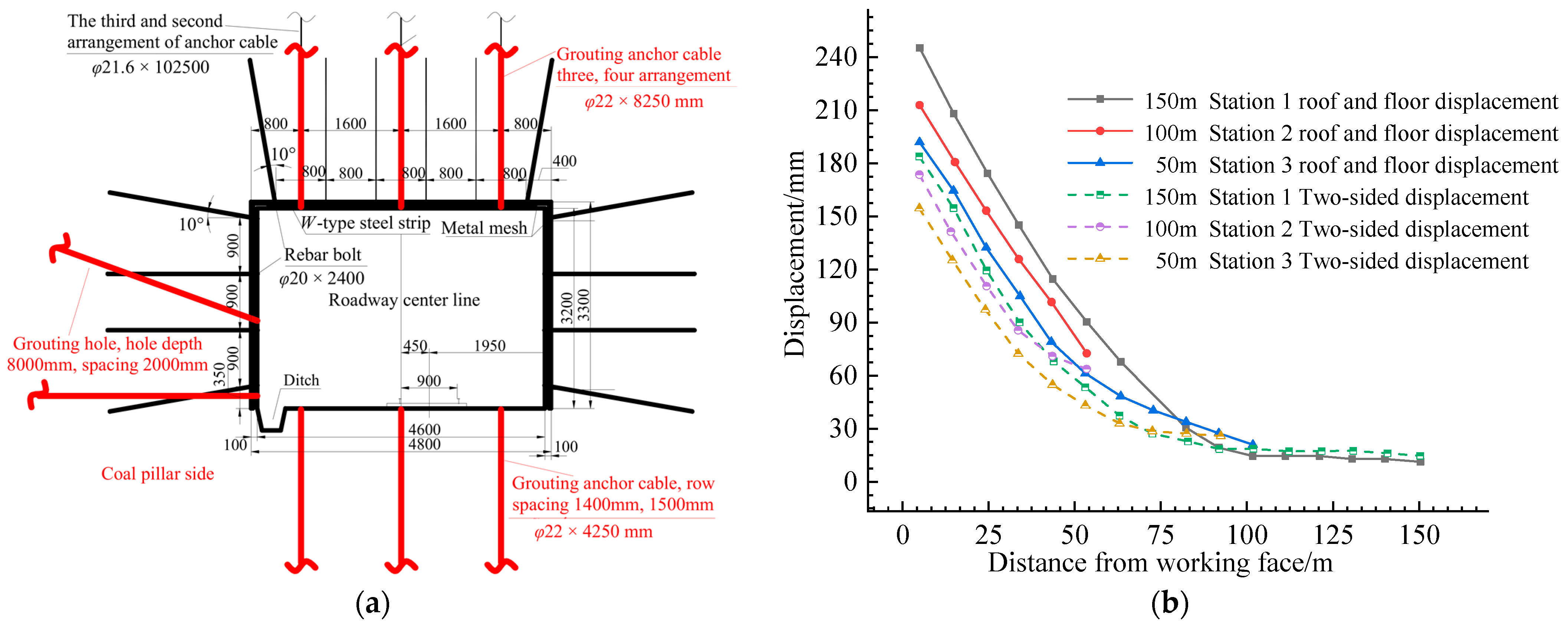
The 11060 track roadway has high roadway stress, strong dynamic-load-mining influence, a weak floor, confined water mining, and other maintenance difficulties. These factors all increase the difficulty of roadway maintenance to varying degrees, resulting in the asymmetry of the surrounding rock structure and stress distribution. Coupled with the repeated movement of the overburdened structure, the poor lithology of the floor, the mining of confined water, and the poor adaptability and low efficiency of the supporting structure finally induce asymmetric floor heave. The research results can provide an important reference for the control of roadway floors under similar geological conditions. The exact location and depth of the roadway floor can be measured in the field and simulated numerically.
Aiming at the asymmetric floor heave of a roadway, a control scheme of “one reinforcement, two pressure relief” is put forward. (1) Reinforcement: Optimize the support parameters, change the support measures of the roof and two sides, and carry out undercover and grouting reinforcement of the floor. (2) For surrounding rock-roof cutting-pressure relief of the roadway, reduce or release the high stress on the roadway and floor. For pressure relief, with a drilling diameter of φ75 mm and every 5 m, blasting or hydraulic fracturing is performed on both sides of the roadway to relieve pressure and unload the gravity of the overlying rock mass.

5.2. Field Test

Based on the reinforcement scheme of Zhao Gu I mine and improved by a field test [39,40], the mine site adopted the scheme of grouting-anchor-cable reinforcement. On the basis of the original support, the φ22 × 8250 mm grouting-anchor cable was used in the roadway roof, and three and four were staggered. The row spacing was 1400 × 1000 mm (3 roots/row) and 1350 × 1000 mm (4 roots/row), and the tray adopted a δ16 × 300 × 300 mm high-strength tray. The roadway was reinforced by grouting, and the hole depth and spacing were 8000 mm and 2000 mm, respectively. The floor was arranged with a φ22 × 4250 mm grouting-anchor cable, and the row spacing was 1400 × 1500 mm. The anchoring agent and tray were consistent with the roof-anchor cable. By arranging three observation stations in the advanced section of the roadway, with a spacing of 50 m, the cross-observation method was used to monitor the roof and floor convergence and the convergence of the t wo sides. The reinforcement scheme and effect of the grouting bolt are shown in Figure 16.
It can be seen from Figure 16 that after grouting-anchor-cable reinforcement, the maximum displacement of the roof and floor of the roadway was 245.1 mm and the maximum displacement of the two sides was 183.8 mm. The maximum displacement of the roof and floor of the roadway was generally greater than the maximum displacement of the two sides. There was little difference in the variation of the roof and floor and two-side displacement 6 m away from the working face, and the maximum displacement of the roof, floor, and two sides was basically unchanged 100 m away from the working face. This indicates that the maximum advanced-mining-influence distance is 100 m and the mining-influence range is small, at 60 m. Compared with the numerical-simulation results in Section 4, the surrounding-rock tunnel is effectively controlled and the grouting-anchor-cable support design is reasonable.
At present, roof-cutting and pressure-relief measures have not been adopted in the mine. Adjacent mines have adopted the “one beam three columns + bottom beam” restrictive reinforcement and roof-cutting and retaining-roadway scheme. The large flow and high-pressure hydraulic-fracturing system and the effect of the retaining roadway are shown in Figure 17. It can be seen that the roadway has a good effect. Therefore, it can be proven that the reinforcement of the surrounding rock and the pressure relief of roof cutting can effectively control the asymmetric floor heave of the roadway and provide technical reference for the mine.

6. Conclusions

The following main conclusions can be drawn:
(1)
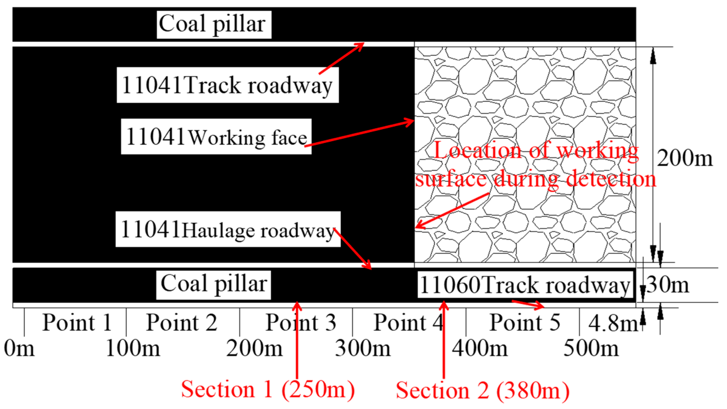
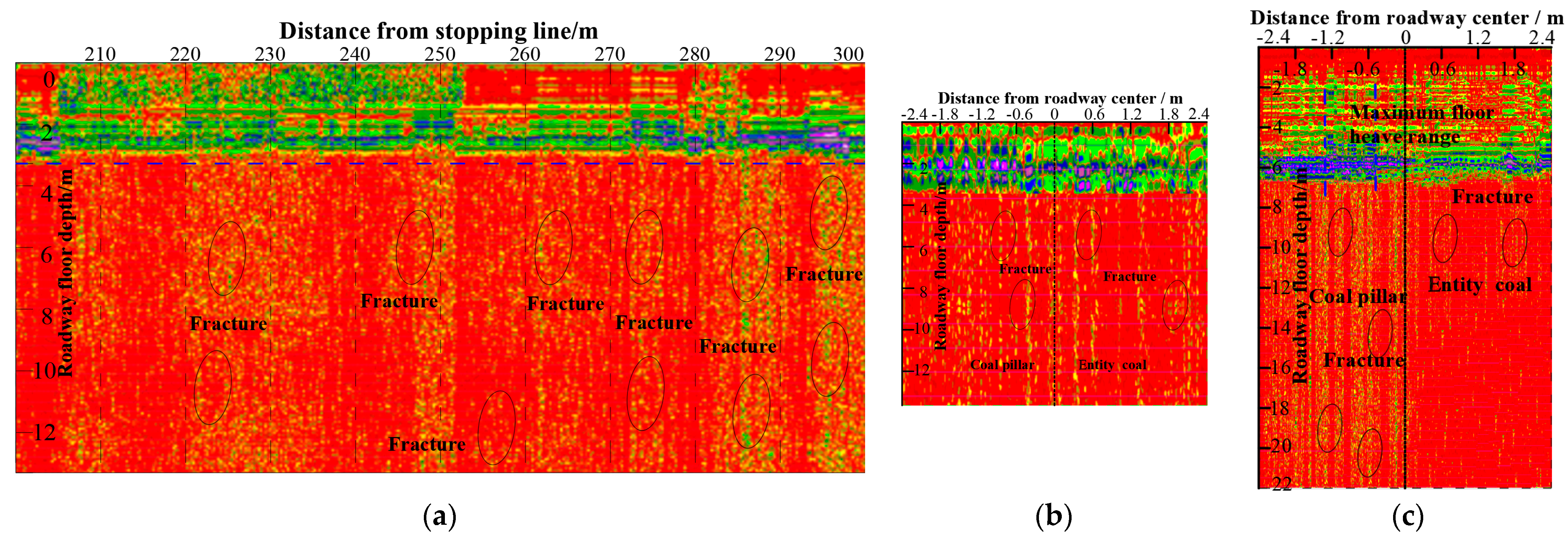
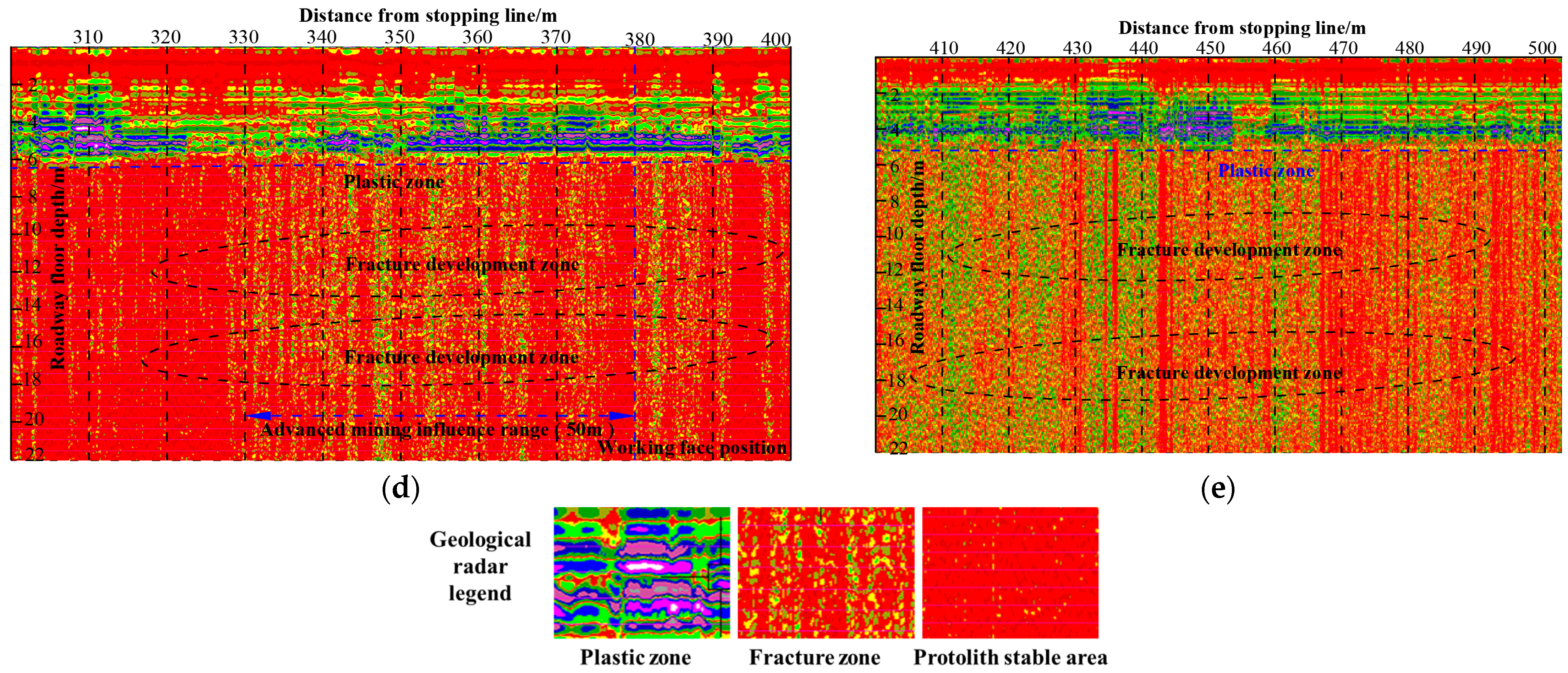
According to the geological-radar and field-observation analysis, the asymmetric large-deformation floor-heave-failure characteristics of the goaf roadway affected by deep mining were determined, and the floor-heave degree of roadway in the area affected by mining and the range of maximum fracture development > that of roadway in goaf > that of roadway in the area affected by mining stability were obtained.
(2)
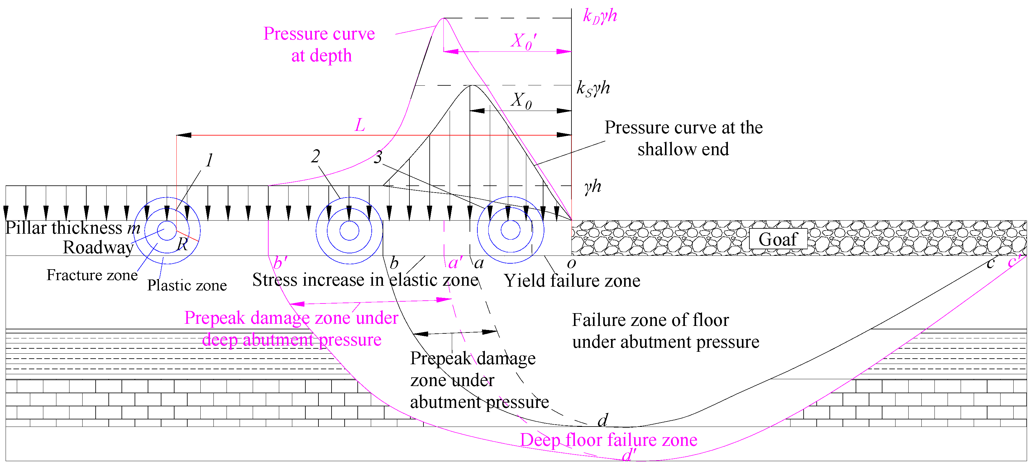
The floor asymmetric-failure-characteristics model of different roadway layouts under deep-mining abutment pressure was established, the influences of deep mining and roadway layout on mining roadways were analyzed and the conditions of roadway asymmetric failure were determined. Combined with the Griffith-failure criterion, the maximum crack-development depth of the floor was given and the influence of mining depth on it was analyzed.
(3)
The distribution characteristics of floor stress and displacement field at different stages of the roadway were simulated using 3DEC discrete-element numerical-simulation software and the asymmetric-floor-heave characteristics of roadway were analyzed under dynamic-load disturbance. Aiming at the asymmetric floor heave of roadway, the control scheme of “grouting-anchor-cable reinforcement and cutting-roof pressure relief” was proposed. The rationality of the control scheme was verified by in situ deformation observation of the roadway surrounding rock.

Author Contributions

Conceptualization, W.W. and G.Z.; methodology, W.W.; investigation, W.W. and C.L.; writing-original draft, W.W., C.L. and W.Z.; formal analysis, W.W., W.Z. and Y.S.; writing—review and editing, W.W. and G.Z. All authors have read and agreed to the published version of the manuscript.

Funding

This research was funded by the National Natural Science Foundation of China (51904303).

Institutional Review Board Statement

Not applicable.

Informed Consent Statement

Not applicable.

Data Availability Statement

The data used to support the findings of this study are available from the corresponding author upon request.

Conflicts of Interest

The authors declare no conflict of interest.

References

  1. Xie, H.P.; Gao, F.; Ju, Y. Research and development of rock mechanics in deep ground engineering. Chin. J. Rock Mech. Eng. 2015, 34, 2161–2178. (In Chinese) [Google Scholar]
  2. Zhai, X.; Huang, G.; Chen, C.; Li, R. Combined Supporting Technology with Bolt-Grouting and Floor Pressure-Relief for Deep Chamber: An Underground Coal Mine Case Study. Energies 2018, 11, 67. [Google Scholar] [CrossRef] [Green Version]
  3. Lai, X.; Xu, H.; Shan, P.; Kang, Y.; Wang, Z.; Wu, X. Research on Mechanism and Control of Floor Heave of Mining-Influenced Roadway in Top Coal Caving Working Face. Energies 2020, 13, 381. [Google Scholar] [CrossRef] [Green Version]
  4. Wu, H.; Jia, Q.; Wang, W.; Zhang, N.; Zhao, Y. Experimental Test on Nonuniform Deformation in the Tilted Strata of a Deep Coal Mine. Sustainability 2021, 13, 13280. [Google Scholar] [CrossRef]
  5. Zhang, D.; Bai, J.; Yan, S.; Wang, R.; Meng, N.; Wang, G. Investigation on the Failure Mechanism of Weak Floors in Deep and High-Stress Roadway and the Corresponding Control Technology. Minerals 2021, 11, 1408. [Google Scholar] [CrossRef]
  6. Zhang, Z.; Shimada, H. Numerical Study on the Effectiveness of Grouting Reinforcement on the Large Heaving Floor of the Deep Retained Goaf-Side Gateroad: A Case Study in China. Energies 2018, 11, 1001. [Google Scholar] [CrossRef] [Green Version]
  7. Zhu, L.; Liu, C.; Gu, W.; Yuan, C.; Wu, Y.; Liu, Z.; Song, T.; Sheng, F. Research on Floor Heave Mechanisms and Control Technology for Deep Dynamic Pressure Roadways. Processes 2023, 11, 467. [Google Scholar] [CrossRef]
  8. Qin, D.; Wang, X.; Zhang, D.; Chen, X. Study on Surrounding Rock-Bearing Structure and Associated Control Mechanism of Deep Soft Rock Roadway Under Dynamic Pressure. Sustainability 2019, 11, 1892. [Google Scholar] [CrossRef] [Green Version]
  9. Karampinos, E.; Hadjigeorgiou, J.; Hazzard, J.; Turcotte, P. Discrete element modelling of the buckling phenomenon in deep hard rock mines. Int. J. Rock Mech. Min. Sci. 2015, 80, 346–356. [Google Scholar] [CrossRef]
  10. Vakili, A.; Sandy, M.; Alercht, J. Interpretation of non-linear numerical models in geomechanics-a case study in the application of numerical modelling for raise bored shaft design in a highly stressed and foliated rock mass. In Proceedings of the 6th International Conference and Exhibition on Mass Mining, Sudbury, ON, Canada, 10–14 June 2012. [Google Scholar]
  11. He, M.C.; Wang, X.Y.; Liu, W.T.; Yang, S.B. Numerical simulation and asymmetric deformation of deep soft rock roadway in Kongzhuang Mine. Chin. J. Rock Mech. Eng. 2008, 4, 673–678. (In Chinese) [Google Scholar]
  12. Ma, N.J.; Zhao, X.D.; Zhao, Z.Q.; Li, J.; Guo, X.F. Stability analysis and control technology of mine roadway roof in deep mining. J. China Coal Soc. 2015, 40, 2287–2295. (In Chinese) [Google Scholar]
  13. Zhao, Z.Q.; Ma, N.J.; Guo, X.F.; Zhao, X.D.; Fan, L. Falling principle and support design of butterfly-failure roof in large deformation mining roadways. J. China Coal Soc. 2016, 41, 2932–2939. (In Chinese) [Google Scholar]
  14. Li, J.; Ma, N.J.; Ding, Z.W. Heterogeneous large deformation mechanism based on change of principal stress direction in deep gob side entry and control. J. Min. Saf. Eng. 2018, 35, 214–219. (In Chinese) [Google Scholar]
  15. He, F.L.; Gao, F.; Sun, Y.J.; Li, S.J.; Song, B.H.; Yang, Y.F. Multiple-cable-girder-truss asymmetric support mechanism and its application in the roadway of fully mechanized top coal caving face with narrow coal pillar. J. China Coal Soc. 2015, 40, 2296–2302. (In Chinese) [Google Scholar]
  16. Zhang, G.C.; He, F.L. Asymmetric failure and control measures of large cross-section entry roof with strong mining disturbance and fully-mechanized caving mining. Chin. J. Rock Mech. Eng. 2016, 35, 806–818. (In Chinese) [Google Scholar]
  17. Feng, G.R.; Hao, C.L.; Wang, P.F.; Guo, J.; Qian, R.P.; Wen, X.Z.; Liu, J.N. Asymmetric deformation mechanism and control measures for mining roadway under gob in close proximity. J. China Univ. Min. Technol. 2022, 51, 617–631. (In Chinese) [Google Scholar]
  18. Wu, J.K.; Yan, J.G.; Xie, F.X.; Xie, S.R.; Zhao, Y.Q. Mechanism of asymmetric failure in deep gob-side entry retaining and its control technology. J. Min. Saf. Eng. 2017, 4, 16–23. (In Chinese) [Google Scholar]
  19. Zhang, N.; Li, B.Y.; Li, G.C.; Qian, D.Y.; Yu, X.Y. Inhomogeneous damage and sealing support of roadways through thin bedded coal-rock crossovers. J. Min. Saf. Eng. 2013, 30, 1–6. (In Chinese) [Google Scholar]
  20. Chen, J.Q.; Yan, R.B.; Liu, K.L. Asymmetric seformation mechanism of roadway at steeply inclined thick coal seam. J. China Coal Soc. 2018, 43, 3007–3015. (In Chinese) [Google Scholar]
  21. Zhang, W.; Cao, S.G.; Wang, L.G.; Lu, Y.L. Deformation Failure Mechanism and Support Measurements in Roadway of Steeply Inclined Coal Seam. J. Min. Saf. Eng. 2011, 02, 214–219. (In Chinese) [Google Scholar]
  22. Xu, X.L.; Peng, S.P.; Ma, Z.; Zhu, P.Q.; Wang, Y.D. Principle and key technology of dynamic detection of coal-rock interface. J. China Coal Soc. 2022, 47, 2961–2977. (In Chinese) [Google Scholar]
  23. Wang Ch, L.; Liu, W.L.; Zhang, X.L.; Ma, X.Z.; Xu, J.B.; Li, G. Accurate detection technology of anomalous body in working face based on ground penetrating radar. Rock Soil Mech. 2022, 43, 3198–3208. (In Chinese) [Google Scholar]
  24. Li, C.Y.; Zhang, Y.; Zuo, J.P.; Tang, S.J.; Liu, S.F. Floor failure mechanical behavior and partition characteristics under the disturbance of voussoir beam instability in deep coal mining. J. China Coal Soc. 2019, 44, 1508–1520. (In Chinese) [Google Scholar]
  25. Zhang, G.; Li, Q.; Zhang, Y.; Du, F. Failure characteristics of roof in working face end based on stress evolution of goaf. Geomech. Geophys. Geo. 2021, 7, 18–30. [Google Scholar] [CrossRef]
  26. Li, C.Y.; Cui, C.Y.; Lei, G.R.; Zuo, J.P.; Yu, X.; He, T.; Li, X.S.; Du, W.S. Tensile fracture mechanism of rock mass induced by the unloading-seeping of confining pressure in deep mining. J. China Coal Soc. 2022, 47, 3069–3082. (In Chinese) [Google Scholar]
  27. Yang, H.; Wang, D.; Ju, W.; Yuan, W.; Su, C. Asymmetric Damage Mechanisms and Prevention Technology in Large-Section Gob-Side Entry Retaining. Sustainability 2023, 15, 739. [Google Scholar] [CrossRef]
  28. Qian, M.G.; Shi, P.W.; Xu, J.L. Mining Pressure and Strata Control; China University of Mining and Technology Press: Xuzhou, China, 2010; pp. 72–336. (In Chinese) [Google Scholar]
  29. Zhang, J.C.; Zhang, Y.Z.; Liu, T.Q. Seepage of Rock Mass and Water Inrush from Coal Seam Floor; Geological Publishing House: Xuzhou, China, 1997; pp. 1–46. (In Chinese) [Google Scholar]
  30. Zhao, Y.X.; Zhou, J.L.; Liu, W.G. Characteristics of ground pressure and mechanism of coal burst in the gob side roadway at Xinjie deep mining area. J. China Coal Soc. 2020, 45, 1595–1606. (In Chinese) [Google Scholar]
  31. Guo, G.; Kang, H.; Qian, D.; Gao, F.; Wang, Y. Mechanism for Controlling Floor Heave of Mining Roadways Using Reinforcing Roof and Sidewalls in Underground Coal Mine. Sustainability 2018, 10, 1413. [Google Scholar] [CrossRef] [Green Version]
  32. Wu, F.; Qin, Y.; Xu, H.; Zhang, F.; Chu, X. Numerical Simulation of Deformation and Failure Mechanism of Main Inclined Shaft in Yuxi Coal Mine, China. Appl. Sci. 2022, 12, 5531. [Google Scholar] [CrossRef]
  33. He, S.; Gao, L.; Zhao, B.; He, X.; Li, Z.; Song, D.; Chen, T.; Ma, Y.; Shen, F. Research on Deformation and Failure Law of the Gob-Side Roadway in Close Extra-Thick Coal Seams. Sustainability 2023, 15, 2710. [Google Scholar] [CrossRef]
  34. Liu, H.; Liu, C.; Dong, Y.N. Theoretical Study on the Mechanism of Asymmetrical Large Deformation of Heading Roadway Facing Mining. Sustainability 2022, 14, 15065. [Google Scholar] [CrossRef]
  35. Li, C.; Zuo, J.; Shi, Y.; Wei, C.; Duan, Y.; Zhang, Y.; Yu, H. Deformation and fracture at floor area and the correlation with main roof breakage in deep longwall mining. Nat. Hazards 2021, 107, 1731–1755. [Google Scholar] [CrossRef]
  36. Li, C.; Zuo, J.; Wei, C.; Xu, X.; Zhou, Z.; Li, Y.; Zhang, Y. Fracture Development at Laminated Floor Layers Under Longwall Face in Deep Coal Mining. Nat. Resour. Res. 2020, 29, 3857–3871. [Google Scholar] [CrossRef]
  37. Xu, Z.L. Elasticity; Higher Education Press: Beijing, China, 1979; pp. 1–90. (In Chinese) [Google Scholar]
  38. Li, C.Y.; Zhang, Y.; Zhang, G.J.; Gao, S.Y.; Wang, H.B. Crack propagation mechanisms and stress evolution of floor under dynamic disturbance in deep coal mining. Chin. J. Geotech. Eng. 2018, 40, 2031–2040. (In Chinese) [Google Scholar]
  39. Guo, Z.B.; Wang, H.H.; Ma, Z.M.; Wang, P.; Kuai, X.; Zhang, X. Research on the transmission of stresses by roof cutting near the gob rocks. Energies 2021, 14, 1237. [Google Scholar] [CrossRef]
  40. Ma, Z.M.; Guo, Z.B.; Wang, H.H.; Hu, J.; Li, T.; Chen, J. Large deformation mechanism and three level control technology of entry retaining in three soft coal seams. Geotech. Geol. Eng. 2020, 38, 6125–6143. [Google Scholar] [CrossRef]
Figure 1. Mining engineering plan and top and bottom histogram of 11041 working face. (a) Mining engineering plan. (b) Top and bottom histogram.
Sustainability 15 06357 g001
Figure 2. Characteristics of asymmetric floor heave in roadway. (a) Asymmetric floor heave of roadway. (b) Damage degree of side floor heave in mined-out area.
Sustainability 15 06357 g002
Figure 3. Measurement-plan layout.
Sustainability 15 06357 g003
Figure 4. Geological radar-scanning characteristics of roadway floor failure at different stages. (a) The excavation affects the stable area (measurement point 3, 200–300 m range of the roadway). (b) Excavation impact-stabilization zone (Section 1, 250 m of the roadway). (c) Mining-impact-area roadway (Section 2, 380 m of the roadway). (d) Mining-influenced area (measurement point 4, 300–400 m range of the roadway). (e) Goaf (measurement point 5, 400–500 m range of the roadway).
Sustainability 15 06357 g004aSustainability 15 06357 g004b
Figure 5. Floor-failure characteristics of different roadway arrangements under deep-mining abutment pressure.
Sustainability 15 06357 g005
Figure 6. Stage characteristics of the goaf roadway in deep mining.
Sustainability 15 06357 g006
Figure 7. Stress-distribution and floor-failure pattern of the goaf roadway in different stages of deep mining. (a) The excavation affects the stable area. (b) Before the instability of the face-masonry beam in the advanced-mining-affected area. (c) When the face-masonry beam in the advanced-mining-affected area is unstable. (d) Post-harvest residual affected area.
Sustainability 15 06357 g007aSustainability 15 06357 g007b
Figure 8. The 3DEC numerical-simulation model and boundary conditions.
Sustainability 15 06357 g008
Figure 9. Lateral-fracture characteristics of the working face at different stages. (a) Driving-influence stability (0 steps). (b) Before instability of the masonry beam (2000 steps). (c) Masonry-beam instability (4000 steps). (d) Stable after mining (20,000 steps).
Sustainability 15 06357 g009
Figure 10. Layout of measurement points.
Sustainability 15 06357 g010
Figure 11. Evolution characteristics of vertical stress in the floor at different stages.
Sustainability 15 06357 g011
Figure 12. Evolution characteristics of vertical displacement of the floor at different stages.
Sustainability 15 06357 g012
Figure 13. Arrangement of measuring points under dynamic-load disturbance.
Sustainability 15 06357 g013
Figure 14. Asymmetric characteristics of vertical stress in the roadway disturbed by dynamic-load impact. (a) Vertical-stress-curve distribution during tunneling stability. (b) Vertical-stress-curve distribution diagram under dynamic-load-impact disturbance. (c) Vertical-stress field distribution during tunneling stability. (d) Vertical-stress field-distribution diagram under dynamic-load-impact disturbance.
Sustainability 15 06357 g014
Figure 15. Asymmetric characteristics of vertical displacement of the roadway under dynamic-load-impact disturbance. (a) Vertical-displacement-curve distribution during tunneling stability. (b) Vertical-displacement-curve distribution diagram under dynamic-load-impact disturbance. (c) Vertical-displacement field distribution during tunneling stability. (d) Vertical-displacement field-distribution diagram under dynamic-load-impact disturbance.
Sustainability 15 06357 g015
Figure 16. The reinforcement scheme and effect of the grouting bolt. (a) Diagram of the grouting-anchor-cable reinforcement. (b) Reinforcement effect.
Sustainability 15 06357 g016
Figure 17. The 110 L high-flow high-pressure hydraulic-fracturing system. (a) Hydraulic-fracturing systems—pumps. (b) Hydraulic-fracturing system—drilling rigs. (c) Roadway effect.
Sustainability 15 06357 g017
Table 1. Numerical-simulation mechanical parameters of coal-rock mass at different depths.
Serial
Number
LithologyThickness/mDensity/kg·m−3Bulk Modulus/GPaShear Elasticity/GPaCohesive Force/MPaCompressive Strength/MPaInternal Friction Angle/°
26Sandy mudstone8.5250010.444.545.362.636
25Mudstone8.623508.825.055.241.532
24Sandy mudstone6.7250010.444.545.362.636
23Fine sandstone2.026007.606.50134.535
22Medium-grained sandstone6.827008.675.678.501.735
21Coarse-grained sandstone2.628009.977.978.201.635
20Fine sandstone3.426007.606.50134.535
19Mudstone5.523508.825.055.241.532
18Medium-fine sandstone5.026007.606.50134.535
17Mudstone11.023508.825.055.241.532
16Carbonaceous sandstone5.827005.675.678.501.735
15Sandy mudstone8.1250010.444.545.362.636
14Fine sandstone7.126007.606.50134.535
13Large sandstone5.828009.977.978.201.534
12Sandy mudstone6.0250010.444.545.362.636
11Mudstone0.523508.825.055.241.532
1021 coal seam6.514005.404.801.251.320
9Sandy mudstone5.7250010.444.545.362.636
8Medium-fine sandstone8.627008.675.678.501.735
7L9 limestone2.0275012.608.30105.340
6Mudstone4.223508.825.055.241.532
5Sandy mudstone6.3250010.444.545.362.636
4L8 limestone9.7274015.209.2031.15.240
3Mudstone1.923508.825.055.241.532
2L7 limestone5.7273015.209.2036.305.140
1Sandy mudstone6.0250010.444.545.362.636
Disclaimer/Publisher’s Note: The statements, opinions and data contained in all publications are solely those of the individual author(s) and contributor(s) and not of MDPI and/or the editor(s). MDPI and/or the editor(s) disclaim responsibility for any injury to people or property resulting from any ideas, methods, instructions or products referred to in the content.

