1. Introduction
The requirements for the protection of assets against the intentional actions of unauthorised persons in order to damage, destroy or steal a protected tangible or intangible property located in the object and owned or managed by a natural or legal person are determined primarily by generally binding legal regulations and the technical and national requirements of insurance companies or other third parties, such as parent companies or strategic customers.
The Slovak Republic, with an area of 49,035 km
2, currently has a total of 36 motorways and expressway tunnels in operation, under construction, or in the construction-planning process [
1]. In 2011, the Ministry of Transport, Construction and Regional Development of the Slovak Republic, Section of Road Transport, Roads and Investment Projects, processed a document containing the requirements for risk analysis in tunnels (TP 02/11) [
2]. The subject of TP 02/11 is the creation of a uniform methodology for the analysis of safety risks in road tunnels in accordance with the Regulation of the Government of the Slovak Republic No. 344/2006 Coll., on the minimum safety requirements for tunnels in the road network [
3].
The methodology for risk analysis, according to TP0 2/11, concerns threats related to failures and accidents (collisions) as initiating events. From these triggering events, scenarios are then generated by combining different types of accident (accidents involving a single vehicle, accidents in one-way traffic involving two or more vehicles moving in the same direction, etc.) and their possible consequences (e.g., fire as a consequence of a breakdown, fire as a consequence of an accident, dangerous goods catching fire, and the release of hazardous substances). The scenarios in the TP 02/11 methodology were developed using the Event Tree Analysis (ETA) method.
The assumed branches of the Event Tree give rise to 36 generic damage scenarios with different combinations of mechanical events, fire events, and/or dangerous-goods events, with different levels of vehicle involvement. There are a number of possible causes of initiating events that result in vehicle(s) crashes in road tunnels. According to their basic division, these can be intentional and unintentional. Currently, the likelihood that the cause of an incident is an unauthorised person deliberately acting to damage, destroy, or steal road-tunnel equipment increasing. These initiating events have many possible causes, including hacking attacks on the tunnel’s central control system or a physical attack by a booby-trapped explosive system placed in the tunnel tube or in the vehicle itself passing through the tunnel.. In order to investigate these events, it is advisable to use the Fault Tree Analysis (FTA) method.
Where there are requirements for the protection of an object, there is often a need to take certain security or protective measures, which should be arranged in such a way as to ensure the protection of the property of the owner or operator of the object (e.g., a road tunnel).
In the case of road tunnels, in addition to the above-mentioned technical regulation, TP 2/2011, there is no other national or European generally binding legislation defining the requirements for the tunnel’s physical protection system (PPS) against the intentional damage to or destruction or theft of road-tunnel equipment by unauthorised persons [
2]. In terms of the significance of a road tunnel, it can be part of a national or European transport infrastructure. In this case, the requirements for its protection are defined by Act No. 45/2011 Coll., on Critical Infrastructure [
4], which describes a system of security measures designed to protect an element of critical infrastructure, combining mechanical barriers, technical security devices, the security features of information systems, physical protection, and organisational and control measures. The national law is a transposition of the European Council Directive 2008/114/EC of 8 December 2008 on the identification and designation of European critical infrastructures and the assessment of the need to improve their protection [
5]. Even if the tunnel in question is an element of national or European critical infrastructure, there is no methodological guidance specifying how the PPS is to be designed to ensure it provides a certain minimum required level of protection.
Based on [
4], the operator of critical infrastructure must set the range of protective measures to protect the critical infrastructure element (CIE) based on the assessment of the threat of disruption to or the destruction of the CIE. The operator must process a security plan that includes the risk evaluation of the threat of disruption to or destruction of individual facilities of the element, their weak points (vulnerabilities), and the estimated consequences of their disruption or destruction for the functionality, integrity and continuity of the element’s activity.
Furthermore, according to [
5], risk analysis means a consideration of relevant threat scenarios in order to assess the vulnerability to and the potential impact of disruption to or the destruction of critical infrastructure.
International norms and generally binding legal regulations do not further specify how the threat of disruption to or destruction of individual CIE facilities should be processed. One option is to use a software tool for the evaluation of the PPS (e.g., SAVI, SAPE, SATANO).
In the Slovak Republic, there is methodological guidance for constructions falling within the energy and industrial sector; the Ministry of Economy of the Slovak Republic (MH SR) issued methodological guideline no. 29014/2014-1000-53190 MH SR, on security measures for the protection of critical infrastructure elements in the energy and industry sectors [
6].
In general, the requirement of the national and European generally binding legislation is to create a PPS that, as an expedient way of arranging security measures, makes it possible to prevent an unauthorised person from achieving their objective, which may be, for example, the theft, damage or destruction of a protected object of interest. The PPS can be understood as a system implemented by technical and regime security measures, which can be divided into alarm systems, mechanical barriers, security services, and regime measures [
7,
8].
Mechanical barriers serve to deter, slow down, or stop an unauthorised person or intruder, while alarm systems serve to detect the intruder and, trigger an alarm. Security services are integral parts of the PPS; they ensure timely intervention and the detention of the intruder. The mode protection ensures the proper functioning of these security measures [
9].
Currently, some of the above-mentioned PPS elements are implemented in real conditions in road tunnels in Slovakia. Video Surveillance Systems (VSSs) are the most frequently implemented [
10]. The purpose of these devices is, in most cases, to monitor the situation in road tunnels. They are also used to detect intruders or, subsequently, to identify them. For example, the Branisko tunnel uses 71 fixed cameras with remote parameterisation to monitor situations in the tunnel and in transverse connections. There are two rotating cameras located in front of the tunnel portals. In certain cases, other alarm systems, such as Intrusion and Hold-Up Alarm Systems (I&HAS), Electronic Access Control Systems (EACS), or Alarm Transmission Systems (ATS) with a link to Monitoring and Alarm Receiving Centres [
11,
12,
13,
14,
15] are implemented in tunnels. The requirements for these systems are defined by technical standards and depend on the degree of risk, the type of offender envisaged, or the nature of the object. In the case of VSS space security, standard EN 62676-1-1 defines four levels of security (
Table 1), depending on the type of object and/or the size of the risk [
11].
According to EN 62676-4, a threat assessment and risk analysis should be carried out prior to the design of a VSS [
16]. Threats to premises should be identified and their likelihood and impact should be assessed subsequently. A risk assessment should be carried out and the VSS should be designed to mitigate these risks. All risk-related processes should be carried out in accordance with ISO 31 000:2018 [
17], which defines the basic general principles for risk management.
Although the requirements for the parameters and the functionalities of alarm systems are defined by individual technical standards, the question remains over how to design an entire PPS to meet certain minimum requirements for its effective application. Since no general binding regulation or technical standard specifies comprehensive requirements for the protection of road tunnels, it is necessary to base tunnel-protection systems on a minimum level of functionality.
To model a PPS, it is necessary to create one for each and every particular road tunnel. First of all, it is necessary to select which elements, devices, or spaces are potential targets for intruders. Subsequently, it is necessary to determine the dislocation and parameters of existing or proposed protection elements on which the values of the input parameters will be based (e.g., the breakthrough resistances of mechanical barriers, probabilities and detection locations, the reaction times of the intervention unit, or intruder-movement times). Based on obtaining all the necessary data for the input parameters and map documents, it is possible to create a model of the road-tunnel-protection system and then conduct and evaluate possible simulations of attack scenarios.
2. Materials and Methods
In the case of setting a minimum level of protection, a quantitative approach based on the basic principle of functionality is used, according to which it is necessary to use so many elements of protection that the intruder is eliminated by the intervention unit before their objective is achieved [
10]. To create possible attack scenarios and analyse the vulnerability of a given object, it is possible to use one of the existing software tools. Three software tools are standard components of PPS-assessment approaches in this area:
SAVI (Systematic Analysis of Vulnerability to Intrusion);
SAPE (Systematic Analysis of Physical Protection Effectiveness);
SATANO (Security Assessment Of Terrorist Attack In A Network Of Objects).
The comparison of these three tools was elaborated via a set of criteria reflecting the defined conditions [
18]. The SAVI software tool (1987) is the first in this area, and many other tools used in practice implement its principles. In assessments by PPS SAVI, a deterministic algorithm and simple methods of ASD display are used. The SAPE software tool (2009) expands the SAVI principles with a new 2D model of the protected area, also using the heuristic algorithm of the calculation. As a brand-new tool for PPS assessment, SATANO (2016) enables the simulation of the attack-vector modification, e.g., the representation of an entity with the specific characteristics of detection, deceleration, or elimination.
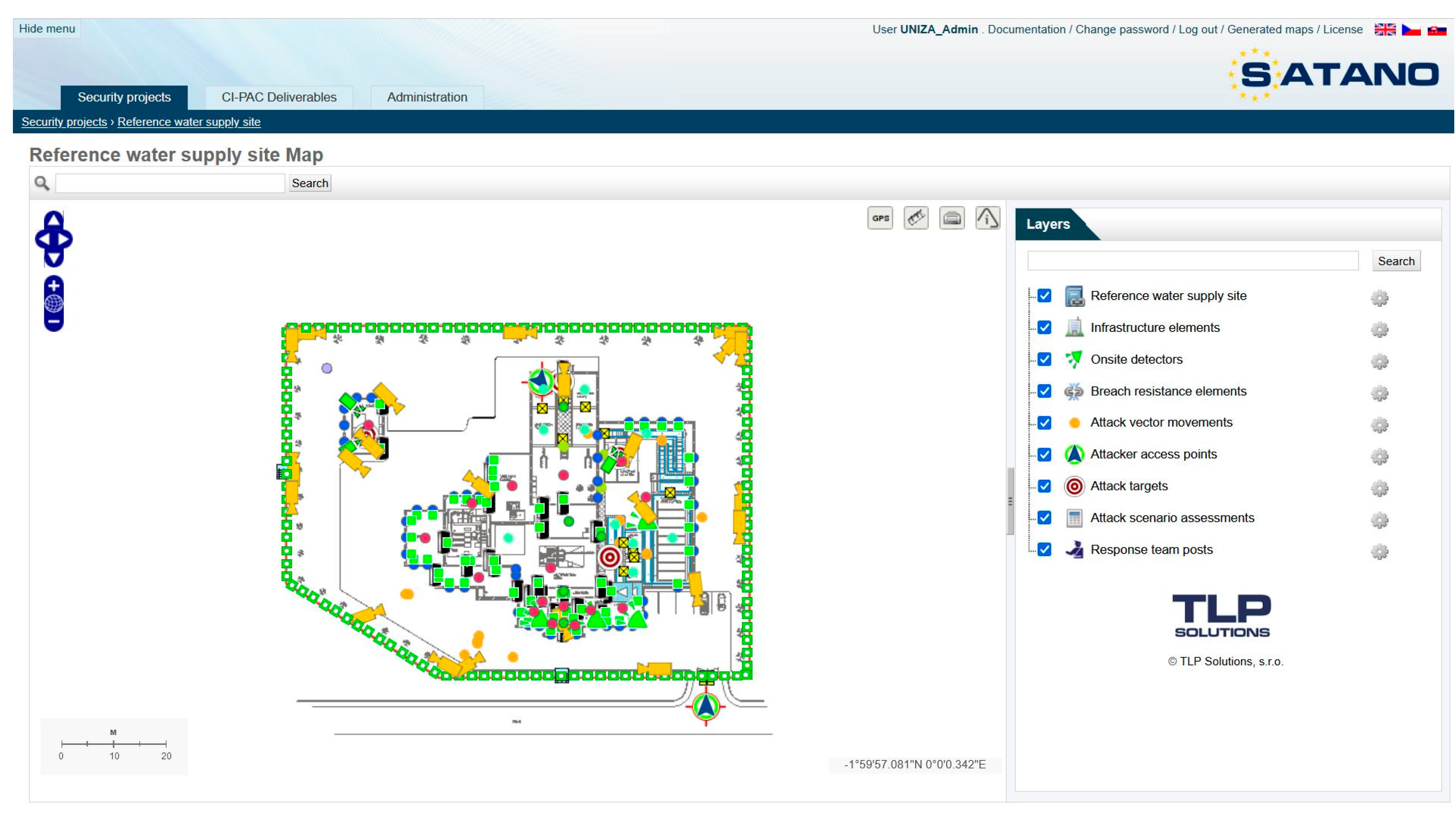
The SATANO (Security Assessment of Terrorist Attack in a Network of Objects) software tool, developed at the University of Žilina, in Žilina, is a simulation tool that allows users to quantitatively assess the level of PPS on various 2D-map documents (
Figure 1). The software tool was created as one of the outputs of the CI-PAC project: Critical Infrastructure Protection Against Chemical Attack (HO-ME/2013/CIPS/AG/4000005073).
The SATANO SW tool is based on the basic premise of system functionality, i.e., that it is necessary to use so many security measures that the intruder is detected and intercepted by the intervention unit before reaching their objective, which is considered to be damage to or destruction of the protected object of interest. The tool excludes any random influences that may interfere with intrusion into a protected area. The intruder is presumed to have all the necessary information on the protected object of interest (decided on the basis of certainty) and to know the shortest path to the protected object of interest, which is determined by the total time taken to breakthrough all barriers, including the times required for the transfer. This total time is calculated from the first point at which the intruder is detected by the alarm system (e.g., VSS).
In Annex No. 2 of Government Regulation No. 344/2006 Coll., one of the measures described is that in all tunnels with a control centre, video surveillance systems and a system capable of automatically reporting a traffic failure (such as stationary vehicles) or a fire are installed [
3]. The requirements for the design, implementation, operation, and maintenance of camera surveillance, the automatic traffic-incident detection (AID) system, and the automatic recognition system are defined in the methodological guideline TKP 40, defining the technical and qualitative conditions (TKP). In the case of tunnels, camera surveillance is part of tunnels’ safety equipment and is always connected to the central control system. Specifically, IP cameras are divided into [
18]:
security cameras in tunnels;
cameras designed to monitor traffic in tunnels;
cameras designed to recognise vehicle-registration numbers;
mini-dome or bullet cameras, installed in the escape corridors of tunnels.
The cameras designed to monitor traffic in tunnels are fixed in tunnel tubes and bays. Their main purpose is to monitor and evaluate the fluidity of traffic, or to monitor certain installations of technological equipment in tunnels. These cameras are always equipped with software for AIDs.
The surveillance cameras in tunnels are fixed or PTZ cameras, which are specifically installed in tunnel tubes, in escape and connection corridors, in technology rooms, and in other service areas of tunnels, such as boarding areas, entrances to areas with objects of interest, etc. Their main purpose is to monitor the movement of persons in escape and connecting corridors with a focus on the safe escape of persons from tunnel pipes, the protection of premises with technological equipment, etc. These cameras are not equipped with or connected to the AID module. The AID system allows lane tracking and evaluation at the same time [
19] in situations involving or requiring:
stationary vehicles;
driving in the opposite direction;
sudden drops in speed;
traffic-density monitoring for normal, dense, slow, congested, and stopping-and-moving traffic;
smoke in the tunnel;
pedestrians;
a dropped object on the road (e.g., lost cargo, etc.).
For the functionality of the AID system, the standard [
19] defines the minimum values of technical parameters such as the type of sensor, coding, minimum resolution, light sensitivity, number of frames per second, signal-to-noise ratio, backlight compensation, automatic white balance adjustment, AGC function, video-image detection, etc.
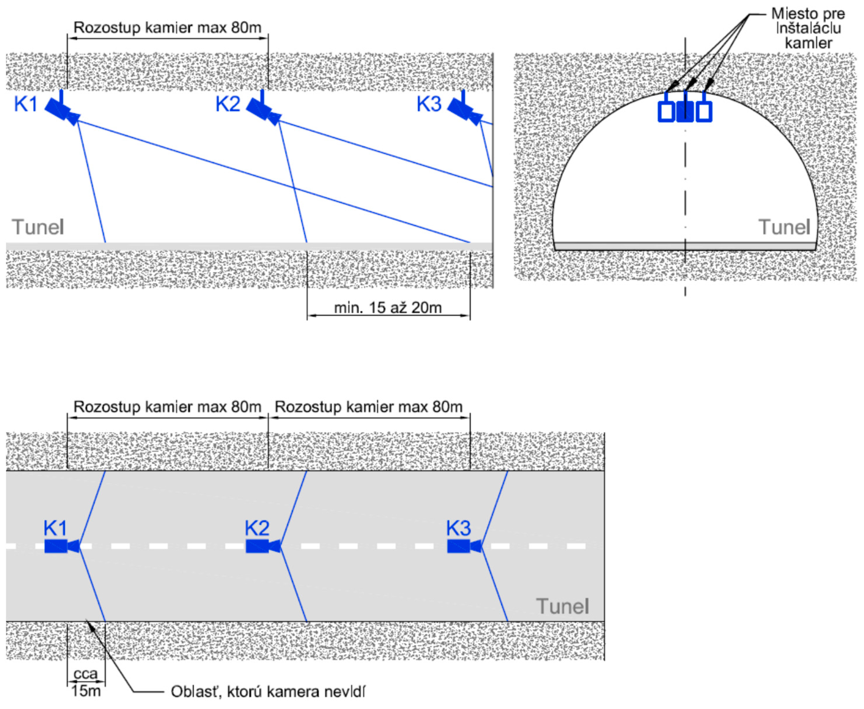
The cameras in tunnel tubes need to be positioned in such a way that the entire tunnel tube is covered by the camera footage, so that the camera footage includes all the entrances to escape corridors, bays, SOS cabinets, pavements, and access points to other technological equipment, without restricting the view of the passing cross-section. To this end, the design of the deployment of cameras is undertaken at the design stage, but only after all the other technological facilities are deployed.
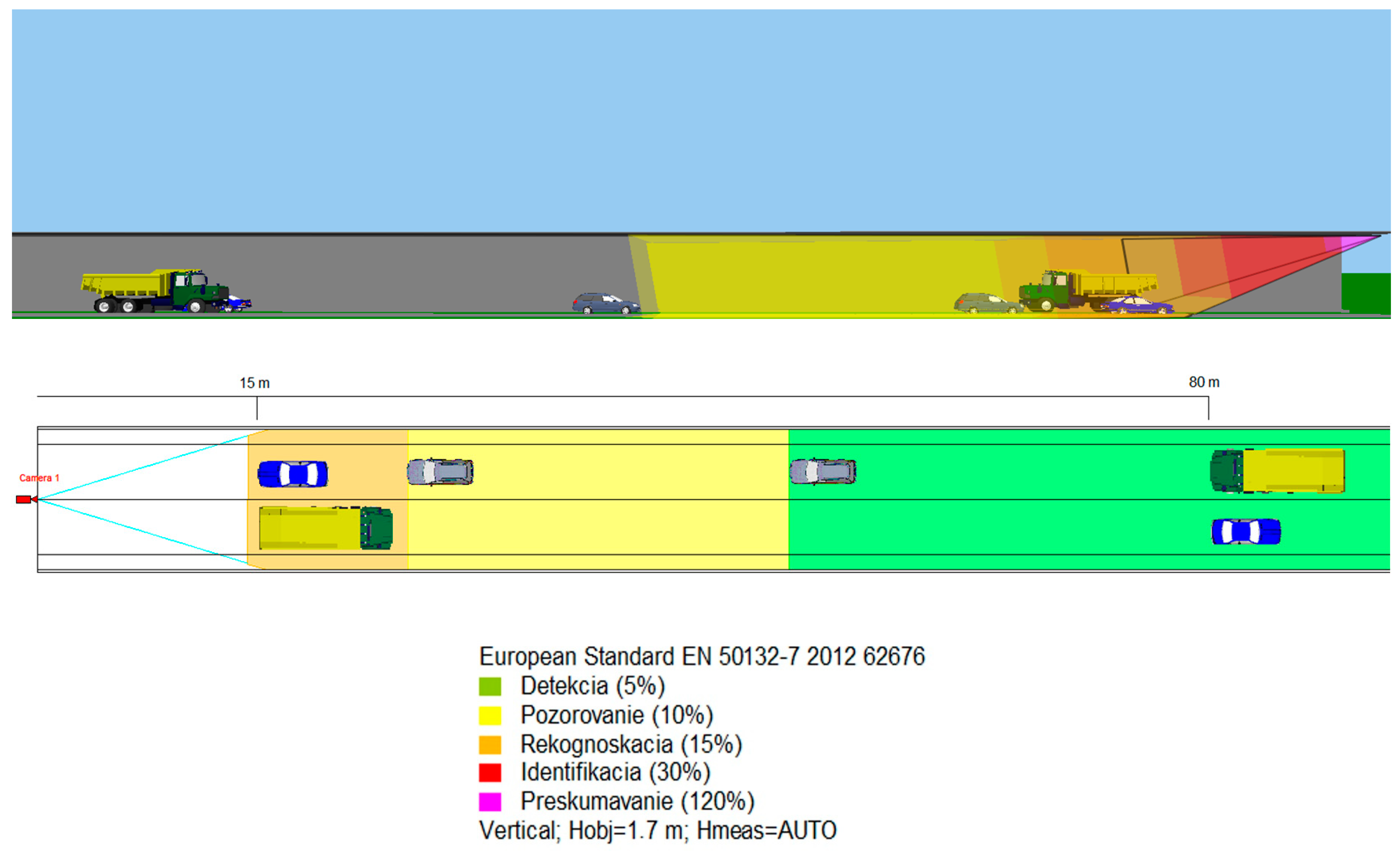
When deploying cameras for traffic evaluation in a tunnel, each camera is must have the subsequent camera in its frame, with an overlap of at least 15 m to 20 m. A maximum distance of 80 m between cameras is required (for a straight tunnel pipe). For arches, each camera must see the following camera with a sufficient overlap, of at least 15 m to 20 m, over the entire width of the tunnel tube (
Figure 2).
Figure 2 shows that the maximum distance between the two cameras is 80 m. However, it is not clear from the TKP 40 what the image quality will be at this distance. The image quality and/or application requirements of the camera system are defined by NOR EN 62676-4(16) (see
Table 2).
According to TKP 40, the operating temperatures of cameras should be in the range of −30 °C to +55 °C, and the cameras should be equipped with IP 66 enclosures [
19]. This requirement corresponds approximately to environment class III, according to EN 50130-5 and STN EN 62676-1-1 [
11,
20], which describes an outdoor environment protected from the direct influence of weather (e.g., rain, sun, etc.). The camera was tested at temperatures of −25 °C and +55 °C, at a relative humidity of 93%. At the same time, it must resist falling water droplets and the effects of sulfur dioxide.
Temperature fluctuations can cause problems not only for the human body but also for parts of electronic systems. Undoubtedly, these systems also include transport VSSs, which have to withstand extensive temperature changes throughout the year. In winter, the temperatures in some of the locations in which cameras are installed can reach as low as −20 °C. By contrast, in the summer period, under the influence of sunlight, the ambient temperature of a camera can be +35 °C and above. Different tunnel situations can cause situations in which VSSs are exposed to even greater temperature extremes (e.g., in tunnel fires). However, temperature is not the only influencing factor in the proper functioning of VSSs. The immediate surroundings of the camera are also of great importance. In the event that the camera is in a dusty environment, this dust can unpleasantly affect the proper functioning of the entire system.
3. Results
The overall minimum level of tunnel protection could be given by the minimum values of the output variables of the quantitative models, confirming the functionality of the entire protection system. The most frequently cited output variables of quantitative models include (
Figure 1):
The established minimum output values (e.g., the probability of eliminating an intruder must be greater than 0.95) indicate how many mechanical barriers with associated breakthrough resistance are to be implemented at the specified response time of the intervention unit. Furthermore, the minimum values of the output parameters indicate the probability of detecting an intruder by each element of the alarm system.
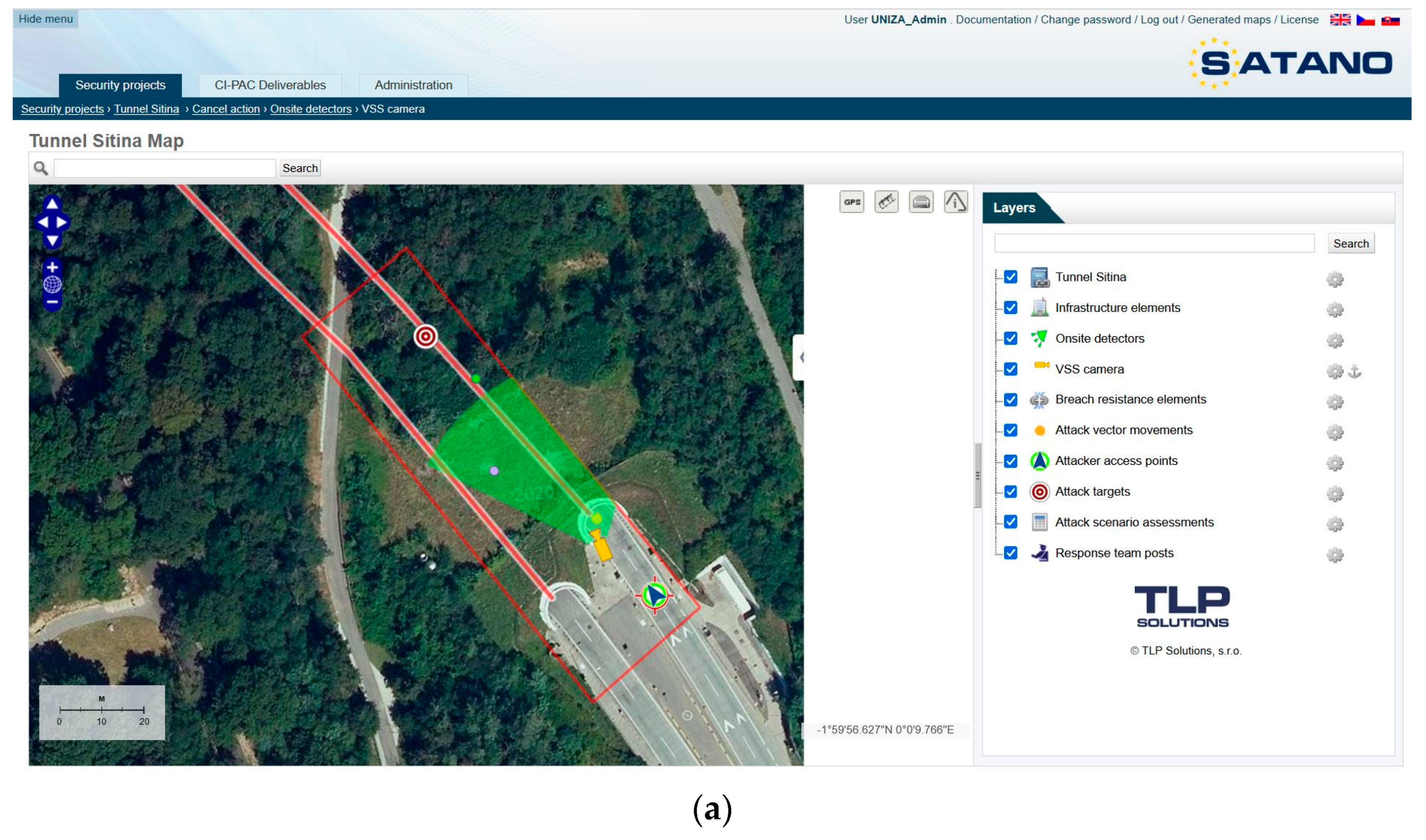
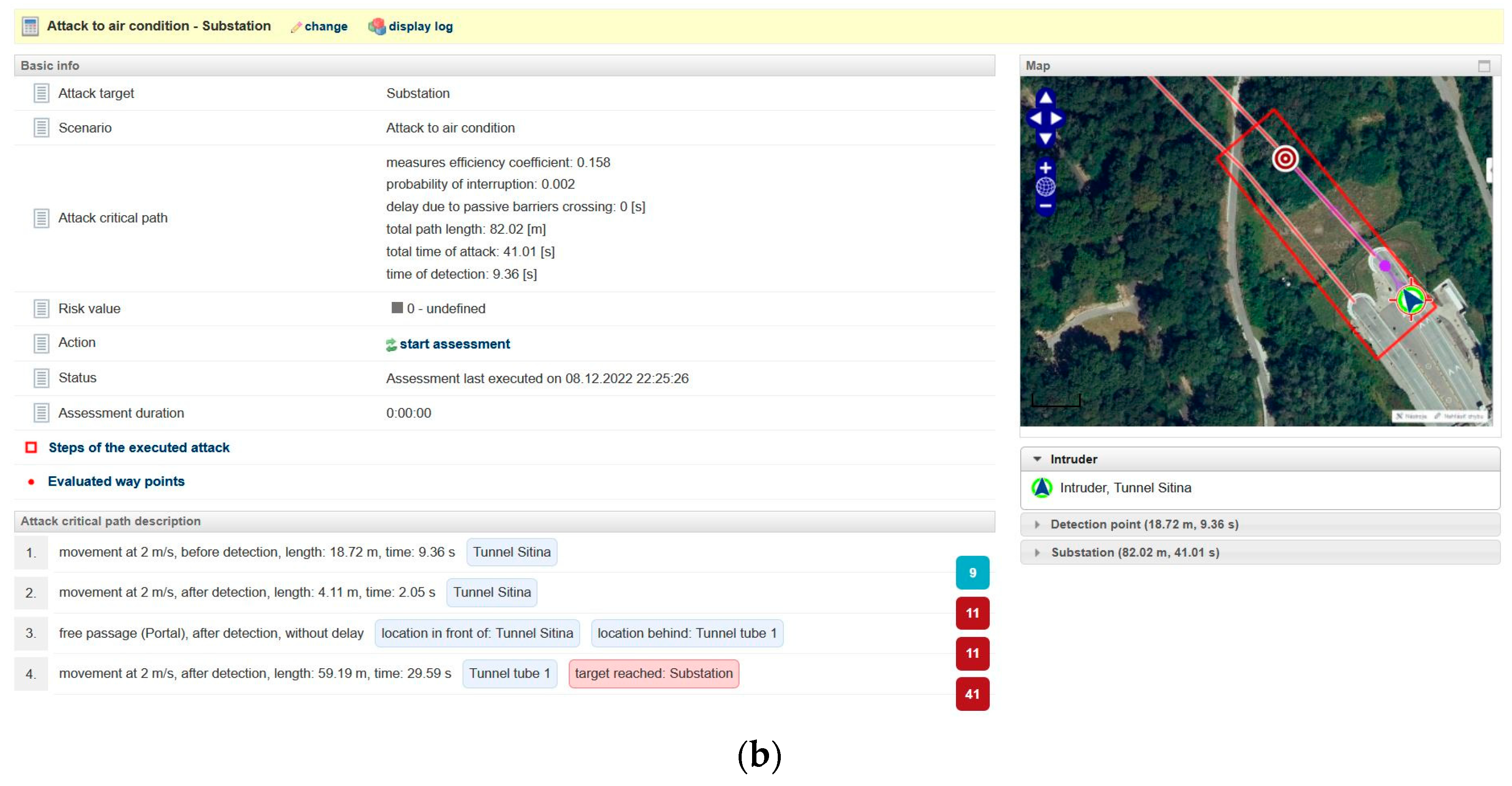
Figure 3 creates a model of a scenario involving unauthorised intrusion into the Sitina tunnel, followed by a simulation with the SATANO software tool. In this scenario, the intruder intended to pass through the tunnel’s entrance portal to the air-conditioning substation located in the central part of the tunnel; the intruder was detected by a security camera located at the entrance to the tunnel portal. The evaluation of the breach, as well as of the intervention itself, was carried out by the security services’ intervention unit. The results of the simulation show that if the time taken by the security services unit had been at least 600 s, it would not have been able to intervene against the intruder in time. The total time that an intruder would need from their detection by the VSS camera at the tunnel-entrance portal would be only 41 s, at an assumed average movement speed of 2 m/s. It follows from the above that it is necessary either to ensure the more timely detection of intruders or to increase the passive resistance of the air-conditioning substation.
From the point of view of the design of the VSS, it is important to determine the purpose of this alarm system, which may include, for example, monitoring, detection, and identification. According to TKP 40, only IP cameras with a CCD or CMOS sensing element (chip) with high resolution, i.e., 1080 p or higher, and with H.264 compression or better [
18] can be used in IP-camera surveillance. From the point of view of light sensitivity, the requirement at 30 IRE for light conditions is 0.1 (colour) or 0.01 (B&W) lux. At the same time, camera functions, such as day and night vision, noise reduction (S/N) (>50 dB), wide dynamic range (>60 dB), or backlight compensation, are required.
Figure 4 shows a model for capturing a camera in tunnels simulated using the IP Video Design Tool. The camera’s parameters, such as height, tilt, resolution, and camera-sensor size, were specified according to regulations [
19].
Figure 4 shows that cameras in the range of 15 to 80 m (standardised according to TKP 40) are only capable of motion detection (up to 46% of the scene being shot), which meets the standard to EN 62676-4 [
16], according to which only the presence of a person or object can be detected. In the case of the requirement to implement smart solutions (e.g., Intelligent Video Analytics), through which it would be possible to automatically recognise not only the presence of persons in a given space, but also their non-standard behaviour, the scene captured should not fall below the level of observation (more than 16 mm of the captured scene per pixel, i.e., 62.5 px/m) or recognition (more than 8 mm of the captured scene per pixel, 125 px/m). By modelling the ability of the camera to sense non-standard behaviour in the tunnel, using the IP Video Design Tool software tool, it is possible to conclude that the maximum distance between two cameras should therefore be reduced to at least 50 m (it is currently up to 80 m, in accordance with TKP 40), or the minimum camera resolution should be increased (e.g., a camera with a minimum resolution of 5 Mpx).
As mentioned above, extreme temperatures can have an impact on smart technologies installed in tunnels (e.g., VSS). These transport VSSs must withstand extensive temperature changes during the year, which are caused by the natural environment or by emergency situations (e.g., car fires). As part of the project, SMART TUNNEL: Telematic support for emergencies in the traffic tunnel (APVV-17-0014), transport VSS were tested against extreme temperature changes. Extremely high and low temperatures were created using the VÖTSCH VCL 7010 climate chamber, which can create temperatures in a range from −70 °C to +180 °C. According to EN 50130-5, the lowest temperature considered is −25 °C [
20], which is sufficient for the local conditions of Slovakia. From the point of view of the load on the cameras in the tunnels, it is relevant to monitor the exposure of the cameras to high temperatures. The limit value was the temperature at which the camera stopped working properly or completely.
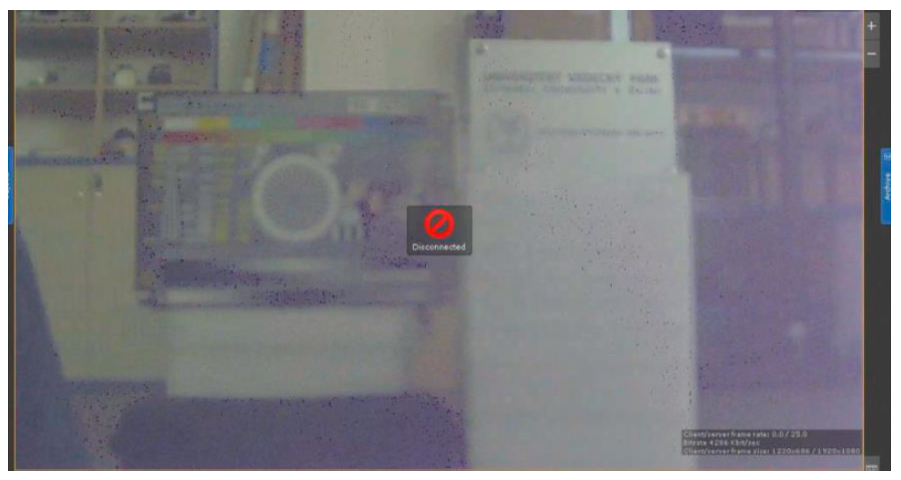
The subject of the test in the climate chamber was a selected camera system from the company, DYNACOLOR. The camera is of environment class 3, which means that its recommended operating temperature range from −10 °C to +50 °C, at a humidity level below 90%. To evaluate the image quality, the CCTV Test Chart was placed in the field of view of the camera at a distance of 2 m. The temperature was gradually raised to the level of +180 °C. The temperature of +152 °C (
Figure 5) was the temperature ceiling for the tested camera, which means that the camera stopped fully communicating and sending data to the output-imaging control at this temperature. This measurement showed that the temperature specified by the manufacturer may not always be the limit temperature.
Further investigations revealed whether this caused irreversible damage to the camera. The last measurement was taken from a temperature of 152 °C to a temperature of −70 °C, which was the lowest temperature created in the climate chamber. The image of the camera was partially restored at 30 °C. A further investigation was carried out to determine whether there was irreversible damage to the camera. The last measurement was taken from a temperature of 152 °C to a temperature of −70 °C, which was the lowest temperature created in the climate chamber. The image of the camera was restored at a temperature of 30 °C, at which point the camera began to communicate again. However, there was partial permanent damage to the camera. Subsequently, the signal from the camera was lost at a temperature of −65.5 °C.
Another research task was to determine whether the above-mentioned critical value above 150 °C could be reached in tunnels in the event of a fire, which is the most likely emergency scenario in tunnels. A simulation was carried out using the software program, Fire Dynamics Simulator, and the subsequent images were displayed in Smokeview. As part of the simulation, all the parameters of the TKP 40 detected and projected so far were observed [
18], in particular the camera pitch, with a maximum length of 80 m. For this reason, a 129-m-long tunnel pipe with a usable area of 38.34 m
2 was used for simulation purposes, and the simulation took place in the direction of the wind. The aim of the simulation was to determine the time t, the value of which indicates at what point in time, in selected types of fire, a critical temperature occurs that threatens the functionality of the camera. The simulation was carried out while maintaining two basic conditions, namely with and without automatic extinguishing equipment (AEE). Within the source of burning, three variants were considered, namely a passenger car (5 MW), a van (15 MW), and a truck (30 MW). The time results of the simulations are shown in
Table 3. The expression of the time required for the formation of critical temperature with and without the use of AEE was made in order to improve safety in road tunnels. According to TP 13/2015, the spaces in tunnel tubes and emergency bays may be equipped with AEE; if necessary, this may be undertaken as a result of a tunnel-safety-risk analysis [
22]. The AEE with water mist was chosen because of its good results in many European countries. This type of system is installed in tunnels under the River Tyne, in Newcastle.
The data in
Table 3 show that a critical value of 150 °C was measured at certain outputs and distances. This fact also depends on the used AEE, thanks to which, directly above the fire, a critical temperature arose only for a few seconds, which did not mean damage to the camera.
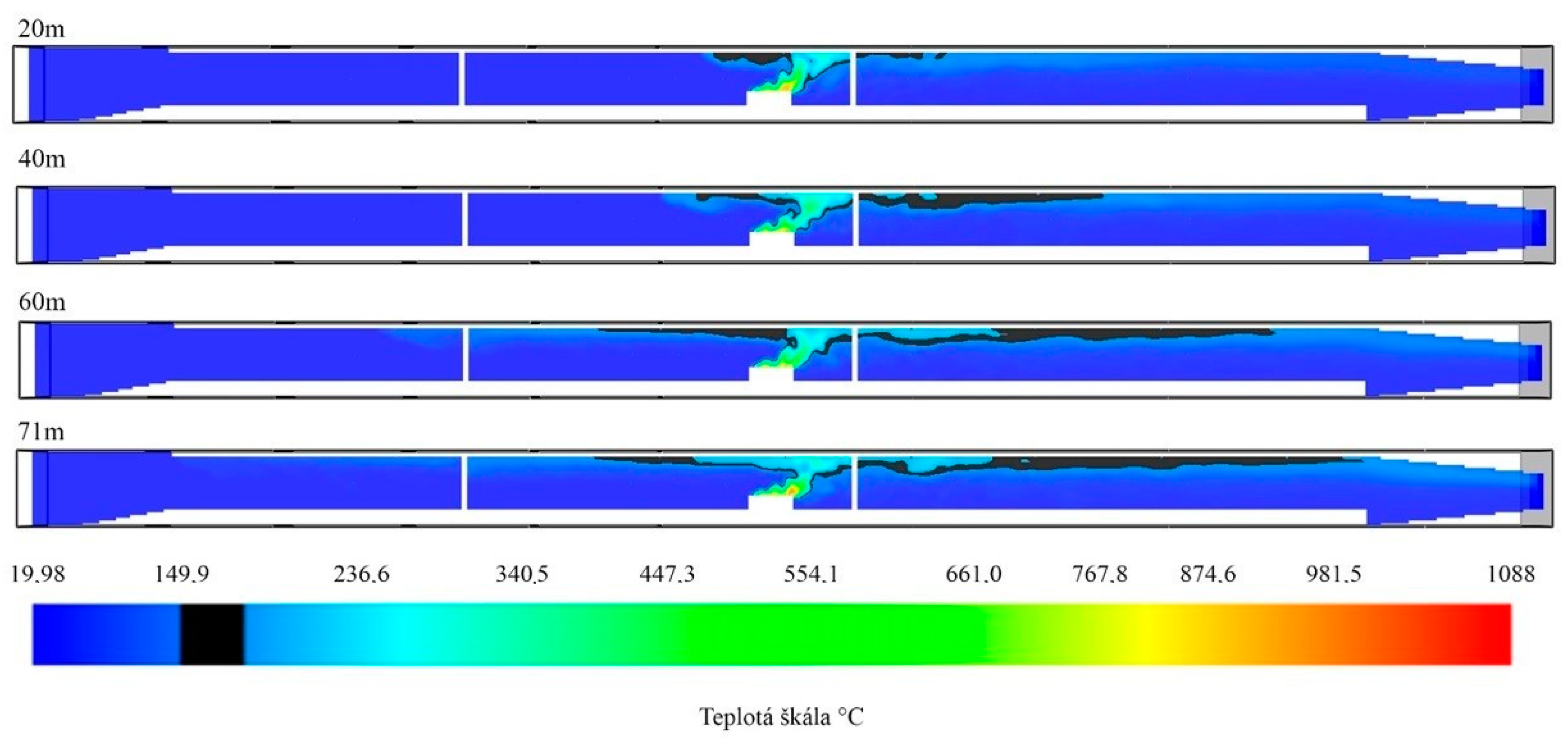
Figure 6 shows the temperature patterns for 5 MW.
As mentioned above, using AEE, a critical value was measured only at a certain point (90.9 s), but only for a very short time (0.3 s), directly above the source of burning. A view of the simulation at 90.9 s is shown in
Figure 7.
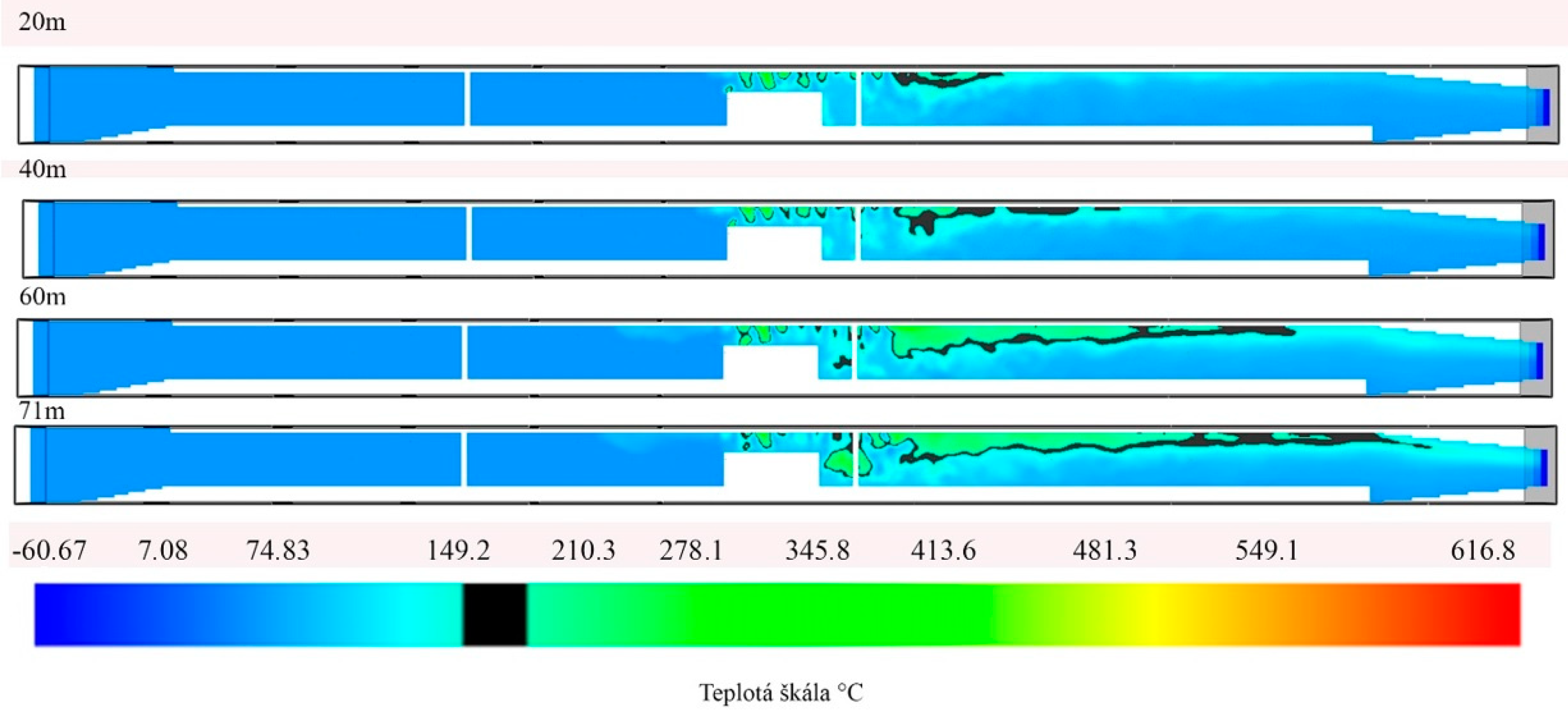
According to
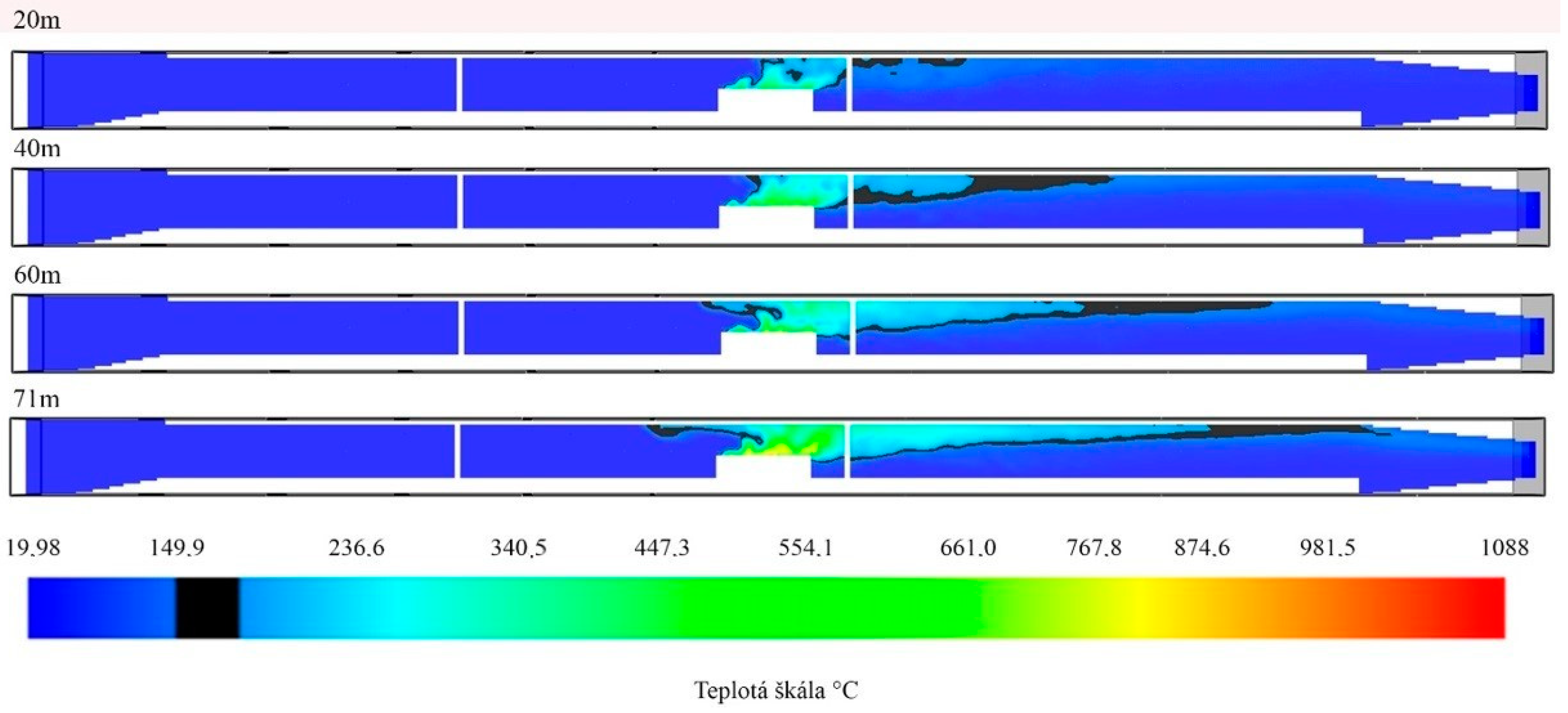
Table 3, with a heat source of 15 MW, similar results were achieved. With the AEE used, a critical temperature of 615.6 s was reached for a short time, but only at a distance of 20 m. The results obtained are shown in
Figure 8 and
Figure 9.
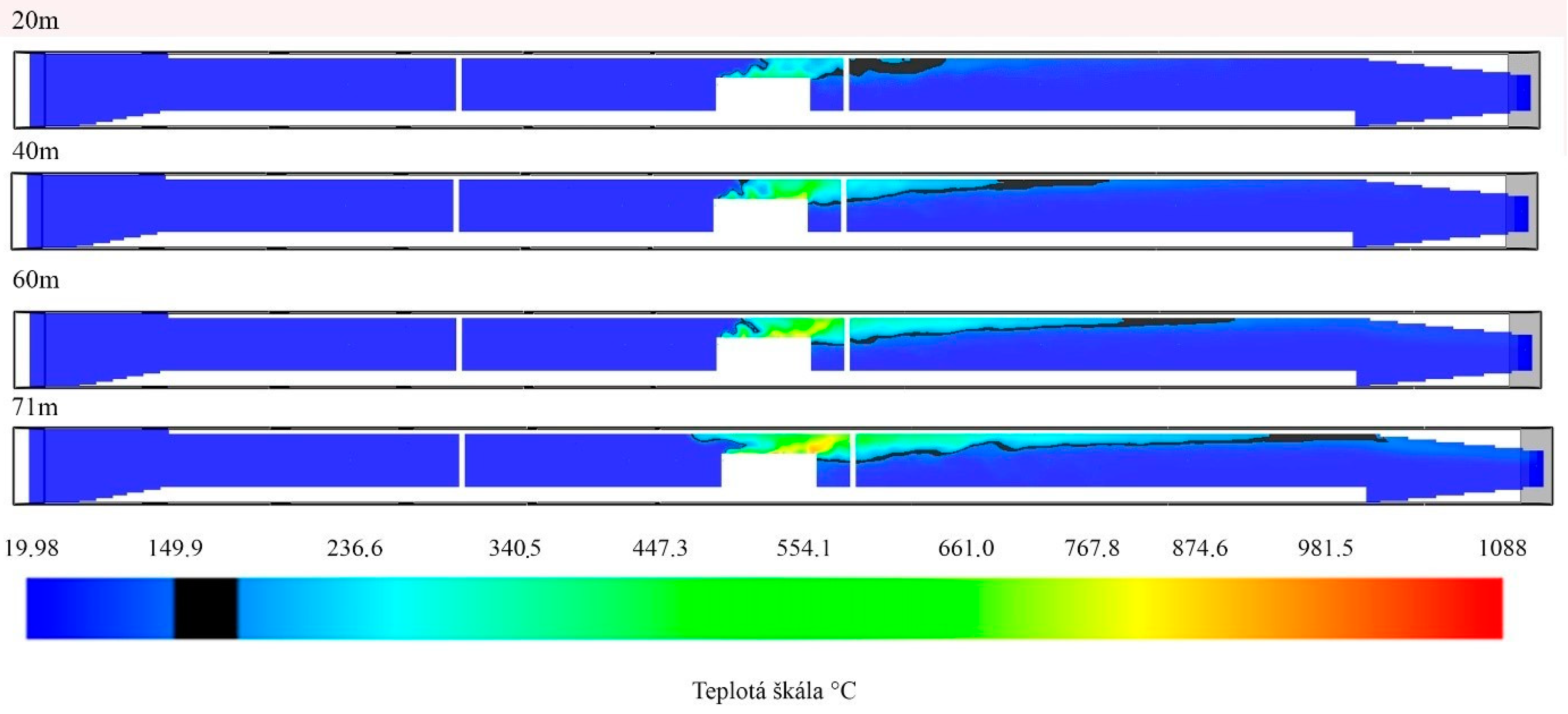
The only option in which the critical temperature was recorded even when the AEE was used was a heat source of 30 MW, which corresponded to the burning of the truck. The results of the simulations are shown in
Figure 10 and
Figure 11.
The above measurements under laboratory conditions created the starting conditions for testing the cameras in real road-tunnel conditions. A critical temperature of 150 °C was established, which had a fatal effect on the operation of the camera. Subsequently, using the software tool, Fire Dynamics Simulator, we determined the selected distances (20, 40, 60, and 71 m) at which the critical temperature of 150 °C in the immediate vicinity of the camera would be reached. A significant finding was that when using AEE with water mist in tunnels, this time was significantly increased or eliminated altogether. Based on the above, it can be concluded that, in addition to having a direct impact on fire safety in road tunnels, AEE also has an impact on the operational capacity of VSSs in tunnels.
4. Discussion
Video Surveillance Systems (VSSs) are integral parts of road-tunnel-security and -safety systems. They currently perform a number of functions, such as ensuring the protection of tunnel technologies, monitoring tunnel traffic, or recognising vehicle-license plates. With the development of new technologies, it is assumed that VSSs will also be used in the future for smart solutions, which will be based on the intelligent video analysis of images. This makes it necessary to assess whether the currently proposed standards for the design of VSSs in road tunnels comply with these new requirements.
Currently, one of the primary tasks of VSS systems is to protect tunnels and their technologies from unauthorised intentional human activity. Here, it is necessary to ensure that the entire physical protection system (PPS) is designed in such a way that the basic requirement for its functionality is met. When it is necessary to objectively assess whether this requirement has been met in the design of the PPS, it is appropriate to use one of the software tools enabling the quantitative evaluation of PPSs, based on measurable output variables (e.g., the probability of intruder elimination). In the article, using the example of tunnel-intrusion simulation, a new tool, SATANO: Security Assessment of Terrorist Attack in a Network of Objects, was presented; this tool makes it possible to evaluate whether the proposed PPS allows an effective response time from the intervention unit, measured from the at which the VSS detects the intruder at the entrance to the tunnel portal. This SW tool has also been applied to other types of object [
23,
24].
Video surveillance systems enable multiple applications, such as monitoring, detection, recognition, and identification. This article assessed the current standardised requirements for the design of a VSS in a tunnel from the point of view of its possible use for intelligent video analysis, allowing the recognition of various risk situations (e.g., non-standard driver behaviour). To assess the current standardised requirements, the IP Video Design Tool software was used, which made it possible to model the possibilities or limits of using the applicable standard. From the results of the investigation, it can be concluded that at present, VSSs are only capable of motion detection (up to 46%) in a substantial part of the scene being scanned. In the case of the request for the implementation of intelligent video analytics, through which various non-standard behaviours or situations can be automatically recognised, it is necessary either to reduce the spacing of cameras from the current 80 m to a maximum of 50 m, or to increase the requirement for the minimum resolution of cameras from 1 to 5 Mpx [
24,
25,
26].
In the event that there is a requirement to use the VSS during emergency situations (e.g., a fire in a tunnel), it is necessary to determine the operating conditions and period of time through which the VSS would operate in a given tunnel. The article presented the results of experiments aimed at testing the reliability of cameras in extreme temperature conditions. Subsequently, the results of the simulation of the spread of fire in the tunnel and its possible impact on the operation of the VSS were presented. From the results of the experimental tests, it can be concluded that the reliability of the cameras far exceeded the specified operating ranges (50–55 °C), and the critical limit was around 150 °C. In the event of a fire in the tunnel, this limit temperature would be reached without AEE (e.g., sprinklers) in the order of minutes (depending on the source of combustion, e.g., a passenger car, van, or truck), thus rendering the VSS inoperable. In certain circumstances, depending on the heat source, even AEE would not prevent damage to the cameras.
From the point of view of the modelling and simulation of PPS tunnels, further research is required to obtain a data set with the real values of input variables by using experimental measurements (e.g., the probability of intruder detection, or reaction time by intervention unit) or software simulations (e.g., the breakthrough resistance of a mechanical barrier). At the same time, in the event of the completion of research into the possibility of using VVS in tunnels from the point of view of operating conditions, further research should address possible scenarios involving the non-standard behaviour of drivers in the tunnel.


