Article

Numerical Simulation of Assembly Process and Sealing Reliability of T-Rubber Gasket Pipe Joints

1
College of Civil Engineering, Kashi University, Kashi 844008, China
2
College of Civil Engineering, Henan University of Technology, Zhengzhou 450001, China
3
School of Civil Engineering, Tianjin University, Tianjin 300354, China
4
Zhengzhou Institute of Industrial Technology, Zhengzhou 451150, China
5
China State Construction Engineering Co., Ltd., Nanjing 210049, China
*
Author to whom correspondence should be addressed.
Sustainability 2023, 15(6), 5160; https://doi.org/10.3390/su15065160
Submission received: 22 February 2023 / Revised: 11 March 2023 / Accepted: 13 March 2023 / Published: 14 March 2023

Abstract

:
Underground pipelines are vital parts to urban water supply, gas supply, and other lifeline systems, affecting the sustainable development of cities to a great extent. The pipeline joint, which is a weak link, may be seriously damaged during natural disasters such as earthquakes. The failure of pipe joints can cause leakage accidents, resulting in system failure and interruption, and even some secondary disasters. Herein, based on uniaxial and plane tensile test results of a T-rubber gasket material, the assembly process and sealing performance of a T-rubber gasket joint of a ductile iron pipe are numerically simulated using the Ogden third-order strain energy density function to fit the material constant. The simulation accounts for severe nonlinearities, including large deformations, hyperelasticity, and complex contacts. The effects of the assembly friction coefficient, assembly depth, and radial clearance deviation of the socket and spigot on the seal contact pressure are analyzed. The results suggest that the entire history of the deformation and stress variations during assembly can be clearly visualized and accurately calculated. For the different friction coefficients, the assembly depth corresponding to the sliding friction condition of the spigot pipe was 74 mm, while the minimum pushing force required to assemble the T-rubber gasket joint of a DN300 ductile iron pipe was 6.8 kN at the ideal situation with a friction coefficient of 0. The effective contact pressure of the rubber gasket seepage surface under various operating conditions is much higher than the normal pressure of municipal pipelines, thus indicating that the rubber gasket joint exhibits the ideal sealing performance. Furthermore, a certain deviation, which is about 20 mm, is allowed for the assembly depth of the rubber gasket joint such that the axial displacement of the pipe joint can be adapted under an earthquake or ground displacement.

1. Introduction

Underground pipelines are vital to urban water supply, gas supply, and other lifeline systems, and are important part of the infrastructure ensuring sustainable development of a city. For a sectional connection pipeline, the pipeline joint is a weak link, while joint damage is the primary failure mode under the action of various disasters, i.e., earthquakes and geological disasters [1,2]. Recently, rubber gasket joints have been widely used in urban water supply, gas supply, and other pressure pipelines, as well as long-distance oil pipelines and super-large-diameter water pipelines, owing to their good adaptability to various deformations. The cost of a rubber gasket, a key component in the sealing of pipe joints, accounts for only 1% of the pipeline cost; however, its failure can cause leakage accidents, thus resulting in system failure and interruption, which may cause water pollution, explosions, and other severe secondary disasters.
Rubber is well recognized as a hyperelastic material with a low elastic modulus, high stretchability, and high energy storage capability. A rubber gasket undergoes significant shape changes during the assembly of the pipe joint, as well as intense extrusion and friction with the spigot and socket. Its mechanical analysis is highly complicated as it involves geometrical, physical, and boundary condition nonlinearities. Therefore, when analyzing the mechanical properties of the rubber gasket, the hardness and elongation of the rubber as well as the compression rate of the rubber gasket after assembly are typically used as control indicators. Nonetheless, refined analyses of the large deformation, stress state, and sealing performance of rubber gasket materials are limitedly conducted. The design of rubber gasket joints and the gaskets of various pipelines is based primarily on experience and a few tests [3,4]. Generally, the rubber gasket is accepted once it does not leak in the required tensile displacement or deflection angle tests. This acceptance criteria lacks theoretical support when designing for pipes located in poor ground environments or that may suffer strong earthquakes, which does not meet the sustainability requirements of a pipe for long-term service.
With the development of computer simulation technology and modern nonlinear theories, the finite element analysis method has been applied to the analysis of rubber components with various forces, constraints, and complex shapes. In recent years, numerical simulation studies pertaining to the use of rubber seals in aerospace and mechanical fields have been extensively performed [5,6,7,8,9,10]. Regarding municipal pipelines, Theiner et al. [11] developed a simpler axisymmetric FE model of the joint for pipe systems under high operating pressures, and evaluated the preliminary design of the joint through numerical simulation. Zhong [12] performed finite element modelling in ANSYS to analyze the contact pressure of a double O-rubber gasket for DN3000 Prestressed Concrete Cylinder Pipe (PCCP) pipelines and determine the effects of manufacturing accuracy, pipe settlement, and other factors on the sealing capacity of the gasket joint. Wang et al. [13] established a three-dimensional numerical model of a socket drainage pipe using the ABAQUS finite element software and analyzed the effects of pulse amplitude, load location, and depth of burial on the dynamic response of the pipe under traffic loads. Dong et al. [14] studied restrained joint and pulling load for ductile iron pipe in horizontal directional drilling, in which the finite element method (FEM) was used to study the mechanism of joint failure as well as the effect of slope angle. As test data regarding the basic mechanical properties of rubber materials are not available, most researchers typically use Treloar’s experimental data [15] or the low-order Mooney–Rivlin model to determine the material constants when performing a numerical analysis of the sealing properties of rubber gaskets. However, Treloar’s basic mechanical property test of rubber, which is classical, was published in 1944, the results of which are not applicable to all rubber materials. Indeed, the constitutive relation of the model may differ significant from the actual mechanical properties of the rubber gasket owing to the different components of the rubber and the production process. Meanwhile, the low-order Mooney–Rivlin model, whose model parameters can be obtained easily, is only a low-order function, indicating that it is difficult to accurately predict the complex deformation behavior of rubber materials. Hence, the characteristics of the problem investigated can be reflected objectively only by fitting the corresponding constitutive mode with the experimental data of rubber materials.
Existing finite element analyses of the sealing performance of rubber gaskets do not sufficiently consider the gasket installation, pipe joint assembly process, and historical cumulative state of the sealing rubber gasket. To ensure that the pipe joint achieves high-quality sealing, the initial outer diameter of the T-rubber gasket is designed to be slightly larger than the inner diameter of the socket clamping groove. In the actual installation process, after the rubber gasket is placed in the clamping groove, a radial force must be applied to ensure its tight fit with the clamping groove. Thus, before the spigot is assembled, the rubber gasket has been subjected to a certain amount of initial stress. This guarantees the smooth assembly process of the pipe rubber gasket joint as well as its high-quality sealing after the assembly. However, owing to the limitations of the numerical method, the details above have rarely been considered in existing studies.
Compared with experimental studies, numerical simulations require fewer cycles and incur lower test costs, which is conducive to the realization of sustainable design. Owing to the small structural dimensions of the rubber gasket and the opaqueness of the pipe material, the changes and evolution of the deformation, stresses, and contact stresses of the rubber gasket during the assembly of the pipe joint are difficult to observe and measure.
In this study, to simulate the assembly stress and sealing performance of the rubber gasket joint, the T-rubber gasket joint of a DN300 ductile iron pipeline, which is typically used in municipal engineering, was selected. The basic mechanical properties of the rubber material and the material constant fitting of the third-order Ogden model were analyzed. The interference fit and assembly process of the rubber gasket joint were simulated. Additionally, the sealing performance of the rubber gasket joint and the influencing mechanisms of different factors are discussed herein. The relevant modeling and research results can provide a reference for the design of flexible joints and sustainable design of rubber-like components.

2. Computational Model

2.1. Model Parameters

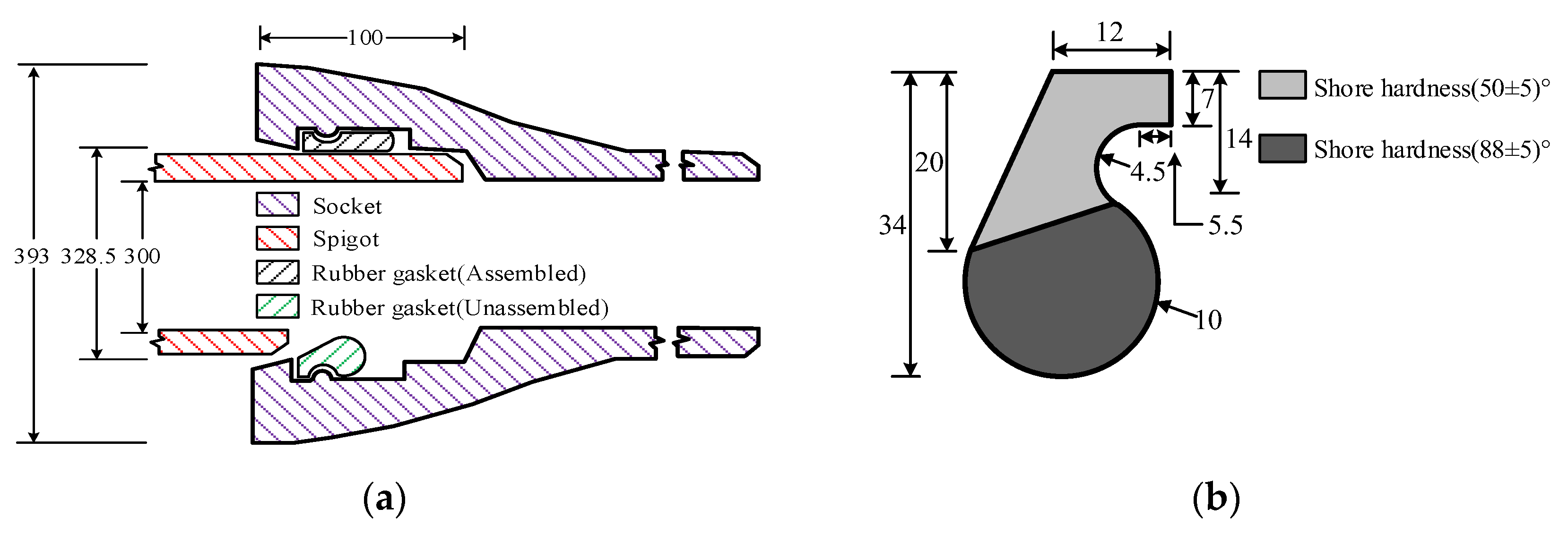
The research object of this study was a ductile iron pipe rubber gasket joint typically used in municipal engineering. The calculation model prototype, a DN300 socket-type ductile iron pipe (produced by Xinxing Casting Pipe Group Limited, Wu’an, China), was selected based on the national standard [16]. The nominal diameter of a DN300 socket type ductile iron pipe is 300 mm, including a pipe socket, pipe spigot, and sealing rubber gasket, as shown in Figure 1a. The rubber sealing gaskets used in this study were based on a T-rubber sealing gasket with Shore hardness values of 50 and 88, as shown in Figure 1b. The calculated dimensions are shown in Figure 1. Based on the national standard [16], the assembly depth of the pipe socket was set to 100 mm.
The simulation was performed using commercial finite element software ABAQUS. Because the T-rubber gasket joint is an axisymmetric component, the load and deformation of the rubber gasket in the joint assembly process under ideal conditions are axisymmetric; therefore, the model is regarded as axisymmetric. A CAX4H axisymmetric quadrilateral unit was used to simulate the T-rubber gasket and was supplemented by a triangular unit for transition, as shown in Figure 2. The ductile iron pipe was assumed to be a rigid body owing to its high stiffness compared with that of the rubber gasket.
Two contact surfaces were set between the rubber gasket and socket and between the rubber gasket and spigot to define the normal contact and tangential friction behavior between them. In the actual construction process, the outer surface of the rubber gasket was coated with lubricant before the assembly of the rubber gasket joint to facilitate the installation of the spigot. The friction coefficients of a ductile iron pipe and rubber gasket were 0.85–1.05, while the friction coefficients were 0.1–0.5 after the lubricant was applied [17]. Herein, to simulate the actual installation conditions of the rubber gasket joint, the coefficient of friction μ between the T-gasket and socket (without lubricant) was set to 0.95, whereas the coefficient of friction μ0 between the rubber gasket and spigot (with lubricant) was assumed to be between 0–0.3.

2.2. Constitutive Parameters of T-Rubber Gasket Materials

Rubber materials are typically regarded as hyperelastic materials, and their stress tensor can be described by the derivative of the strain energy density function with respect to the strain tensor. Scholars have proposed several hypotheses regarding the strain energy density function of rubber-like materials. In this regard, the most representative models used are the Mooney [18], Rivlin [19], Ogden [20], Yeoh [21], and Gent [22] models. As each of these strain energy models are based on specific assumptions or experiences [23,24,25], they do not predict the complex deformation behavior of rubber-like materials in the same manner. When evaluating the constitutive model of hyperelastic materials, the Ogden third-order strain energy function has been shown to yield better simulation results pertaining to the multi-axial deformation behavior of rubber when both uniaxial tensile (UT) and plane tensile (PT) test data are applied [26,27].
The Ogden third-order strain energy function [20] is expressed as shown in Equation (1).
W = i = 1 N μ i α i ( λ 1 α i + λ 2 α i + λ 3 α i 3 )
where αi and μi are arbitrary material constants; λi is the principal elongation ratio (i = 1, 2, and 3); and λ1λ2λ3 = 1 when considering the isotropic and noncompressible characteristics of rubber.
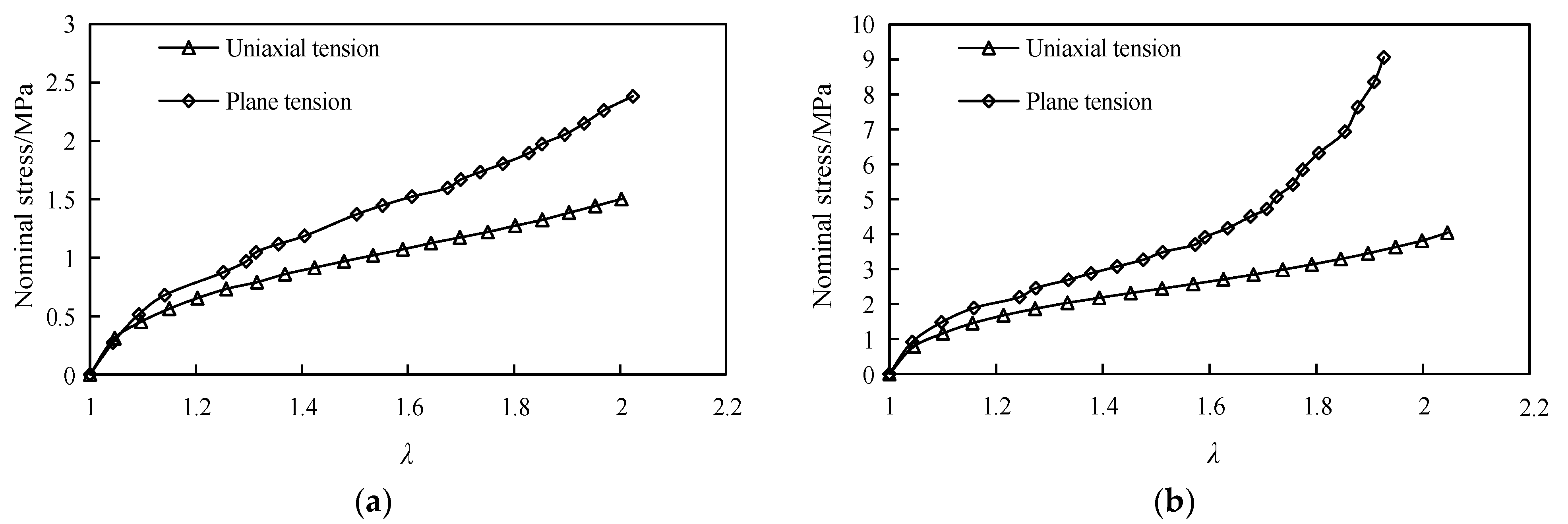
To determine the basic mechanical properties of the T-rubber gasket to be used for ductile iron pipe joints, two types of rubber specimens with Shore hardness values of 50 and 88 were fabricated and subsequently subjected to UT and PT tests, as shown in Figure 3.
The relationship between nominal stress σ and axial elongation ratio λ based on the deformation process of the two types of rubber materials with Shore hardness values of 50 and 88 is shown in Figure 4.
For the two types of rubber materials, their elongation ratio in each direction during the deformation process can be described as shown in Equation (2).
UT : λ 1 = λ , λ 2 = λ 3 = λ 1 / 2 PT : λ 1 = λ , λ 2 = 1 , λ 3 = λ 1
where λ is the axial elongation ratio of the two rubber materials.
For a strain energy density function W, the Cauchy principal stress ti (i = 1, 2, and 3) corresponding to the elongation ratio λi can be expressed using Equation (3).
t i = λ i W λ i p
where p is the hydrostatic pressure.
Combining Equations (2) and (3), the relationship between the nominal axial stress σ and axial elongation ratio λ based on UT and PT tests can be obtained, as shown in Equations (4) and (5), respectively.
σ UT = i = 1 N μ i ( λ α i 1 λ 1 2 α i 1 )
σ PT = i = 1 N μ i ( λ α i 1 λ α i 1 )
Based on the equations above and the UT and PT test results in Figure 4, the material constants were globally fitted using the least-squares method. A comparison between the fitting and test results is shown in Figure 5, and the obtained material constants, αi and μi, are listed in Table 1.
The results shown in the graphs reveal that the Ogden model (N = 3) predicted the deformation history of rubber materials with a Shore hardness of 50 more closely. Moreover, for the prediction of rubber materials with a Shore hardness of 88, the UT test results were more similar to the fitted results compared with the PT results. In terms of the PT test, although the predicted results were underestimated compared with the fitting results when the main elongation ratio λ exceeded 1.7, the results maintained an ideal fitting when the elongation ratio was less than 1.7. As the peak elongation ratio λ of a T-rubber gasket under actual working condition is generally less than 1, the fitting parameters satisfied the simulation accuracy of the assembly process of the pipe rubber gasket joint.

2.3. Simulation Scheme

The pseudo-static method was applied to closely model the actual operating condition of the assembly process of the pipe T-rubber gasket joint. Three static analysis procedures were established to simulate the installation of the rubber gasket, installation of the joint, and hydrostatic test, as follows.
Step 1: A sealing rubber gasket was installed in the socket. The socket was uniformly heated and expanded to match the size of the rubber gasket (the groove circumference of the socket expanded from 356.5 to 366 mm). Subsequently, the rubber gasket was installed, and the socket was cooled uniformly to the actual size of the socket groove (the groove circumference decreased from 366 to 356.5 mm) to model the annular extrusion of the rubber gasket. The rubber gasket was tightly fitted with the socket groove to generate the initial assembly stress in the rubber gasket.
Step 2: A spigot was pushed into the fixed socket for assembly. Particularly, the spigot was pushed into the socket at a uniform speed along the axial direction of the pipe and then assembled to a standard installation depth of 100 mm. The friction coefficient between the spigot and rubber gasket was assumed to be 0.15.
Step 3: A hydrostatic test was performed by changing the friction coefficient between the spigot and rubber gasket to 0.95 (to simulate the dry failure of the lubricant after pipeline assembly). Subsequently, the water pressure supply was increased to simulate the normal operating state of the pipeline rubber gasket joint.

3. Results

Figure 6 shows the von Mises stress cloud plot for the installation of the T-rubber gasket in Step 1. As shown in Figure 6, as the diameter of the socket continued to reduce to the actual size, the rubber gasket and socket groove tightened gradually, and the deviatoric stress increased slowly, thus resulting in significant changes along the interface of the two types of rubber. This indicates that (i) the T-rubber gasket was subjected to a certain initial assembly stress after installation was completed, (ii) the subsequent socket assembly was completed based on the initial assembly stress, and (iii) a certain historical accumulation of rubber gasket deformation occurred.
Figure 7 shows the assembly process of the socket and spigot in Step 2 of the analysis (assuming that the friction coefficient between the outer surface of the T-rubber gasket and the spigot was 0.15 after the lubricant was applied). Figure 8 shows the relationship between the required propulsion force and socket assembly depth during the socket assembly process.
As shown in Figure 7, as the spigot was jacked in, the T-rubber gasket was gradually subjected to compression, shear, and friction, and the peak stress appeared at the interface of the two types of rubber. During the assembly of the socket, the T-rubber gasket rotated slightly. Simultaneously, the contact length of the two seepage (contact) surfaces between the rubber gasket and each of the socket and spigot increased gradually. When the assembly was completed, the rubber gasket was extruded into a flat shape and closely fitted with the socket and spigot to form a contact pressure for ensuring high-quality sealing. As shown in Figure 8, when the spigot was inserted into the socket at 35 mm, it began to establish contact with the rubber gasket and generated thrust. As the assembly depth increased, the required push force increased nonlinearly; it reached a maximum value of 12.5 kN when the assembly depth reached 56 mm. Subsequently, the propulsive force decreased gradually until the assembly depth reached 75 mm. As the insertion of the spigot continued until the assembly was completed, the push force and deformation form of the rubber gasket stopped changing, which signifies the beginning of the sliding friction stage.
To analyze the sealing performance of the T-rubber gasket, the contact pressure distribution on the two seepage surfaces of the T-rubber gasket was extracted after water pressure supply was incorporated in Step 3 (the water pressure in this step was set to 0.2 MPa, which is the normal operating pressure of the municipal network system), as shown in Figure 9 (where the contact positions of the rubber gasket and socket pipe are dimensionless).
Evidently, the contact pressure peaks of the two seepage surfaces of the T-rubber gasket appeared in the middle of the contact surface as two wave peaks, which decreased at both ends; however, the contact pressure distribution of the two seepage surfaces differed slightly. On the contact surface between the T-rubber gasket and spigot, the contact pressure on the region with a Shore hardness of 88 was slightly greater than that with a Shore hardness of 50. The contact pressure trough was located at the interface of the two types of rubber, and a high contact stress was observed on the entire seepage surface. In terms of the contact surface between the rubber gasket and socket, the contact pressure was distributed primarily at the region with a Shore hardness of 50, whereas the contact pressure was 0 at the interface of the two types of rubber, thus indicating that the rubber gasket was partially detached from the socket groove (Figure 7).
The high-quality sealing of the pipe joint can be guaranteed if the contact pressure on the seepage surface of the sealing rubber gasket exceeds the internal fluid pressure [3]. The minimum stress within a certain range was defined as the effective contact pressure. The results show that the effective contact pressure of the T-gasket exceeded 2 MPa after the assembly of the pipeline rubber gasket joint (see Figure 9), which is much higher than the normal operating pressure of 0.2 MPa for urban municipal pipelines. This indicates that the constructed T-rubber gasket offers the ideal sealing performance.

4. Analysis and Discussion

4.1. Effect of Friction Coefficient μ0 between Spigot and Rubber Gasket

The friction coefficient between the spigot and rubber gasket during assembly (i.e., when the lubricant was applied) considered in the analysis were μ0 = 0.1, 0.15, and 0.3, with μ0 = 0 as the limit case. The relationship between the push force during assembly and the assembly depth as well as the geometry and stress of the T-rubber gasket section after the completion of assembly are shown in Figure 10.
Evidently, as the friction coefficient of the seepage surface of the gasket joint increased, the peak propulsive force required by the assembly socket increased gradually; consequently, the corresponding assembly depth became larger when the peak was reached, and the compression–shear deformation of the rubber gasket was more significant. When μ0 = 0.30, the rubber gasket clearly exhibited overturning.
Additionally, Figure 10 show that the assembly depth at which the spigot reached a state of sliding friction was 74 mm for different μ0 values, thus indicating that the socket configuration controls whether the spigot enters the ultimate equilibrium and that μ0 has less influence over it. This phenomenon is similar to the results of Yang et al. [28]. Notably, μ0 = 0 between the T-gasket and spigot represents a limit state, where the propulsion force arises from the extrusion and shear deformation of the spigot against the gasket, no friction occurs, and the propulsion force is zero when the sliding friction state is reached. Therefore, for the DN300 ductile iron pipes, the minimum propulsive force required for the assembly of the rubber gasket joint was 6.8 kN.
Figure 11 shows the contact stress distribution between the two seepage surfaces of the T-gasket after the fitting of the pipeline rubber gasket joint was completed at different values of μ0. The contact pressure between the gasket and spigot contact surface, as shown in Figure 11a, exhibited similar distributions for different values of μ0. As μ0 increased, the effective contact pressure decreased. The same trend was observed (see Figure 11b) for the T-gasket-to-socket contact surface with a Shore hardness of 88, whereas the contact pressure for that with 50 did not change significantly. These results suggest that the lubricant coating results in the smooth assembly of the rubber gasket joint, the accurate positioning of the gasket in the slot, and less overturning.

4.2. Effect of Depth of Spigot Assembly

To investigate the effect of assembly depth on the contact pressure of the T-rubber gasket seepage surface, the contact pressure distribution on the seepage surface of the T-rubber gasket was calculated at 45, 56.4, 60, 75, and 100 mm at μ0 = 0.15, in addition to the change in the spigot propulsive force during assembly (see Figure 12); note that 56.4 mm is the assembly depth at the maximum thrusting force.
Based on Figure 12, the contact length and effective contact stress increased gradually with the depth of the spigot assembly for the contact surface of the T-gasket and spigot, and the increasing trend began to stabilize after the propulsion peak. After the spigot reached the sliding friction stage (where the assembly depth exceeded 74 mm), the contact pressure values and distribution stopped changing. Based on these findings, the assembly depth of the pipe joints did not reach 74 mm (i.e., when the spigot did not reach the stage of sliding friction) and the assembly depth significantly affected the contact pressure. An assembly depth exceeding 74 mm negligibly affected the effective contact pressure on the permeable surface of the rubber gasket. The results indicate the allowable error in the assembling depth of the nodular cast iron pipe joint during the construction and assembly processes is 20 mm; this allows the assembling depth to be adapted to the axial displacement of the joint during an earthquake or ground displacement, which is in line with the previous study [28], wherein a series of experimental studies of axial tensile test for pipe joint was conducted.

4.3. Effect of Radial Clearance Deviation of Socket and Spigot

Owing to technological limitations, the radial clearance of pipe joints in practical engineering are specified with some tolerances and random deviations. To investigate the effect of such deviations on the sealing performance of the rubber ring joint, based on the current standard, “Ductile iron pipes, fitting and accessories for water or gas” [16], the radial clearance deviations of the socket were herein assumed to be 0.5, 1.0, 1.5, and 3.0 mm. The distribution of the contact pressure on the seepage surface of the rubber gasket after the assembly is shown in Figure 13.
Based on Figure 13, the contact pressure on the two seepage surfaces of the T-rubber gasket exhibited a similar trend under different values of radial clearance. As the radial clearance of the pipe joint increased, the effective contact pressure on both seepage surfaces of the T-gasket decreased gradually, and the contact length between the rubber gasket and socket/spigot decreased significantly, particularly on the contact surface between the rubber gasket and socket. At a radial clearance of 3 mm, the rubber gasket with a Shore hardness of 88 was separated from the socket groove; however, the rubber gasket with a Shore hardness of 50 exhibited an effective contact pressure exceeding 1.5 MPa over a certain length, which ensured its high-quality sealing. The results indicate that T-rubber gasket pipe joints can withstand bending deformation to a certain extent under the action of earthquake or ground displacement.

5. Conclusions

In this study, the material constant of the Ogden third-order strain energy density function was fitted based on a basic mechanical experiment of the rubber gasket material, and a series of numerical simulation processes of rubber gasket installation, joint assembly, and water pressure supply were performed. The main conclusions obtained are as follows.
(1)
The interference fit between the T-rubber gasket and socket formed the initial assembly stress of the rubber gasket. The subsequent socket assembly was completed based on the initial assembly stress, and the deformation of the rubber gasket exhibited a certain historical accumulation.
(2)
During the assembly of the socket, the peak propulsive force required by the assembly pipe joint increased with the friction coefficient of the seepage surface, thus indicating that the lubricant selection and coating process significantly affect the installation thrust control of the rubber gasket joint. For the different friction coefficients, the assembly depth corresponding to the sliding friction condition of the spigot pipe was 74 mm. Based on the ideal situation with a friction coefficient of 0, the minimum pushing force required to assemble the T-rubber gasket joint of a DN300 ductile iron pipe was 6.8 kN.
(3)
After the T-rubber gasket joint was assembled, two contact pressure peaks were indicated on the two seepage surfaces, and the trough was located at the interface of the two types of rubber. Under the effects of different factors, the effective contact pressure on the two seepage surfaces of the T-rubber gasket was significantly greater than the maximum operating pressure of the urban municipal pipeline. The results indicate that the T-rubber gasket joint affords high-quality sealing and the ability to adapt to a small axial displacement.
(4)
The large deformation and stress change history of the rubber gasket was clearly visualized in the simulation. The method could be applied to the design of the rubber gasket joint and sealing rubber gasket of municipal pipelines to reduce the test cost. The obtained results can serve as a reference for the sustainable design of rubber components.

Author Contributions

Conceptualization, Y.H.; methodology, Y.H. and G.H.; software, D.L.; validation, J.D.; formal analysis, D.L.; investigation, G.H. and Y.Y.; resources, G.H. and Y.Y.; data curation, D.L. and J.D.; writing—original draft preparation, G.H. and D.L.; writing—review and editing, Y.H. and J.D.; visualization, D.L.; supervision, Y.H. All authors have read and agreed to the published version of the manuscript.

Funding

This research was funded by the Key Research Project of Colleges and Universities of Henan province (Grant No. 23B560005) and the Natural Science Foundation of China (Grants No. 51078125 and 51578217).

Institutional Review Board Statement

Not applicable.

Informed Consent Statement

Not applicable.

Data Availability Statement

The data used to support the findings of this study are included within the article.

Conflicts of Interest

The authors declare no conflict of interest.

References

  1. Wang, L.R.L.; Sun, S.; Shen, S. Seismic Damage Behavior of Buried Lifeline Systems during Recent Severe Earthquakes in USA, China and Other Countries. In Technical Report No.ODULEE-02 In Lifeline Earthquake Engineering Research Series; National Science Foundation: Washington, DC, USA, 1985. [Google Scholar]
  2. Nair, G.S.; Dash, S.R.; Mondal, G. Review of Pipeline Performance during Earthquakes since 1906. J. Perform. Constr. Facil. 2018, 32, 11–18. [Google Scholar] [CrossRef]
  3. Wang, M. Discussion on sealing design of flexible interface of water supply pipeline. Munic. Eng. Technol. 2000, 4, 43–46. (In Chinese) [Google Scholar]
  4. Hou, L.; Tan, W. Design of the rubber gasket ring for concrete sewer pipes. China Concr. Prod. 2021, 4, 42–44. (In Chinese) [Google Scholar]
  5. Lin, A.; Wu, J.; Li, H.; Li, Z.; Su, B.; Wang, Y. Effect of geometric error on friction behavior of cylinder seals. Polymers 2021, 13, 3438. [Google Scholar] [CrossRef]
  6. Vieira, J.C.; Mendes, A.O.; Ribeiro, M.L.; Vieira, A.C.; Carta, A.M.; Fiadeiro, P.T.; Costa, A.P. FEM analysis validation of rubber hardness impact on mechanical and softness properties of embossed industrial base tissue papers. Polymers 2022, 14, 2485. [Google Scholar] [CrossRef] [PubMed]
  7. Zhou, W.; Wang, C.; Fan, P.; Kuang, Y.; Dong, Z. The Sealing effect improvement prediction of flat rubber ring in roller bit based on Yeoh_Revised Model. Materials 2022, 15, 5529. [Google Scholar] [CrossRef] [PubMed]
  8. Draganová, K.; Semrád, K.; Blišťanová, M.; Musil, T.; Jurč, R. Influence of Disinfectants on Airport Conveyor Belts. Sustainability 2021, 13, 10842. [Google Scholar] [CrossRef]
  9. Cheon, K.-M.; Akpudo, U.E.; Kareem, A.B.; Nwabufo, O.C.; Jeon, H.-R.; Hur, J.-W. An FEA-Assisted decision-making framework for PEMFC gasket material selection. Energies 2022, 15, 2580. [Google Scholar] [CrossRef]
  10. Zhang, L.; Wei, X. A novel structure of rubber ring for hydraulic buffer seal based on numerical simulation. Appl. Sci. 2021, 11, 2036. [Google Scholar] [CrossRef]
  11. Theiner, Y.; Lehar, H.; Hofstetter, G. Numerical and experimental investigation of a pipe-joint system for high operating pressures. J. Pipeline Syst. Eng. 2012, 3, 77–83. [Google Scholar] [CrossRef]
  12. Zhong, J. Waterproof stress analysis of pipeline double O-shaped rubber Seal. China Munic. Eng. 2016, 5, 30–32+98–99. (In Chinese) [Google Scholar]
  13. Wang, F.; Fang, H.; Li, B.; Chen, C. Dynamic response analysis of drainage pipes with gasketed bell and spigot joints subjected to traffic loads. Chin. J. Geotech. Eng. 2018, 40, 2274–2280. (In Chinese) [Google Scholar]
  14. Dong, S.; Yan, X.; Zhang, H.; Ma, B. Numerical study of restrained joint and pulling load for ductile iron pipe in horizontal directional drilling. J. Pipeline Syst. Eng. 2018, 9, 04018012.1–04018012.8. [Google Scholar] [CrossRef]
  15. Treloar, L.R.G. Stress-strain data for vulcanized rubber under various types of deformation. Trans Faraday Soc. 1944, 40, 59–70. [Google Scholar] [CrossRef]
  16. GB/T 13295-2019; Ductile Iron Pipes, Fitting and Accessories for Water or Gas Applications. Standards Press of China: Beijing, China, 2019. (In Chinese)
  17. Singhai, A.C. Behavior of jointed ductile iron pipelines. J. Transp. Eng. 1984, 110, 235–250. [Google Scholar] [CrossRef]
  18. Mooney, M. A theory of large elastic deformation. J. Appl. Phys. 1940, 11, 582–592. [Google Scholar] [CrossRef]
  19. Rivlin, R.S. Large elastic deformation of isotropic material—IV. Further developments of the general theory. Philos. Trans. R. Soc. 1948, A241, 379–397. [Google Scholar]
  20. Ogden, R.W. Large deformation isotropic elasticity—On the correlation of theory and experiment for incompressible rubberlike solids. Proc. R. Soc. Lond. A Math. Phys. Sci. 1972, 326, 565–584. [Google Scholar] [CrossRef]
  21. Yeoh, O.H. Some forms of the strain energy function for rubber. Rubber Chem. Technol. 1993, 66, 754–771. [Google Scholar] [CrossRef]
  22. Gent, A.N.; Thomas, A.G. Forms for the stored(strain) energy function for vulcanized rubber. J. Polym. Sci. Part A 1958, 28, 625–637. [Google Scholar] [CrossRef]
  23. Steinmann, P.; Hossain, M.; Possart, G. Hyperelastic models for rubber-like materials: Consistent tangent operators and suitability for Treloar’s data. Arch. Appl. Mech. 2012, 82, 1183–1217. [Google Scholar] [CrossRef]
  24. Boyce, M.C.; Arruda, E.M. Constitutive models of rubber elasticity: A review. Rubber Chem. Technol. 2000, 73, 504–523. [Google Scholar] [CrossRef]
  25. Han, Y.; Chen, J.; Wang, S. Characterisation of hyper-elastic materials by non-equibiaxial extension test based on dual-variable method. Plast. Rubber. Compos. 2017, 46, 103–109. [Google Scholar] [CrossRef]
  26. Seibert, D.J.; Schöche, N. Direct comparison of some recent rubber elasticity models. Rubber Chem. Technol. 2000, 73, 366–384. [Google Scholar] [CrossRef]
  27. Marckmann, G.; Verron, E. Comparison of hyperelastic models for rubber-like materials. Rubber Chem. Technol. 2006, 79, 835–858. [Google Scholar] [CrossRef] [Green Version]
  28. Yang, H.; Hongling, S.; Lei, Z.; Duan, J. Experimental Research on Ductile Iron Pipes with Rubber Gasketed Joints. In Proceedings of the Pipelines 2010: Climbing New Peaks to Infrastructure Reliability—Renew, Rehab, and Reinvest, Keystone, CO, USA, 28 August–1 September 2010. [Google Scholar]
Figure 1. Calculated dimensions of pipe joint and T-rubber gasket: (a) T-rubber gasket joint; (b) T- rubber gasket.
Sustainability 15 05160 g001
Figure 2. FEM model.
Sustainability 15 05160 g002
Figure 3. Tests for determining basic mechanical properties of T-rubber gasket materials: (a) Uniaxial tensile test (UT); (b) Plane tensile test (PT).
Sustainability 15 05160 g003
Figure 4. Test results of two types of rubber: (a) Shore hardness of 50; (b) Shore hardness of 88.
Sustainability 15 05160 g004
Figure 5. Comparison between test and fitting results: (a) Shore hardness of 50; (b) Shore hardness of 88.
Sustainability 15 05160 g005
Figure 6. Installation process of T-shaped rubber gasket (units: MPa).
Sustainability 15 05160 g006
Figure 7. Assembly process of pipe interface (units: MPa).
Sustainability 15 05160 g007
Figure 8. Relationship between propulsion force and assembly depth during intubation installation.
Sustainability 15 05160 g008
Figure 9. Contact pressure of seepage surface of T-shaped rubber gasket: (a) Contact surface of the spigot; (b) Contact surface of the socket.
Sustainability 15 05160 g009
Figure 10. Relationship between propulsion force and assembly depth under different friction coefficients.
Sustainability 15 05160 g010
Figure 11. Contact pressure distributions of T-shaped rubber gasket under different friction coefficients: (a) Contact surface of the spigot; (b) Contact surface of the socket.
Sustainability 15 05160 g011
Figure 12. Contact pressure distribution of T-shaped rubber ring under different assembly depths: (a) Contact surface of the spigot; (b) Contact surface of the socket.
Sustainability 15 05160 g012
Figure 13. Contact pressure distribution of T-shaped rubber ring under different values of radial clearance: (a) Contact surface of the spigot; (b) Contact surface of the socket.
Sustainability 15 05160 g013
Table 1. Fitting parameters of Ogden model (N = 3).
Shore Hardnessμ1 (MPa)μ2 (MPa)μ3 (MPa)α1α2α3
50−3.7831.2294.0473.4074.9271.222
88−3.9243.1364.4285.4685.911−1.155
Disclaimer/Publisher’s Note: The statements, opinions and data contained in all publications are solely those of the individual author(s) and contributor(s) and not of MDPI and/or the editor(s). MDPI and/or the editor(s) disclaim responsibility for any injury to people or property resulting from any ideas, methods, instructions or products referred to in the content.

