Article

A Medium Access Control Protocol Based on Interference Cancellation Graph for AUV-Assisted Internet of Underwater Things

Department of Internet of Things Engineering, Hohai University, Changzhou 213022, China
*
Author to whom correspondence should be addressed.
Sustainability 2023, 15(6), 4876; https://doi.org/10.3390/su15064876
Submission received: 4 February 2023 / Revised: 7 March 2023 / Accepted: 7 March 2023 / Published: 9 March 2023
(This article belongs to the Special Issue Smart Urban and IoT: Advances, Opportunities and Challenges)

Abstract

:
With the booming development of marine exploration technology, new studies such as the oceanix city, smart coastal city, and underwater smart cities have been proposed, and the Internet of Underwater Things (IoUT) has received a lot of attention. Data collection is an important application of the IoUT. The common method is to collect data by traversing the network using underwater intelligent devices, such as Autonomous Underwater Vehicles (AUVs). However, traditional data collection methods focus more on issues, such as path planning or the task assignment of AUVs. It is commonly known that the MAC protocol plays a crucial role in data transmission, which is designed to solve the competition issue for shared channels. However, the research on MAC is very challenging owing to the characteristics of hydroacoustic communication, e.g., the low bandwidth, high error rate, and long transmission latency. Hence, this paper proposes a MAC protocol based on an Interference Cancellation Graph (ICG-MAC) for AUV-assisted IoUT. It ensures that AUVs can join the network for data transmission immediately after arriving at the target area and they do not interfere with the normal work of other sensor nodes. Firstly, the target area to be reached by an AUV for data collection is defined according to the node degree and residual energy; then the interference model between neighboring nodes is analyzed and an Interference Cancellation Graphx is established, based on which the time slots are allocated for sensor nodes; and finally, the AUV moves to the target area for conflict-free data collection. The simulation results show that the proposed algorithm outperforms the comparison algorithms in terms of the network throughput and energy consumption. With the assistance of an AUV, better network connectivity and higher network traffic can be obtained.

1. Introduction

The exploitation of marine resources is rising along with the scarcity of land resources, which considerably accelerates the development of the Internet of Underwater Things (IoUT). At the same time, a new type of smart city has aroused widespread attention, and researchers have accordingly proposed marine smart cities, e.g., the oceanix city [1], smart coastal city [2], and underwater smart cities [3]. The IoUT is defined as a worldwide network of interconnected underwater objects [4], considered as one of the potential inventions for creating smart city communities [5], and has become one of the current research hotspots in the marine field.
Data collection is an important application of the IoUT. An Autonomous Underwater Vehicle (AUV) is mainly used to collect data in the network, and a large number of AUV path planning algorithms have been proposed accordingly. However, considering path planning alone is not enough to accomplish efficient underwater data collection. It is commonly known that the MAC protocol plays a crucial role in data transmission, which is designed to solve the competition issue for shared channels. Hence, this study focuses on the design of a MAC protocol for AUV-assisted underwater data collection.
Unlike terrestrial wireless communication, electromagnetic waves attenuate too much in seawater and it is not suitable for underwater environments, while acoustic waves have less propagation attenuation compared to electromagnetic waves and can be used for long-distance data transmission. Hence, acoustic waves are usually used for underwater communication. However, the underwater acoustic signal propagation speed is slow and the underwater environment is complex and changeable, which brings difficulties to the MAC protocol design.
The current underwater MAC protocols are mainly classified into two categories: contention-based MAC protocols and contention-free MAC protocols. ALOHA is a common contention-based MAC protocol. In this protocol, when a node has data to transmit, it can send it directly. If one of its neighboring nodes receives data from only one node at a time, then the packet can be successfully received. Otherwise, data sent by multiple nodes may conflict at the receiver and cause packet loss. In [6], the performance of ALOHA for underwater acoustic sensor networks is carefully analyzed. L.G. Roberts proposed the Slotted-ALOHA [7] protocol, which divides the time into equal time slots. Unlike Aloha, nodes in the Slotted-ALOHA are not able to send information at any time but rather only at the beginning of the time slot. To further reduce conflicts, a carrier-based listening multiple access (CSMA)-based protocol is proposed, where each node determines whether a conflict occurs and chooses the appropriate retreat time for data transmission by listening to the channel. In [8], a contention-based protocol named EAST (contention-based MAC protocol) is proposed for the IoUT, in which each node can change its role and switch its sleep/wake state based on the data buffer usage and network traffic load to save energy and improve the channel utilization.
The contention-free MAC protocols enable conflict-free data transmission by allocating different resources such as a spectrum or time slots to each node. FDMA, CDMA, and TDMA are all contention-free MAC protocols. FDMA divides the available frequency bands into sub-bands and assigns each sub-band to a single user for data transmission. M. Hayajneh et al. proposed an orthogonal frequency division multiple access-based underwater MAC protocol [9] to ensure that nodes using different frequency bands can transmit simultaneously without conflict. I. Khalil et al. proposed an adaptive underwater MAC protocol based on orthogonal frequency division multiple access [10] to obtain better utilization of frequency band resources. In [11,12], two kinds of CDMA-based MAC protocols were proposed for underwater acoustic sensor networks. TDMA allocates separate time slots to each individual user, thus achieving conflict-free transmission. For example, in [13,14], the graph coloring method and the interference-free graph were adopted to allocate time slots for nodes, respectively. In [15], each node generates a time-slot scheduling table by seeding and shares the scheduling table with neighboring nodes, thus reducing the control overhead of the data transmission. In [16], the interference is reduced and the throughput is increased by having the interference of multiple nodes overlap in the same time slot as much as possible.
The above-mentioned typical contention-free MAC protocol, with its channel non-competitive sharing property, can ensure efficient and conflict-free data transmission under a heavy network load and achieve high network throughput; however, it is also constrained by this feature, which makes it unable to allocate channel resources efficiently and flexibly under a light network load and has a high delay overhead. Similarly, a typical contention-based MAC protocol, with flexible channel access, can efficiently complete the data transmission with low latency when the network load is light; however, when the network service load is heavy, the degree of competition for channels among nodes increases, making data conflicts serious. In addition, when the IoUT performs tasks such as underwater data collection, the network topology constantly changes with the task requirements and the marine environment, and the changing topology further affects the channel utilization efficiency, intensifying the conflict of data packets, which in turn affects the protocol performance. In short, the above-mentioned traditional MAC cannot be directly used in mobile data collection scenarios. 
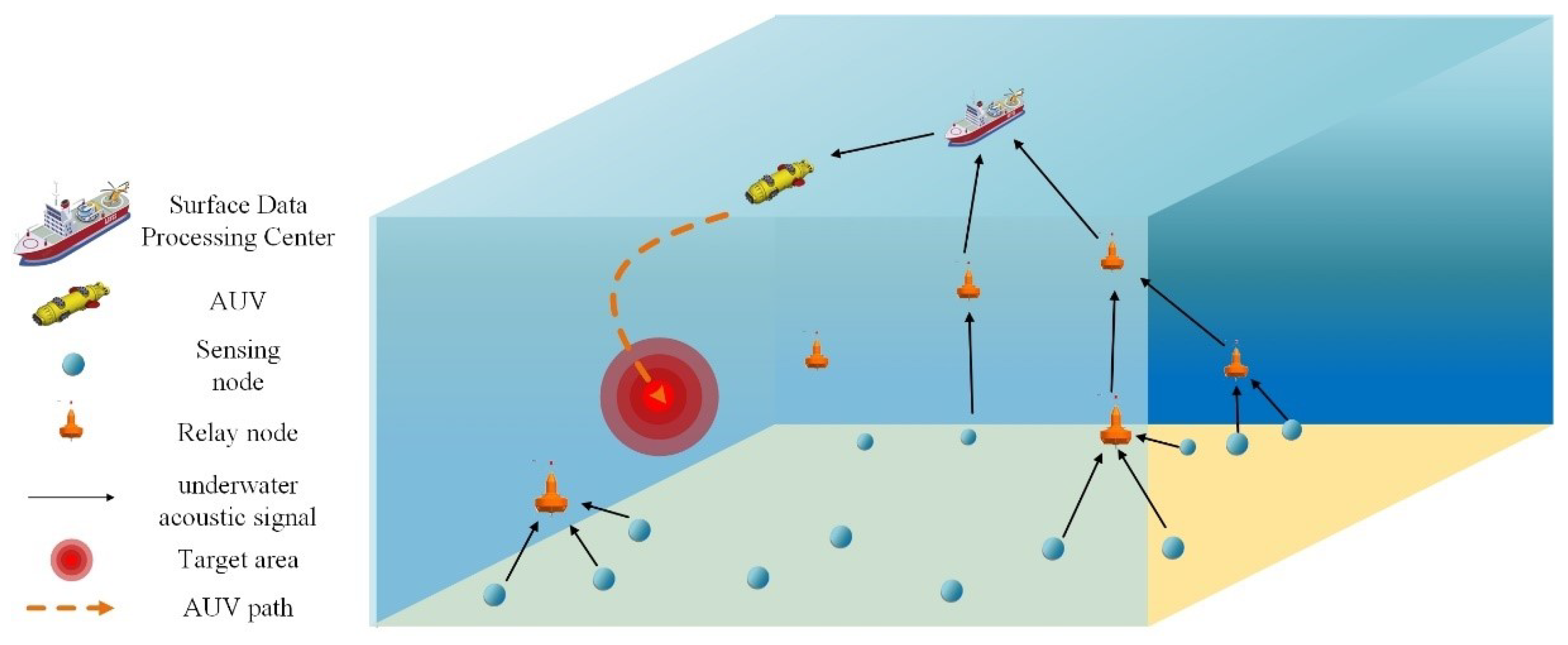
Figure 1 shows an example scenario of AUV-assisted data collection in the IoUT. Sensor nodes are randomly deployed and are responsible for sensing and monitoring environmental data and transmitting the data to the surface destination, i.e., the surface data processing center, via a multi-hop approach. Among them, the nodes responsible for forwarding consume more energy and create routing voids. Some of the nodes may also be detached from the original network due to factors such as ocean currents. In this case, the data collection is assisted by an AUV moving to the target area, e.g., routing voids.
The contributions of this paper are presented as follows:
  • In mobile data acquisition, three types of interference are taken into account, e.g., send interference, receive interference, and send/receive interference. In addition, the data conflicts between adjacent nodes and the link interference between nodes and an AUV are analyzed. Based on this, an Interference Cancellation Graph is established.
  • A MAC Protocol based on an Interference Cancellation Graph (ICG-MAC) is proposed for the AUV-assisted IoUT. It ensures that AUVs can join the network for data transmission immediately after arriving at the target area and do not interfere with the normal work of other sensor nodes.
The remainder of this paper is organized as follows. The next section introduces the related work; Section 3 describes the system model, including the network model and channel model; Section 4 describes the detail of the proposed ICG-MAC; Section 5 presents simulations to analyze the performance of the ICG-MAC; and the conclusion follows in Section 6.

2. Related Works

In the AUV-assisted IoUT, an AUV traverses the network and moves to the sensor nodes for the data collection. Therefore, the MAC protocols are divided into two main categories: AUV-centered MAC protocols and node-centered MAC protocols. The former mainly considers allocating time slots for AUVs to ensure data collection efficiency, while the latter mainly focuses on scheduling time slots for common nodes to reduce data conflicts.

2.1. AUV-Centered MAC Protocols

In the AUV-based data collection MAC protocol, the path planning of AUVs is studied first. The AUV should be moved as close to the nodes as possible to reduce the energy consumption. Also, the overall length of the path is considered to avoid a long data collection delay. In [17], a sensor network for underwater pipeline monitoring is proposed, which uses an AUV to collect the monitoring data along the pipeline and sets different velocity modes for the AUV; however, it is not suitable for networks with a complex topology because of the designed single linear distribution of the sensor nodes. To accommodate more complex networks, in [18], four types of AUV paths are planned according to different application objectives, e.g., SCAN paths, the shortest paths, the lowest energy cluster first paths, and on-the-way lowest energy cluster first paths. In [19], a probabilistic neighborhood is defined based on the information quality of the data, on the basis of which a path is planned for an AUV that maximizes the collected information while minimizing the travel time and energy consumption. The performance of the proposed algorithm is also evaluated by combining two MAC protocols, namely the CSMA and TDMA, respectively. In [20], an energy utilization factor is proposed to save energy and extend the network lifetime by maximizing this factor for network clustering. In [21], a dynamic time-slot allocation MAC protocol for data collection is proposed where the AUV predicts its future location based on its own velocity and chooses a long enough time slot to ensure that it is not disconnected due to movement when communicating with adjacent nodes.

2.2. Node-Centered MAC Protocols

In node-centered MAC protocols, an AUV joining the network for data transmission without interfering with the communication of other nodes is the focus of the study. In [22], a sequence-scheduled and query-based MAC protocol is proposed, which avoids data conflicts by means of the centralized scheduling of buoy nodes and prioritizes the interrogation of AUVs to ensure that their data are transmitted first. In [23], a conflict-free MAC protocol is proposed for regional underwater observation networks, which also uses centralized allocation to avoid conflicts. Considering the uneven network traffic load, in [24], contention-based and reservation-based MAC protocols are designed for low and high traffic load networks, respectively.

2.3. Comparison

In the above study of the MAC protocol, the time-slot allocation of an AUV and the sensing nodes are always considered separately. In fact, when the AUV moves to the sensor nodes for data collection, it changes the original topology of the network and cannot avoid causing interference to the original data communication. Hence, in this study, the time-slot allocation of the AUV and sensor nodes is considered comprehensively to design a conflict-free MAC protocol applicable to dynamic data collection in the IoUT. The comparison between the ICG-MAC and existing related works is presented in Table 1. In a word, the ICG-MAC is a distributed conflict-free MAC protocol with good scalability, and its energy consumption and delay are also acceptable.

3. System Model

This section describes the system model of the proposed ICG-MAC, including the network model, the channel model, and assumptions.

3.1. Network Model and Assumptions

In this study, the IoUT is modeled as a three-dimensional network. Nodes in the network are randomly deployed, and it is assumed that the network is fully connected at initialization. The data collected by nodes in the network are hop-by-hop transmitted to the water surface data processing center, which is also named the sink node. As illustrated in Figure 2, the blue nodes are normal working nodes, which are connected normally and have enough energy. Their data can be transmitted to the sink. The red nodes are low-energy nodes, which work normally but may face death due to insufficient energy. The black nodes are disconnected nodes or isolated nodes. These nodes are disconnected from the network due to the drift of ocean currents or the impact of fish or other marine organisms. Hence, this study designs the MAC protocol of AUV-assisted data transmission, considering low-energy nodes or isolated nodes, and AUV is responsible for data collection to alleviate network congestion and improve network throughput.

3.2. Channel Model

The network performance of underwater acoustic communication is significantly influenced by the communication frequency f k and the distance between communication nodes d, and the signal attenuation is calculated by Equation (1) as follows:
A ( d , f k ) = d e a ( f k ) d
where e = 1.5 , a ( f k ) is calculated by Equation (2):
10 log a ( f k ) = 0.11 f k 2 1 + f k 2 + 44 f k 2 4100 + f k 2 + 2.75 ( 10 4 f k 2 ) + 0.003
For the transmission distance d and carrier frequency f c , the channel response is calculated by Equation (3):
H d , f c = 1 A d , f c
Consequently, at a distance of d and a transmit power of P t , the received signal power is calculated by Equation (4):
P t | H d , f c | 2

4. A MAC Protocol Based on Interference Cancellation Graph

This section presents the details of the proposed ICG-MAC. In the process of data transmission, the target areas that require AUV traversal for data collection are first identified. Then, conflict-free time slots are assigned to nodes in the target region based on Interference Cancellation Graph. Finally, the AUV moves to the target region for data collection. Hence, in this section, the ICG-MAC is presented, including four parts: (1) network initialization, (2) time-slot allocation, (3) target area determination, and (4) conflict-free data collection.

4.1. Network Initialization

During the initialization phase, network layering is first performed. Nodes in different layers of the network can multiplex time slots for data transmission. Then, in each layer, the LEADER node is selected, and the LEADER node is responsible for the distributed and conflict-free time-slot allocation of neighboring nodes.

4.1.1. Network Layering

Inspired by the idea of network layering, the AUV-assisted MAC protocol is designed. As illustrated in Figure 3, nodes in two adjacent layers use different time frames, and layers more than two layers apart can use the same time frames for conflict-free data transmission [13]. In this study, the network is first layered by depth and then time slots are assigned for the nodes. The layer number is calculated by Equation (5) as follows:
S l a y = ( S d e p t h W ) mod F n
where W is the height of a layer, S d e p t h is the depth of the node, and F n is the number of divided time frames, which is usually taken as 3 when W is the maximum communication radius of the node.

4.1.2. Leader Node Selection

During the initialization phase, each node exchanges information with its neighboring nodes by broadcasting its own node ID in the control channel. This process continues for some time to ensure that each node can obtain information about its neighbor nodes. Meanwhile, during the data transmission phase, nodes can obtain the neighbor information by parsing the data header. In order to design the conflict-free MAC protocol, this study first sets the node priority. In the time-slot allocation process, time slots are allocated for the nodes with high priority first. The node priority is set by Equation (6) as follows:
P = f ( d , E r e s ¯ , S l a y ) = d × ( E r e s ¯ + 1 S l a y )
where d is the node degree, E r e s ¯ is the normalized residual energy, and S l a y is the layer number of the node.
The network has been layered above, and the next discussion focuses on the time-slot allocation algorithm for the sensor nodes located in the same layer. The first step is to elect the leader node in the same layer. The role of the leader node is to broadcast the time-slot scheduling information, so the leader node should cover as many nodes as possible. The nodes closer to the middle region in the same layer can cover a larger area and have a higher chance of covering more nodes. As shown in Figure 4, a layer in the network is marked as a rectangular region of W W . A cylindrical region with bottom radius r t h is divided in the center of this rectangular area. r t h is set as W / 4 in this study, and the nodes located in the cylindrical region are the candidate nodes for leader. The node with the largest p-value among all candidate nodes is selected as the leader and is responsible for the time-slot scheduling of the neighboring nodes.

4.2. Time-Slot Allocation

Subject to the limitations of the communication range, nodes that are too far away can use the same time slot or frequency for data transmission without causing interference. Therefore, in order to improve the multiplexing rate of time slots, this study layers the network to ensure that nodes in the layer with a long distance can use the same time slot for communication. Then, different priority levels are assigned to nodes, in order to prioritize time slots for the nodes with more neighbor nodes, more data, and less residual energy to help them transmit data successfully. Finally, in the same layers, nodes are allocated conflict-free time slots based on the analysis of interference models and the creation of Interference Cancellation Graphs. Hence, in this sub-section, the analysis of interference models and the creation of Interference Cancellation Graph are presented, respectively.

4.2.1. Interference Model

In order to design conflict-free MAC, an Interference Cancellation Graph is investigated. In this study, three types of interference are taken into account, e.g., send interference, receive interference, and send/receive interference. As illustrated in Figure 5a, node A and node C cannot send different messages to node B at the same time, which is send interference. As illustrated in Figure 5b, node B cannot send different messages to node A and node C at the same time, which is receive interference. As illustrated in Figure 5c, in half-duplex condition, node B cannot send information to node C while receiving information from node A. This is send/receive interference.

4.2.2. Interference Cancellation Graph

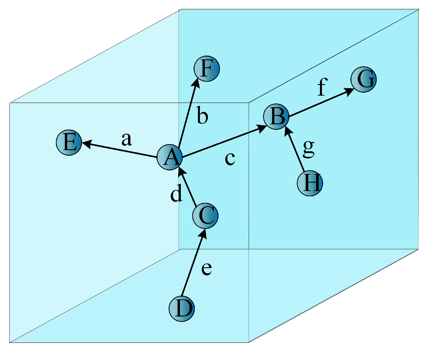
Based on the interference model, the interference graph is established. Assume that Figure 6 shows an actual distribution scenario of nodes, where upper case letters denote nodes and lower case letters denote communication links.
In the traditional construction of a directionless interference graph, adjacent links, or links with common adjacent links are considered to interfere with each other. For example, link c is adjacent to links a and f. It generates receive interference at endpoint B of link c. The interference graph is obtained as shown in Figure 7a. However, in the scenario discussed in this study, data are transmitted from bottom to top, and nodes on the same layer do not transmit downward or parallel, and information is only sent from endpoint B to endpoint G. Therefore, interference between link a and link f is eliminated. The interference graph after optimization is shown in Figure 7b.
On the basis of the interference graph derived above, the vertex set V is obtained. First, the vertex with the largest p-value is selected and assigned a time slot for it in priority. Then, the vertices with no interference are added to the set S. All the vertices that have been assigned time slots are removed from the vertex set V. The above process is repeated until the vertex set V is empty. As shown in Figure 8, suppose the p-values of vertices are 6 , 6 , 7 , 6 , 3 , 5 , 4 , the time-slot allocation process of this graph is as follows. The vertex with the largest p-value is C, and the vertex not connected to it is E. Therefore, there is no interference between C and E, and they can share the same time slot. Remove vertices C and E from the set of vertices V and add them to the set S. When the p-values of vertices are the same, a node can be randomly selected for time-slot allocation. For example, node D is selected. There is no interference between nodes G, F, and D; however, because node F has a higher priority, nodes D and F are first allocated with the same time slot. Then, continue to allocate time slot for nodes B and G. Finally, node A is left with a single time slot.

4.3. Target Area Determination

Network connectivity is very important for real-time data transmission [25]. To ensure that the network can transmit data efficiently and stably, it is essential to determine that the nodes in the network are connected to each other. In [26], a relay location selection algorithm (RLSA) is proposed that can ensure network connectivity with a minimum number of forwarding nodes. In [27], the effect of ocean waves is considered to ensure the connectivity of the network by adding redundant nodes. In [28], a cluster head selection scheme is proposed. The nodes select appropriate cluster heads based on the neighbor density. The cluster heads collect the data of the member nodes in the cluster and then transmit it to the buoy nodes, finding a balance between ensuring network connectivity and saving energy. In [29], the influence of the number of nodes and transmission range on network connectivity was explored. In the above research, network connectivity is ensured by node placement in the network initialization phase or by clustering. In the above study, network connectivity was ensured by arranging node locations during the initialization phase or by using a clustering approach. These methods are not applicable in networks with dynamically changing network topology. Hence, in this study, the connectivity and robustness of the network are greatly improved by introducing AUV-assisted sensor nodes for data transmission.
The underwater environment is complex and volatile, and the network topology changes over time. Nodes may be disconnected from the network due to drifting currents or the influence of marine life such as fish, or the original network topology may be affected by energy depletion and death. Hence, in this study, firstly, the important nodes that change the network topology need to be identified. Secondly, the AUV moves to the network area where these nodes are located to assist in data collection, and then the MAC protocol is designed for time-slot allocation.
A network can be modeled as a graph, denoted by G = { V , E } , where the nodes in the network are the vertices of the graph, denoted by V, and the communication links that exist between the nodes are the edges of the vertices, denoted by 
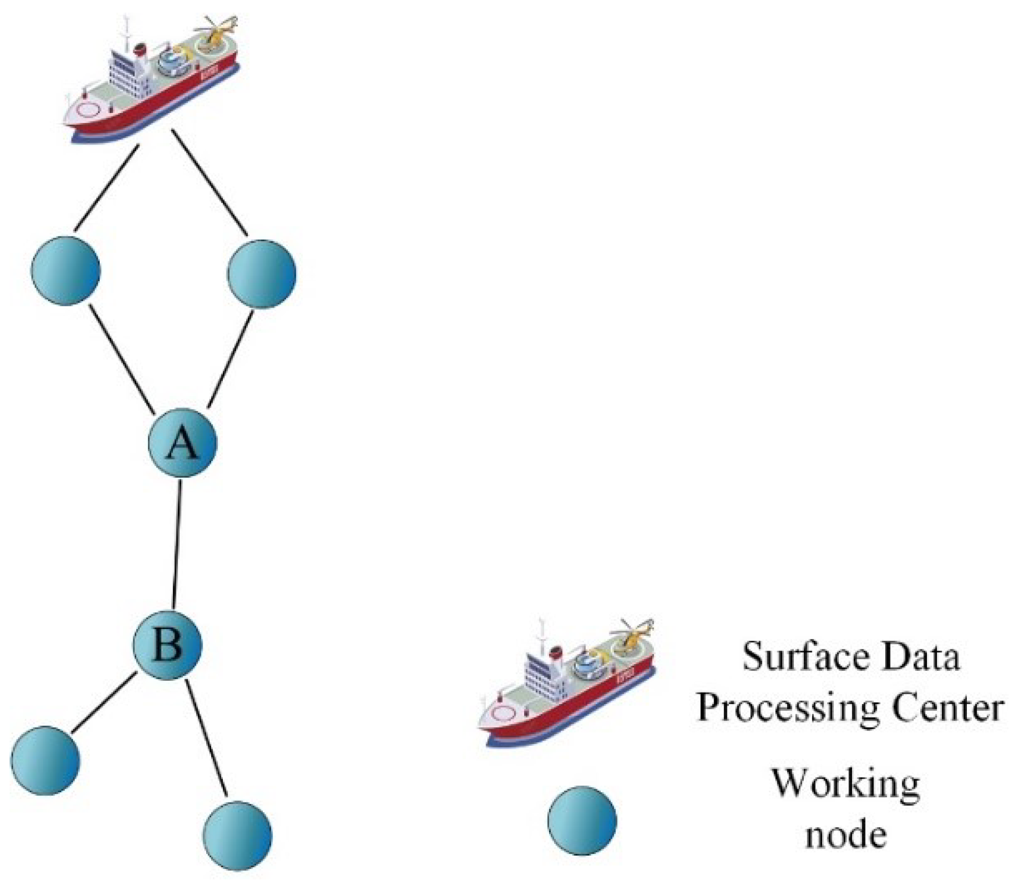
E. If after eliminating a point in the graph and the edges connected to it, it appears that two points cannot be connected in the graph, and the removed point is named the cut vertex of the graph. As illustrated in Figure 9, node A and B are cut vertexes. If the cut vertexes are disconnected, the data cannot be transmitted. Hence, this study uses AUV to connect the area where the cut vertexes are located for data collection.
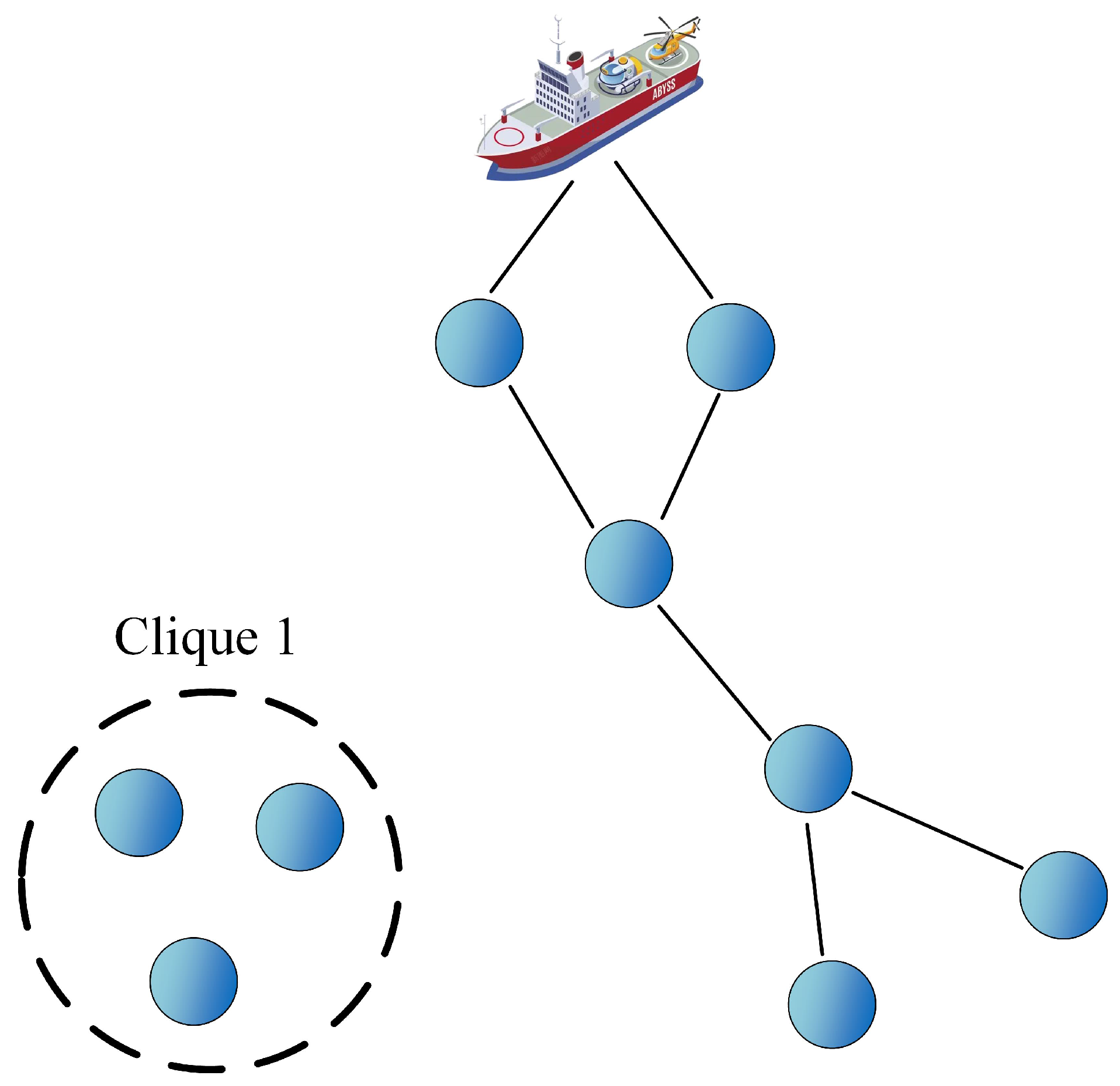
If the cut vertex is an isolated node, then the AUV can go directly to the location of the node for data collection. If the cut vertex causes several nodes to be unconnected, a clique of vertexes disengage from the original network, as shown in Figure 10. As the AUV moves to the cut clique, many vertexes need to upload data, so a conflict-free time-slot allocation mechanism is required for these nodes. In this study, all the isolated vertexes or cut cliques form the target region. The target region search needs to be performed first, and the AUV moves to the target region for data collection. In order to find the target area, the “importance” value of each node in the target area is defined by Equation (7) as follows:
I = d ( 1 E r e s E i n i t )
where d is the degree of the vertex, i.e., the number of neighbors of the node, E r e s is the residual energy of the node, and E i n i t is the initial energy of the node. I is proportional to d because the higher the number of neighboring nodes, the heavier the amount of data forwarding, and therefore the more important the node is. The residual energy and the “importance” value are inversely related because the lower the energy, the higher the risk of the node dying, so the AUV is urgently needed to share the data transmission task.
For a cut clique, its “importance” value is calculated by Equation (8):
I ¯ = 1 n i = 1 n I ( i )
where n is the number of vertexes in the cut clique, and I ( i ) is the “importance” value of the i-th vertex. AUV traverses target areas for data collection based on the order of “importance” values, from largest to smallest.

4.4. Conflict-Free Data Collection

When the AUV reaches the target area, it needs to join the original network for data transmission, then how to join the network with minimum conflict cost is the focus of study in this section.
The number of edges of an undirected complete graph with n vertices is n ( n 1 ) 2 . When a new node is added to the network, then the number of edges increases by n ( n + 1 ) 2 n ( n 1 ) 2 = n . That is, the least desirable case is that communication links exist between the newly added node and the previous n nodes, at which point the newly added node requires n time slots. Therefore, to enable an AUV to join the network without affecting the original communication of the network without conflict, sufficient communication time slots need to be reserved for the AUV.
In this study, each time slot that has been allocated is further divided into two sub-time slots. When the AUV performs data collection, a notification packet is broadcast through the control channel. All nodes that receive the notification packet and have data packets to be transmitted concede one of the sub-time slots to communicate with the AUV and keep one of the sub-time slots to maintain the original data communication in the network. As shown in Figure 11, the green squares indicate the packets sent by node 1, the red squares indicate the packets sent by node 2, and the small yellow squares indicate the control packets of AUV. Before the AUV is reached, two sub-time slots are used for data transmission between nodes 1 and 2. After the AUV arrives, the notification packet is broadcast first for data set. Both nodes 1 and 2 yield the time slot denoted by a to deliver packets to the AUV and reserve the time slot denoted by b for data transmission with neighboring nodes.

5. Simulation and Analysis

The performance of the algorithm is analyzed in relation to four aspects: network connectivity, network throughput, energy consumption, and network lifetime. First, the network connectivity is compared with and without AUV participation, respectively; second, the Slotted-ALOHA [7] and IG-TDMAMAC [14] are selected as the comparison protocols, and the performance of the algorithms in terms of the energy consumption and network throughput is analyzed. The Aqua-Sim [30] is chosen for the performance evaluation. The simulator’s built-in channel model, energy model, random noise model, Random Waypoint mobility model, and traffic generation protocol are used for the simulation. In the standard channel model, a single channel is used for the data transmission. Based on the energy model, nodes communicate omnidirectionally rather than directionally, i.e., all neighbors within the communication range of the node have the opportunity to receive data. In addition, Aqua-SIM has been supplemented with the ICG-MAC protocol’s code written in C++ and the simulation result data are analyzed using MATLAB. In the simulation scenario, the AUV is initialized at the location of the surface control center and moves at a speed of 5 m/s. A total of 32 sensor nodes are randomly deployed in a range of 2000 m × 2000 m × 2000 m. The communication radius of the nodes is 500 m. The packet size is set to 1024 bits and the control packet size is 20 bits. Figure 12, Figure 13, Figure 14, Figure 15 and Figure 16 present the results of an average of 30 simulations. In addition, the simulation parameters are shown in Table 2.

5.1. Comparison of Network Connectivity

In this study, the network connectivity is defined as Equation (9):
C = d t o t a l N
where d t o t a l is the sum of the degrees of the connected nodes and N is the number of nodes in the network.
As illustrated in Figure 12, the connectivity of the networks with and without the presence of AUVs are compared. It can be observed that at the beginning, the connectivity of the networks with and without an AUV presence is similar. Over time, the connectivity of the network without an AUV gradually decreases, while the connectivity of the network with AUV assistance remains relatively smooth. This is because in the network without AUV assistance, due to factors such as ocean currents, the nodes may drift and disconnect, or die early due to excessive energy consumption, and the whole network shows regional disconnections, leading to a decrease in connectivity, whereas in the protocol proposed in this paper, the buoy calculates the location of the disconnected locations or the set of locations of nodes with too low energy and assigns the AUV to the target area for data collection, thus always maintaining high network connectivity.

5.2. Comparison of Network Throughput

In this study, the network throughput is defined as the amount of data transferred over a period of time, which is calculated by Equation (10):
T = N r e c × L t
where N r e c is the number of packets received, L is the packet size, and t is the time spent for the entire data collection process.
As shown in Figure 13, the ICG-MAC protocol proposed in this paper has the best performance among the three protocols, followed by the IG-TDMA MAC and the Slotted-ALOHA MAC protocol. This is due to the fact that both the proposed ICG-MAC and the IG-TDMAMAC are contention-free MAC protocols. There is no conflict between the nodes and therefore no need for retransmission, so it is more efficient. As the simulation proceeds, more and more nodes sense the data and participate in the data transmission, so the throughput increases accordingly. However, when too many nodes die, the network becomes too sparse, so the throughput gradually decreases. In addition, the proposed ICG-MAC protocol outperforms the IG-TDMAMAC protocol because the auxiliary data collection by an AUV is considered in this paper. The Slotted-ALOHAMAC protocol, on the other hand, is a contention-based protocol, which is prone to encountering hidden terminal problems during channel competition, resulting in data conflicts and packet loss, and thus has the worst performance among the three protocols. In addition, the network traffic with and without AUV assistance are compared. As shown in Figure 14, the traffic grows over time and the network with the presence of AUVs consistently outperforms the network without the presence of AUVs.

5.3. Comparison of Energy Consumption

As shown in Figure 15, the IG-TDMA MAC protocol consumes the most energy among the three protocols, followed by the ICG-MAC protocol proposed in this paper, and the Slotted-ALOHAMAC protocol consumes the least energy. This is because under the competition mechanism of the Slotted-ALOHA, some nodes fail to obtain the channel usage and do not transmit data, so the network energy consumption is lower in the same time. The ICG-MAC protocol and IG-TDMAMAC protocol give the nodes sufficient opportunities to transmit, so higher energy is consumed, sacrificing some energy in exchange for the increased throughput.

5.4. Comparison of Network Lifetime

As shown in Figure 16, the network lifetime is compared. The life cycle of all three protocols grows as the number of nodes grows. Among the three protocols, the Slotted-ALOHA has the longest network lifetime, followed by the ICG-MAC proposed in this paper, and the IG-TDMAMAC protocol has the shortest network lifetime. This is due to the fact that the ICG-MAC and IG-TDMAMAC have more service traffic and therefore consume more energy in the same time, resulting in a shorter network life cycle compared to the Slotted-ALOHAMAC protocol. However, because the proposed protocol in this paper introduces an AUV to balance the energy consumption in the network and alleviate the route void problem, its network life cycle is longer than that of the IG-TDMAMAC protocol.

6. Conclusions

For the problems of unstable data transmission and energy limitation in the IoUT, this paper proposes an AUV-assisted MAC protocol, named ICG-MAC, which effectively improves the network connectivity and network throughput and alleviates the hot-zone problem. The protocol is mainly divided into three parts. First, the surface data processing center calculates the location of the nodes that need AUV-assisted data transmission nodes, i.e., the target area, based on the location of the nodes and residual energy. Then, based on the link interference model, an interference-free map is established and time slots are allocated for the nodes in the target area. Finally, when the AUV arrives at the designated area, it takes up part of the data transmission work without affecting the nodes in the network that are operating normally, relieving the network congestion and improving the network throughput.
In future work, the cooperative data transmission problem among multiple AUVs will be further investigated. First, the issue of path planning for multiple AUVs should be investigated. In this paper, we study the target area search and assume that AUVs can arrive in a straight line as soon as possible, while in practical applications, the movement of AUVs is affected by environmental factors such as obstacles, thus reducing the efficiency of the data collection. Second, a more intelligent allocation algorithm that combines the factors of energy, location, and communication resources to assign tasks to different AUVs in a more reasonable and efficient way is required. Last but not least, the safety issue in data collection has been neglected. Nodes are generally considered to be reliable and trustworthy. However, in practice, the network is vulnerable to malicious attacks due to its openness and unattended nature. It is important to identify the reliability of nodes and motivate them to actively participate in collaborative data forwarding.

Author Contributions

Conceptualization, J.J. and W.T.; methodology, J.J. and W.T.; validation, G.H. and W.T.; formal analysis, J.J. and G.H.; investigation, W.T.; writing—original draft preparation, J.J. and W.T.; writing—review and editing, J.J., G.H. and W.T.; visualization, W.T.; supervision, G.H. All authors have read and agreed to the published version of the manuscript.

Funding

This research was funded in part by “the National Natural Science Foundation of China under Grant No. 62072155, U22A2011, and Grant 62072072”, “the Natural Science Foundation of Jiangsu Province under Grant BK20221230”, “the Six talent peaks project in Jiangsu Province, No.XYDXX-012”.

Institutional Review Board Statement

Not applicable.

Informed Consent Statement

Not applicable.

Data Availability Statement

Not applicable.

Conflicts of Interest

The authors declare no conflict of interest.

References

  1. Oceanix. Available online: https://oceanix.com/ (accessed on 1 January 2023).
  2. Tao, S.; Liu, H.; Wang, S.; Li, C. Construction of Smart Coastal Cities Based on Digital Government. J. Coast. Res. 2020, 110, 154–158. [Google Scholar] [CrossRef]
  3. Saira, B.A.; Kalpna, G. Smart City in Underwater Wireless Sensor Networks. In Energy-Efficient Underwater Wireless Communications and Networking; IGI Global: Hershey, PA, USA, 2021; pp. 287–301. [Google Scholar]
  4. Domingo, M.C. An overview of the internet of underwater things. J. Netw. Comput. Appl. 2012, 35, 1879–1890. [Google Scholar] [CrossRef]
  5. Kumar, A.; Sharma, S. Demur and Routing Protocols with application in Underwater Wireless Sensor Networks for Smart City. In Energy-Efficient Underwater Wireless Communications and Networking; IGI Global: Hershey, PA, USA, 2020. [Google Scholar]
  6. Vieira, L.F.M.; Kong, J.; Lee, U.; Gerla, M. Analysis of Aloha Protocols for Underwater Acoustic Sensor Networks. ACM WUWNET’06—Poster. 2006. Available online: http://mslab.kaist.ac.kr/wikipages/files/luiz_aloha.pdf (accessed on 8 March 2023).
  7. Roberts, L.G. ALOHA packet system with and without slots and capture. ACM SIGCOMM Comput. Commun. Rev. 1975, 5, 28–42. [Google Scholar] [CrossRef]
  8. Xu, M.; Liu, L. Sender-Receiver Role-Based Energy-Aware Scheduling for Internet of Underwater Things. IEEE Trans. Emerg. Top. Comput. 2016, 7, 324–336. [Google Scholar] [CrossRef]
  9. Hayajneh, M.; Khalil, I.; Gadallah, Y. An OFDMA-Based MAC Protocol for Under Water Acoustic Wireless Sensor Networks. In Proceedings of the 2009 International Conference on Wireless Communications and Mobile Computing: Connecting the World Wirelessly, IWCMC’09, Leipzig, Germany, 21–24 June 2009; Volume 6, pp. 810–814. [Google Scholar]
  10. Khalil, I.M.; Gadallah, Y.; Hayajneh, M.; Khreishah, A. An Adaptive OFDMA-Based MAC Protocol for Underwater Acoustic Wireless Sensor Networks. Sensors 2012, 12, 8782–8805. [Google Scholar] [CrossRef] [PubMed] [Green Version]
  11. Kim, J.P.; Lee, J.W.; Jang, Y.S.; Son, K.; Cho, H.S. A CDMA-Based MAC Protocol in Tree-Topology for Underwater Acoustic Sensor Networks. In Proceedings of the International Conference on Advanced Information Networking, Bradford, UK, 26–29 May 2009. [Google Scholar]
  12. Fan, G.; Chen, H.; Xie, L.; Wang, K. An Improved CDMA-Based MAC Protocol for Underwater Acoustic Wireless Sensor Networks. In Proceedings of the 2011 7th International Conference on Wireless Communications, Networking and Mobile Computing, Wuhan, China, 23–25 September 2011. [Google Scholar]
  13. Alfouzan, F.A.; Shahrabi, A.; Ghoreyshi, S.M.; Boutaleb, T. An Energy-conserving Collision-free MAC Protocol for Underwater Sensor Networks. IEEE Access 2019, 7, 27155–27171. [Google Scholar] [CrossRef]
  14. Zhang, R.; Cheng, X.; Cheng, X.; Yang, L. Interference-Free Graph Based TDMA Protocol for Underwater Acoustic Sensor Networks. IEEE Trans. Veh. Technol. 2017, 67, 4008–4019. [Google Scholar] [CrossRef]
  15. Júnior, E.P.M.C.; Vieira, L.F.M.; Vieira, M.A.M. UW-SEEDEX: A pseudorandom-based MAC protocol for underwater acoustic networks. IEEE Trans. Mob. Comput. 2021, 21, 3402–3413. [Google Scholar] [CrossRef]
  16. Zeng, H.; Hou, Y.T.; Shi, Y.; Lou, W.; Kompella, S. A Distributed Scheduling Algorithm for Underwater Acoustic Networks with Large Propagation Delays. IEEE Trans. Commun. 2017, 65, 1131–1145. [Google Scholar] [CrossRef]
  17. Jawhar, I.; Mohamed, N.; Al-Jaroodi, J.; Zhang, S. An Architecture for Using Autonomous Underwater Vehicles in Wireless Sensor Networks for Underwater Pipeline Monitoring. IEEE Trans. Ind. Inform. 2019, 15, 1329–1340. [Google Scholar] [CrossRef]
  18. Khan, M.; Ahmed, S.H.; Jembre, Y.Z.; Kim, D. An energy-efficient data collection protocol with AUV path planning in the Internet of Underwater Things. J. Netw. Comput. Appl. 2019, 135, 20–31. [Google Scholar] [CrossRef]
  19. Hollinger, G.A.; Choudhary, S.; Qarabaqi, P.; Murphy, C.; Mitra, U.; Sukhatme, G.S.; Stojanovic, M.; Singh, H.; Hover, F. Underwater data collection using robotic sensor networks. IEEE J. Sel. Areas Commun. 2012, 30, 899–911. [Google Scholar] [CrossRef] [Green Version]
  20. Zhuo, X.; Liu, M.; Wei, Y.; Yu, G.; Qu, F.; Sun, R. AUV-Aided Energy-Efficient Data Collection in Underwater Acoustic Sensor Networks. IEEE Internet Things J. 2020, 7, 10010–10022. [Google Scholar] [CrossRef]
  21. Zhou, J.; Wang, X.; Zhang, B. Dynamic Timeslot MAC Protocol for AUV Underwater Communication. In Proceedings of the 2020 39th Chinese Control Conference (CCC), Shenyang, China, 27–29 July 2020. [Google Scholar]
  22. Huang, J.; Chi, C.; Wang, W.; Huang, H. A Sequence-Scheduled and Query-Based MAC Protocol for Underwater Acoustic Networks with a Mobile Node. J. Commun. Inf. Netw. 2020, 5, 150–159. [Google Scholar] [CrossRef]
  23. Gang, Q.; Kuang, B.; Zhang, J.; Wang, C. Conflict-free MAC protocol for regional underwater observation networks. In Proceedings of the National Doctoral Academic Forum on Information and Communications Technology 2013, Beijing, China, 21–23 August 2013. [Google Scholar]
  24. Min, D.; Chen, H.; Lei, X. A hybrid MAC protocol in data-collection-oriented underwater acoustic sensor networks. In Proceedings of the OCEANS 2017—Aberdeen, Aberdeen, UK, 19–22 June 2017. [Google Scholar]
  25. Wu, C.; Chen, H.; Liu, J. A survey of connectivity restoration in wireless sensor networks. In Proceedings of the 2013 3rd International Conference on Consumer Electronics, Communications and Networks, Xianning, China, 20–22 November 2013. [Google Scholar]
  26. Ma, C.; Liang, W.; Zheng, M.; Sharif, H. A Connectivity-Aware Approximation Algorithm for Relay Node Placement in Wireless Sensor Networks. IEEE Sens. J. 2016, 16, 515–528. [Google Scholar] [CrossRef]
  27. Yapicioglu, T.; Oktug, S. Effect of wave height to connectivity and coverage in sea surface wireless sensor networks. In Proceedings of the 2009 24th International Symposium on Computer and Information Sciences, Guzelyurt, Northern Cyprus, 14–16 September 2009. [Google Scholar]
  28. Lee, S.H.; Lee, S.; Song, H.; Lee, H.S. Gradual cluster head election for high network connectivity in large-scale sensor networks. In Proceedings of the 13th International Conference on Advanced Communication Technology (ICACT2011), Gangwon, Republic of Korea, 13–16 February 2011. [Google Scholar]
  29. Dagdeviren, O.; Akram, V.K. The Effect of Random Node Distribution and Transmission Ranges on Connectivity Robustness in Wireless Sensor Networks. In Proceedings of the 2019 International Symposium on Networks, Computers and Communications (ISNCC), Istanbul, Turkey, 18–20 June 2019. [Google Scholar]
  30. Aqua-Sim-NG Simulatior. August 2017. Available online: https://github.com/rmartin5/aqua-sim-ng (accessed on 5 December 2019).
Figure 1. An example of AUV-assisted data collection in IoUT.
Sustainability 15 04876 g001
Figure 2. The network model of ICG-MAC.
Sustainability 15 04876 g002
Figure 3. An example of network layering.
Sustainability 15 04876 g003
Figure 4. The selection of leader nodes.
Sustainability 15 04876 g004
Figure 5. Three types of interference. (a) Send interference. (b) Receive interference. (c) Send/receive interference.
Sustainability 15 04876 g005
Figure 6. An example of a node distribution scenario.
Sustainability 15 04876 g006
Figure 7. Directionless interference graph. (a) Original interference graph. (b) Simplified interference graph.
Sustainability 15 04876 g007
Figure 8. Interference Cancellation Graph.
Sustainability 15 04876 g008
Figure 9. An example of cut vertexes.
Sustainability 15 04876 g009
Figure 10. An example of a cut clique.
Sustainability 15 04876 g010
Figure 11. Sub-time-slot division and data transmission.
Sustainability 15 04876 g011
Figure 12. Comparison of network connectivity.
Sustainability 15 04876 g012
Figure 13. Comparison of network throughput.
Sustainability 15 04876 g013
Figure 14. Comparison of network traffic.
Sustainability 15 04876 g014
Figure 15. Comparison of energy consumption.
Sustainability 15 04876 g015
Figure 16. Comparison of network lifetime.
Sustainability 15 04876 g016
Table 1. Comparison between ICG-MAC and existing related works.
AlgorithmEnergy ConsumptionTransmission DelayData ConflictDistributedChannel UtilizationScalability
ALOHAHighHighHighYesLowFair
Slotted-ALOHAHighHighHighYesLowFair
CSMA/CAHighHighLowYesLowFair
Adaptive OFDMAFairLowLowYesHighFair
IG-TDMAFairFairNoNoHighLow
ICG-MACFairFairNoYesHighHigh
Table 2. The simulation parameters.
ParametersValues
The velocity of AUV5 m/s
Packet size1024 bit
Packet transmission rate10 kbps
Communication radius500 m
Network size2000 m × 2000 m × 2000 m
Control package size20 bit
Transmitting power2 W
The number of nodes32
Disclaimer/Publisher’s Note: The statements, opinions and data contained in all publications are solely those of the individual author(s) and contributor(s) and not of MDPI and/or the editor(s). MDPI and/or the editor(s) disclaim responsibility for any injury to people or property resulting from any ideas, methods, instructions or products referred to in the content.

