Article

Deformation State Analysis and Design Method of Bottom-Confined Gravity Retaining Walls

Institute of Exploration Technology, Chinese Academy of Geological Sciences, Chengdu 611734, China
*
Authors to whom correspondence should be addressed.
Sustainability 2023, 15(5), 4405; https://doi.org/10.3390/su15054405
Submission received: 2 January 2023 / Revised: 27 February 2023 / Accepted: 28 February 2023 / Published: 1 March 2023
(This article belongs to the Section Hazards and Sustainability)

Abstract

:
The deformation failure modes of gravity retaining walls include overturning, toppling, deep sliding, and eccentric failure. The complex eccentric failure mode, which involves the multi-stage deformation of retaining walls, suffers from a lack of mechanical models and design theories. Based on the basic theory of reinforced concrete construction, this study established a deformation calculation model of bottom-confined reinforced concrete gravity retaining walls (RC-GRWs), which are composed of tensile, compressive, and rigid zones. Then, this study defined RC-GRWs’ normal-operation, cracking, yield, and ultimate limit states, as well as the displacement of RC-GRWs in these states, according to the concrete cracking and steel reinforcement yield conditions. Accordingly, this study proposed a design method and process to determine the deformation of bottom-confined RC-GRWs. A project case shows that the calculation method for RC-GRW deformation proposed in this study can effectively assess the deformation state of in-service retaining walls and that optimized cracked retaining walls can meet the deformation-based design requirements.

1. Introduction

Gravity retaining walls refer to walls made of stone masonry or concrete that rely on their own weight to resist the lateral soil pressure. These walls are effective in controlling small- and medium-sized slopes or landslides and are divided into mortar rubble, plain concrete, and reinforced concrete types according to their material composition. Since reinforced concrete retaining walls can withstand greater soil pressure and landslide thrust than the other two types of walls, they are more widely used [1,2].
The deformation failure modes of gravity retaining walls include overturning, toppling, deep sliding, and eccentric failure (Figure 1) [3,4]. There are corresponding design methods of gravity retaining walls for different failure modes. For the overturning failure mode, a retaining wall is generally assumed to be a rigid body, and its design and calculation can be achieved by verifying the overturning stability of its heel [5]. For the toppling and sliding failure modes of a retaining wall, it is feasible to determine the toppling stability of the bottom of the retaining wall [6] and then conduct the design and calculation of the wall by enhancing the friction at the wall’s bottom. Insufficient burial depth of retaining walls may cause the deep sliding of slopes or landslides. Generally, it is necessary to verify the stability of the slopes or landslides in the case of deep sliding [7,8] in order to design the geometry of retaining walls to meet the overall stability requirements. However, for the eccentric failure mode of retaining walls, the mechanical model has not yet been established and there is a lack of corresponding design and calculation methods.
Focusing on the eccentric failure mode of concrete gravity retaining walls, this study established a deformation calculation model of bottom-confined RC-GRWs based on the basic theory of reinforced concrete construction and defined the normal-operation, cracking, yield, ultimate limit states of RC-GRWs, as well as the displacement of RC-GRWs in these states. Based on these, this study proposed the design method and process for the deformation of bottom-confined RC-GRWs. Finally, this study assessed the deformation state of an in-service retaining wall using this method and conducted the optimal design for the deformed retaining wall.

2. Calculation Model and Deformation States

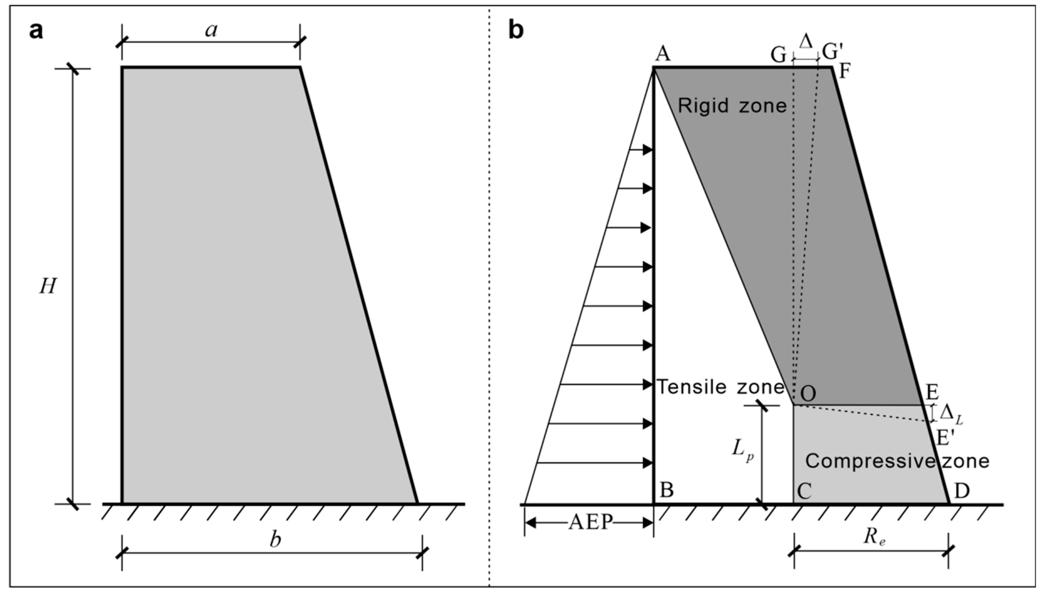
2.1. Model and Assumptions

RC-GRWs are reinforced concrete assemblies. When a reinforced concrete wall is subjected to horizontal load and strong bottom confinement, tensile and compressive stress zones will form inside the wall [9,10,11]. Generally, for a reinforced concrete wall, the tensile strain is concentrated within its 1/2 height of the wall, while the compressive strain primarily occurs within the range of 1.5 times the height of the compressive zone. Moreover, the tensile and compressive strains are distributed in a trapezoidal pattern on the base of the wall, with the concentration zone of the tensile strain much higher than that of the compressive strain [12]. By studying the deformation properties of reinforced concrete walls [13], Takahashi et al. found that the strain within the top 1/3 height of a reinforced concrete wall on the tensile and compressive sides is 8.7 and 6.1 times that within the bottom 1/3 height of the wall, respectively. This finding indicates that the top of a reinforced concrete wall has a higher deformation amplitude than its bottom.
Figure 2a shows an RC-GRW in the shape of a right trapezoid, whose altitude, top base width, and bottom base width are denoted by H, a, and b. This RC-GRW can be simplified as the model shown in Figure 2b for the deformation calculation based on the above analyses. A gravity retaining wall has a fixed bottom and is subjected to the active earth pressure (AEP) in the horizontal direction, and it is assumed that pressure is distributed within a triangular in a gravity retaining wall. The deformation calculation model of a retaining wall consists of a tensile zone, a compressive zone, and a rigid zone [11,12]. As shown in Figure 2b, O is the center of rotation, G is the projection of O on the top of the wall, Re is the equivalent radius of rotation, and Lp is the height of the equivalent plastic hinge zone.
To calculate the deformation amplitude of a retaining wall, the following assumptions were made according to the calculation model shown in Figure 2b:
(1)
The interfaces of the tensile, compressive, and rigid zones of the model satisfied the deformation compatibility condition;
(2)
Under the action of horizontal load and the dead load of the retaining wall, the rigid body of the retaining wall rotated around O, and the horizontal displacement of G was defined as the displacement of the top of the retaining wall (i.e., |GG′| = Δ), and the compressive strain was distributed vertically and evenly in the plastic hinge zone;
(3)
The equivalent radius of rotation Re was a parameter related to the height of the compressive zone x in the retaining wall section, the average height of the retaining wall section hw, and the length of the confined boundary members Lc. In other words, Re = Re (x, hw, Lc);
(4)
The height of the equivalent plastic hinge zone Lp was a parameter related to the axial compression ratio n and the aspect ratio of the retaining wall H/hw, i.e., Lp = Lp (n, H/hw).

2.2. Deformation States

In this study, the cracking state of RC-GRWs was defined as the state in which the concrete in the plastic hinge zone shows the presence of sliding-caused microfractures and enters the stage of the stable development of fractures; the yield state was defined as the state in which the concrete in the plastic hinge zone exhibits visible fractures and enters the stage of the unstable development of fractures; and the ultimate limit state was defined as the state in which the concrete in the plastic hinge zone reaches its ultimate compressive strain [14]. Studies [15,16] show that the stress and strain of concrete are approximately 30–50% and 10–30% of its peak stress and strain, respectively, when concrete starts to enter the cracking state and are approximately 75–90% and 50–70% of its peak stress and strain, respectively, when concrete starts to enter the yield state. Yan et al. [14] suggested that the cracking displacement and the yield displacement of a retaining wall assembly should be defined as the displacement of the top of the retaining wall when the strain of the concrete in the plastic hinge zone reaches 25% and 70% of its peak strain, respectively, and the ultimate displacement of a retaining wall assembly should be defined as the displacement of the top of the retaining wall when the compressive strain of the concrete in the plastic hinge zone reaches its ultimate strain.

3. Deformation Calculation of a Retaining Wall

3.1. Constitutive Model of Reinforced Concrete

The whole stress–strain curve equation of concrete proposed in reference [17] was employed as the constitutive model of confined concrete in this study (Figure 3):
{ y = α a x + ( 3 2 α a ) x 2 + ( α a 2 ) x 3 , x 1 y = x Ψ α d ( x 1 ) n + x , x > 1
where x = ε/εcc and ε is the strain; y = σ/σcc, where σ is the stress; σcc [18] and εcc are the peak stress and peak strain of reinforced concrete, respectively, when confinement is considered; αa is the parameter of the stress–strain ascending segment, αa = 2.4 − 0.0125σcc; n = 1 + exp(−3ω) [19], where ω is the lateral confinement coefficient of concrete and can be calculated using the following equations [17]:
ω = 0.1659 ( k 1 ) 1.434
k = 1 + sin φ 1 sin φ
where φ is the internal friction angle of concrete.
The effective confinement coefficient of concrete confined by hoop reinforcement is Ψ = 0.021/ρv [17], where ρv is the volumetric ratio of hoop reinforcements and is calculated using the following equation:
ρ v = n i A s v i l i A c o r s
where ni is the number of hoop reinforcements; Asvi is the cross-sectional area of a single hoop reinforcement; li is the length of a hoop reinforcement; Acor is the cross-sectional area of the concrete core within the range of internal surface area of reinforcement mesh or spiral indirect reinforcements, and s is the spacing of the reinforcement mesh or spiral indirect reinforcements.
Parameter αd of the stress–strain descending segment of confined concrete is calculated using the following equation [20,21]:
α d = 3 d 17 ( d 1 ) n
where
d = 0.0033 ε c c [ 1 + 2.18 × 10 5 ( 2 ω f c ε c c / f y ) 1.2 ]
where fc is the uniaxial compressive strength of concrete and fy is the yield strength of reinforcements.
As shown in Figure 2b, under the action of axial compression load, the lateral deformation of concrete in the compressive zone is confined by both hoop reinforcements and concrete in the tensile zone. As a result, concrete in the compressive zone is in the biaxial compression state. Both the peak stress and the peak strain when a concrete assembly fails are greater under the biaxial compression than those under the uniaxial compression. When confinement is considered, the peak stress and peak strain of concrete confined by hoop reinforcements are calculated using the following equation [16,22]:
{ σ c c = ( 1 + 0.5 λ v ) f c c F F C M 3 ε c c = ( 1 + 2.5 λ v ) ( 3 σ c c f c 2 ) ε p
where fcc is the peak stress of concrete confined by hoop reinforcements; F and FCM are the calculated area and the compressive area, respectively; εp is the peak strain of concrete, which is 2.0 × 10⁻³ for plain concrete under the uniaxial compression; λv is the characteristic value of hoop reinforcements, which is calculated using the following equation:
λ v = ρ v f y h / f c
where fyh is the design value of the tensile strength of indirect reinforcements.
For a confined retaining wall assembly, its ultimate strain can be calculated using the basic relationship of confined concrete stated in reference [23]:
ε c c u = ( 2.34 + 2.49 λ v 0.73 ) ε c c
where εccu is the ultimate strain of confined concrete, and the physical meanings of other parameters are as stated above.

3.2. Geometric Relationship

As shown in Figure 2b, assuming that the compressive strain value of concrete is ε, the vertical compressive deformation amplitude ΔL of the compressive edge of the plastic hinge zone can be obtained as follows according to assumption (2):
Δ L = ε L p
According to the geometric relationship shown in Figure 2b:
Δ Δ L = | O G | R e
where Δ is the displacement of the top of the retaining wall assembly, and ΔL is the vertical deformation amplitude of the compressive edge of the plastic hinge zone.
The lateral displacement angle θ for the top of the retaining wall is:
θ = Δ / H
The compressive strain ε of the compressive zone in the bottom section of a retaining wall is composed of the strain caused by both the bending moment and the dead load of the retaining wall. The axial force Nm in the compressive zone caused by the bending moment is calculated as follows. According to the equivalence principle of force, the bending moment of a point is equivalent to the product of the force creating the moment and the arm of the force. It is assumed that Nm passes through the centroid positions of the compressive and tensile zones and that the neutral axis passes through the centroid of the bottom section. For a trapezoidal section, the arm of force has a length of b ( 2 a b ) 3 ( a + b ) according to the geometric relationship. In this case, the axial force Nm caused by the bending moment can be obtained as follows:
N m = 3 M ( a + b ) b ( 2 a + b )
where M is the bending moment at the wall bottom.
Load is evenly distributed when the retaining wall is subjected to the dead load N and can be obtained according to the areas of the compressive and tensile zones. The pressure of the concrete in the compressive zone Nn is:
N n = N b ( a b + R e ) b ( 2 a b + R e ) a R e
where N is the dead load of the retaining wall.
The compressive strain of both the axial force Nm caused by the bending moment and the pressure Nn caused by the dead load is:
ε = N m + N n R e L p E r c
where Erc is the elastic modulus of reinforced concrete.
As shown by the comparison between retaining wall assemblies with the same height-to-width ratio and the same length of the confined portion, a shorter compressive zone is associated with a higher rotation capacity and greater displacement of the top of the retaining wall assemblies. In other words, there is a negative correlation between the height of the compressive zone and the displacement of the top. Reference [14] suggested that the equivalent radius of rotation be determined according to the following equation:
R e = ζ 1 L c + ζ 2 ( h w x )
where ζ1 and ζ2 are coefficients related to materials and are 0.5 and 0.1, respectively, for concrete with a strength grade equal to or less than C50; hw is the average height of a retaining wall assembly; x and Lc are the height of the actual compressive zone and the length of the confined boundary members of the retaining wall assembly, respectively.
Reference [24] suggested that the height of the equivalent plastic hinge zone Lp be calculated as follows:
L p = 0.2 h w + 0.044 H
In the process of the on-site assessment of the deformation state of a retaining wall, substituting the measured horizontal displacement of the retaining wall into Equation (10) yields the compressive strain of the retaining wall. The cracking, yield, or ultimate limit state of the retaining wall under on-site conditions is determined according to the definitions of deformation states in Section 2.2. Similarly, substituting the angle of rotation of the retaining wall measured on-site into Equations (10) and (11) yields the deformation amplitude of the retaining wall. When the deformation state and the angle of rotation of the retaining wall are difficult to measure, the compressive strain ε can be calculated using Equations (13)–(17) based on the bending moment and dead load of the retaining wall. Then, the present deformation state of the retaining wall can be determined.

4. Design Method Based on Deformation States

4.1. Equations for the Ultimate Limit State of the Bearing Capacity of a Retaining Wall

When a retaining wall assembly is subjected to the horizontal pressure of soil and the dead load of the wall, the tensile and compressive zones at the bottom first enter the yield state. Figure 4a shows a cross-section of the compressive zone, which has a width of c = 1, a length of ai, and a height of hi from the wall bottom (Figure 4b). Figure 4c,d show the strain and stress of the section when it reaches its ultimate limit state of bearing capacity. The following equation can be obtained according to the equilibrium conditions of force and moment of force in the section:
{ N d = A s p σ s p + N c A s c σ s c N s w M d = A s p σ s p ( a i 2 a s c ) + M c M s w N d ( a i / 2 a s p )
where Nd and Md are the design values of the pressure and bending moment of the retaining wall section, respectively; σsp and σsc are the stress of the compressive and tensile longitudinal reinforcements at the end of the retaining wall, respectively, and their design values are the cracking stresses of the compressive and tensile longitudinal reinforcements, respectively; Asp and Asc are the sectional areas of longitudinal compression and tension reinforcements at the end of the retaining wall, respectively; Nc is the pressure the concrete in the compressive zone bears; Mc is the bending moment at position As created by the concrete pressure in the compressive zone; Nsw is the resultant force of the distribution reinforcements; Msw is the bending moment at position As of Nsw; asp and asc are thicknesses of the covers of compressive and tensile longitudinal reinforcements, respectively; the physical meanings of other parameters are as stated above.
Nsw is calculated as follows. In the case of large eccentric compression, the distribution reinforcements in the compressive zone yield. In this case, the stress of distribution reinforcements near the neutral axis is small and is not considered. In contrast, only the bearing capacity of the tensile distribution reinforcements within the range of the effective height (ai − asp) minus 1.5 times the height of the compressive zone is considered [14], and it is assumed that the bearing capacity does not exceed the cracking stress. Msw is taken as zero in the case of small eccentric compression and is calculated as follows in the case of large eccentric compression:
{ N s w = ( a i a s p 1.5 x ) f y w ρ w M s w = 0.5 ( a i a s p 1.5 x ) 2 f y w ρ w
where fyw and ρw are the strength design value and reinforcement ratio of distribution reinforcements, respectively, and are taken as zero in the case of small eccentric compression.
Nc and Mc can be obtained as follows according to the assumption about plane cross-section and the concrete constitutive model adopted in this study:
  • when x < ai,
    { N c = 0.2 f c x M c = 0.25 f c x [ 0.8 ( a i a s p ) 0.33 x ]
  • when xai,
    { N c = 0.25 f c a i M c = 0.25 f c a i ( a i / 2 a s p )

4.2. Design Process

A reinforced concrete retaining wall was designed in the following steps (Figure 5):
  • The design parameters of the retaining wall, including its height, bottom width, top width, and burial depth, were preliminarily calculated based on information such as the geometry of the slope or landslide, the position of the sliding surface, and the soil pressure (residual sliding force). Then, the concrete grade and the models of the longitudinal, distribution, and hoop reinforcements were selected for the retaining wall, and the reinforcement spacing was determined.
  • Following GB 50330-2019 Technical Code for Building Slope Engineering, the anti-overturning and -sliding performances, deep sliding, and the strength of the retaining wall with the preliminarily proposed dimensions were verified. If the performances and the strength were qualified, the deformation state of the retaining wall was further verified. Otherwise, the parameters of the retaining wall such as the geometry and strength were rechecked and redetermined.
  • The volumetric ratio and the characteristic value of hoop reinforcements were calculated based on the preliminarily proposed reinforcement conditions for the retaining wall assembly. The vertical load N and the bending moment M that the retaining wall bears were calculated based on the horizontal pressure of the soil and the dead load of the retaining wall. Then, the height of the compressive zone in the calculated retaining wall section was determined using Equations (18)–(21). The equivalent radius of rotation and the length of the equivalent plastic hinge zone were calculated using Equations (16) and (17). They were substituted into Equation (15), yielding the compressive strain, which was then compared with the cracking strain.
  • When the calculated compressive strain met the condition of ε < 25% εcc and the retaining wall had the proper size, concrete grade, and reinforcements, it was unnecessary to correct the proposed parameters of the retaining wall. Otherwise, corrections were required.

5. Case Verification

5.1. Analysis of the Deformation State of an In-Service Retaining Wall

5.1.1. Overview of the Retaining Wall Project

A certain high-speed passenger line (DK126 + 125–DK126 + 345) has a length of 220 m on the left side. This passenger line was completed through excavation, with bedding developing on its right side, where strata have an attitude of N35°E/50°SE. A railroad-cut gravity retaining wall made of cast-in-place reinforced concrete has been designed for this line. As shown in Figure 6, three rock (soil) layers lie behind the retaining wall, i.e., silty clays and strongly and weakly weathered silty to fine-grained sandstones from the top of the railroad cut to the bottom. These layers have a thickness of 2 m, 3 m, and 10–20 m, respectively, and their physical and mechanical parameters are shown in Table 1. The constitutive relationship between the soil and rock masses conforms to the Mohr–Coulomb criterion.
The retaining wall has a height of 5 m, a bottom width of 2 m, a top width of 0.8 m, and a burial depth of 1.0 m. The foundation of the retaining wall is located in the weakly weathered silty to fine-grained sandstones and has an allowable bearing capacity of 350 kPa. Behind the wall is a platform with a width of 2 m, and above the platform is a slope with a height of 10 m and a gradient of 1:1.25.
Regarding the strength, the retaining wall has an internal friction angle of φ = 45°, a unit weight of γ = 24 kN/m3, a bottom friction coefficient of f = 0.5, and a tensile strength of σt = 500 kPa.

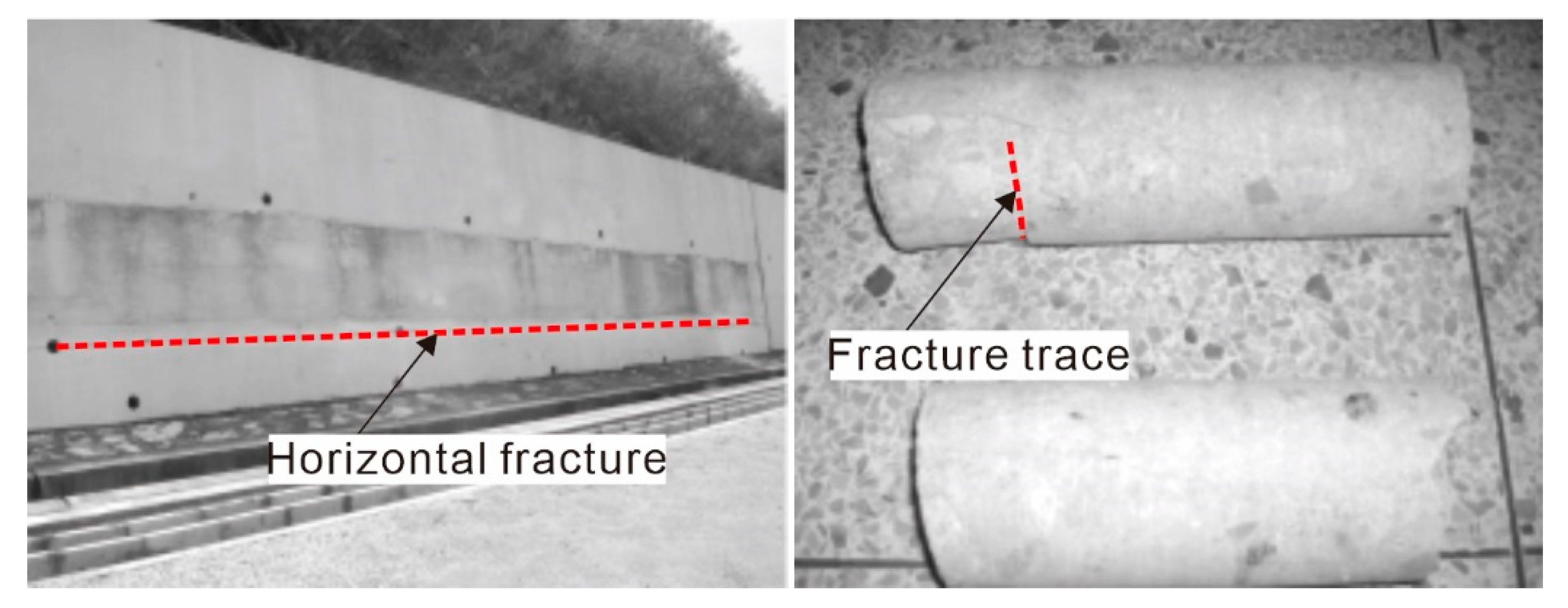
5.1.2. Deformation of the Retaining Wall

The retaining wall was completed on 30 July 2009 and cracked approximately 10 days later. According to the field investigation, the retaining wall has horizontal penetrating fractures along the strike of the retaining wall, with a maximum width of 1 mm and a depth of 5 cm, as shown in Figure 7. The cores show that there are no significant fractures and only fracture traces exist in the deep part. Accordingly, water intrusion and shear failure hardly occur, as shown in Figure 7.
The retaining wall is mainly located in the area with strongly to weakly weathered silty to fine-grained sandstones and without unfavorable geological conditions such as faults and fractured zones. Moreover, groundwater is not well-developed and strata have strong self-stability in this area, without toppling and deep sliding, and the retaining wall does not show significant overturning deformation. Therefore, it can be concluded that the rear of the retaining wall is subjected to high rock and soil pressure and that the retaining wall is strongly confined at the foundation. As a result, the retaining wall has not deformed greatly to offset the rock and soil pressure at the rear. Instead, the high strain has occurred in the retaining wall, further leading to the horizontal cracking of the retaining wall.

5.1.3. Analysis of the Deformation State of the Retaining Wall

As verified during the design of the retaining wall, the anti-overturning and -sliding performances, deep sliding, and strength all meet the stability requirements. Given this, this study only verified the deformation performance of the retaining wall. As shown in Figure 4c, the retaining wall is subjected to the maximum compressive strain at the bottom. Therefore, this study selected the bottom section of the wall to calculate the compressive strain and analyze the deformation state of the wall. The HRB335 reinforced steel bars with a diameter of 10 mm are used as the hoop reinforcements of the retaining wall. The hoop reinforcement mesh has a spacing of 40 cm. The hoop reinforcements deployed along the sliding direction of the slope have a length of 2 m and a spacing of 30 cm, and those deployed perpendicular to the sliding direction of the slope have a length of 1 m and a spacing of 25 cm. Thus, the volumetric ratio of hoop reinforcements ρv of the retaining wall is:
ρ v = 0.01 2 × 3.14 ( 8 × 1 + 2 × 2 ) 2 × 1 × 0.4 = 0.0055
The design tensile strength of indirect reinforcements is fyh = 300 MPa and the uniaxial compressive strength of concrete is fc = 45 MPa. Therefore, the characteristic value λv of the hoop reinforcements is:
λ v = 0.0055 × 300 / 45 = 0.0367
The concrete confined by hoop reinforcements has a peak stress of fcc = 60 MPa, a calculated area of F = 7 m2, and a compressive area of FCM = 1.75 m2, and εp is taken as 2.0 × 10⁻³. Then, the peak stress σcc of concrete confined by hoop reinforcements when confinement is considered is:
σ c c = ( 1 + 0.5 × 0.0367 ) × 60 × 10 3 × 7 1.75 3 = 97.0 MPa
The peak strain εcc of concrete confined by hoop reinforcements when confinement is taken into account is:
ε c c = ( 1 + 2.5 × 0.0367 ) × ( 3 × 97 45 2 ) × 0.002 = 0.00975
Under the horizontal pressure of soil, the bending moment at the bottom of the retaining wall was calculated to be M = 3196.14 kN·m/m based on the theory of active earth pressure. Then, the axial force Nm caused by the bending moment is:
N m = 3 × 3196.14 × ( 0.8 + 2 ) 2 × ( 2 × 0.8 + 2 ) = 3728.83 kN / m
The actual compressive zone of the retaining wall assembly has a height of x = 0.05 m, the confined boundary members have a length of Lc = 0, ζ1 and ζ2 are taken as 0.5 and 0.1, and the retaining wall assembly has an average height of hw = (0.8 + 2)/2 = 1.4 m. Then, the equivalent radius of rotation Re is:
R e = 0.5 × 0 + 0.1 × ( 1.4 0.05 ) = 0.135   m
The retaining wall has a dead weight of N = 182 kN/m, so the pressure on the concrete in the compressive zone Nn is:
N n = 182 × 2 × ( 0.8 2 + 0.135 ) 2 × ( 2 × 0.8 2 + 0.135 ) 0.8 × 0.135 = 607.62   kN / m
The height of the equivalent plastic hinge zone Lp is:
L p = 0.2 × 1.4 + 0.044 × 5 = 0.5   m
The reinforced concrete has an elastic modulus of Erc = 2 × 10⁴ MPa, so the total compressive strain ε of the axial force Nm caused by the bending moment and the pressure Nn caused by the dead load is:
ε = 3728.83 + 607.62 0.135 × 0.5 × 2 × 10 7 = 0.00321 > 25 % ε c c = 0.00244
and
ε = 0.00321 < 70 % ε c c = 0.00683
According to the definitions of strains caused by the cracking and yielding of a retaining wall, the retaining wall is in the cracking state and does not yield. This conclusion is consistent with the observation that horizontal fractures do not completely penetrate inside the retaining wall.

5.2. Optimal Design of the Retaining Wall Based on Cracking State

As mentioned above, checking revealed that the anti-overturning and -sliding performances, deep sliding, and strength of the retaining wall all meet the stability requirements, while the strength checking considered the control effects of the longitudinal and distribution reinforcements on the strength of the retaining wall. Equation (7) shows that the deformation of a concrete assembly is inseparable from the confinement by hoop reinforcements. Therefore, this study only designed hoop reinforcements rather than optimizing the size, longitudinal reinforcements, and distribution reinforcements of the retaining wall.
The original hoop reinforcement scheme for the retaining wall is as follows: HRB335 reinforced steel bars with a diameter of 10 mm are used as hoop reinforcements; the hoop reinforcement mesh has a spacing of 40 cm; the hoop reinforcements deployed along the sliding direction of the slope have a length of 2 m and spacing of 30 cm; the hoop reinforcements deployed perpendicular to the sliding direction of the slope have a length of 1 m and spacing of 25 cm.
The optimized hoop reinforcement scheme for the retaining wall is as follows: HRB335 reinforced steel bars with a diameter of 12 mm are used as hoop reinforcements; the hoop reinforcement mesh has a spacing of 30 cm; the hoop reinforcements deployed along the sliding direction of the slope have a length of 2 m and spacing of 18 cm; the hoop reinforcements deployed perpendicular to the sliding direction of the slope have a length of 1 m and spacing of 18 cm.
The compressive strain ε of the retaining wall after the optimization of the hoop reinforcements is:
ε = 0.00362 < 25 % ε c c = 0.00244
The retaining wall is in the cracking state, meeting the deformation-based design requirements. The compressive and flexural capacities of the retaining wall were checked as follows:
HRB335 reinforced steel bars with a diameter of 28 mm and spacing of 30 cm are adopted in the compressive and tensile zones of the retaining wall. The sectional areas of the compressive and tensile longitudinal reinforcements at the end of the retaining wall Asp and Asc are:
A s p = A s c = 3 × 0.28 2 × 3.14 = 0.00739   m 2
With the cracking strain as the design state of the retaining wall, the optimized peak stress is σ c c = 116.7   MPa , so the stresses of the compressive and tensile longitudinal reinforcements σsp and σsc at the end of the retaining wall section are:
σ s p = 0.25 × 116.7 = 291.76   MPa σ s c = 1.95 0.05 × 0.25 × 291.76 = 284.46   MPa
The pressure Nc and the bending moment Mc of the concrete in the compressive zone are:
N c = 0.2 × 45 × 10 3 × 0.5 = 4500   kN / m M c = 0.25 × 45 × 10 3 × 0.05 × [ 0.8 × ( 2 0.05 ) 0.33 × 0.05 ] = 7846.88   kN m / m
The resultant force Nsw and the bending moment Msw of the distribution reinforcement are:
N s w = 0.25 × ( 2 0.05 1.5 × 0.05 ) × 300 × 10 3 × 0.02 = 90   kN / m
M s w = 0.5 × ( 2 0.05 1.5 × 0.05 ) 2 × 300 × 10 3 × 0.02 = 13.5   kN m / m
The design values of the pressure Nd and bending moment Md that the retaining wall section bear are:
N d = 0.00739 × 10 3 × ( 291.76 284.46 ) + 4500 90 = 2523.67   kN / m > N = 182   kN / m
M d = 0.00739 × 291.76 × 10 3 × ( 2 2 × 0.05 ) + 7846.88 13.5 2523.67 × ( 2 / 2 0.05 ) = 5845.49   kN / m > M = 3196.14   kN m / m
As shown by the calculation results, both the compressive and the anti-bending design values of the retaining wall after the optimization of hoop reinforcements are greater than the originally designed bearing capacities, thus meeting the deformation-based design requirements.

6. Conclusions

This study established a deformation calculation model of bottom-confined RC-GRWs, which is composed of tensile, compressive, and rigid zones, and defined the normal-operation, cracking, yield, and ultimate limit states of the walls, as well as the displacement of the walls in these states. Based on these, this study proposed the deformation calculation method for bottom-confined RC-GRWs. Moreover, it developed the design method and process of bottom-confined RC-GRWs based on the cracking state. The project case indicates that the deformation calculation method for bottom-confined RC-GRWs proposed in this study can effectively assess the deformation state of in-service retaining walls and that the optimized cracked retaining walls can meet the deformation-based design requirements.

Author Contributions

Methodology, Y.Z.; Validation, Y.Z. and J.L.; Investigation, Q.C.; Writing—original draft, Y.Z.; Writing—review and editing, S.S. All authors have read and agreed to the published version of the manuscript.

Funding

This work was funded by Ministry of Science and Technology of the People’s Republic of China (grant number 2019YFC1509904) and China Geological Survey (grant number DD20231745).

Institutional Review Board Statement

Not applicable.

Informed Consent Statement

Not applicable.

Data Availability Statement

The data presented in this study are available on request from the corresponding author.

Conflicts of Interest

The authors declare that they have no known competing financial interests or personal relationships that could influence the work reported in this paper.

References

  1. Ahn, I.S.; Cheng, L. Seismic analysis of semi-gravity RC cantilever retaining wall with TDA backfill. Front. Struct. Civ. Eng. 2017, 11, 455–469. [Google Scholar] [CrossRef]
  2. Gabr, M.; Rasdorf, W.; Findley, D.; Butler, C.; Bert, S. Comparison of Three Retaining Wall Condition Assessment Rating Systems. J. Infrastruct. Syst. 2018, 24, 04017037. [Google Scholar] [CrossRef]
  3. Sadoglu, E. Design optimization for symmetrical gravity retaining walls. Acta Geotech. Slov. 2014, 11, 70–79. [Google Scholar]
  4. Ahmed, M.S.; Munwar, B.B. External stability analysis of narrow backfilled gravity retaining walls. Geotech. Geol. Eng. 2021, 39, 1603–1620. [Google Scholar] [CrossRef]
  5. Zhang, C.G.; Chen, X.D.; Zhu, D.H. Anti-overturning design and parametric analysis for rigid retaining wall of foundation pit in unsaturated soils. J. Cent. South Univ. (Sci. Technol.) 2016, 47, 569–576. [Google Scholar] [CrossRef]
  6. Xu, P.; Hatami, K. Sliding stability and lateral displacement analysis of reinforced soil retaining walls. Geotext. Geomembr. 2019, 47, 483–492. [Google Scholar] [CrossRef]
  7. Bishop, A.W. The use of slip circle in stability analysis of slopes. Géotechnique 1955, 5, 7–17. [Google Scholar] [CrossRef]
  8. Morgenstern, N.R.; Price, V.E. The analysis of the stability of general slip surfaces. Geotechnique 1965, 15, 79–93. [Google Scholar] [CrossRef]
  9. Ni, X.Y.; Cao, S.Y.; Li, Y.Z.; Jing, D.H. Shear strength prediction of reinforced concrete walls. Struct. Design Tall Spec. 2019, 28, e1599. [Google Scholar] [CrossRef]
  10. Shegay, A.; Motter, C.; Elwood, K.; Henry, R. Deformation Capacity Limits for Reinforced Concrete Walls. Earthq. Spectra 2019, 35, 1189–1212. [Google Scholar] [CrossRef]
  11. Takazawa, H.; Hirosaka, K.; Miyazaki, K.; Tohyama, N.; Saigo, S.; Matsumoto, N. Numerical Simulation of Impact Loading for Reinforced Concrete Wall. Int. J. Pres. Ves. Pip. 2018, 167, 66–71. [Google Scholar] [CrossRef]
  12. Escolano, M.D.; Klenke, A.; Pujol, S.; Benavent-Climent, A. Failure Mechanism of Reinforced Concrete Structural Walls with and without Confinement. In Proceedings of the 15th World Conference on Earthquake Engineering, Lisbon, Portugal, 24–28 September 2012. [Google Scholar]
  13. Takahashi, Y.K.; Ichinose, T.; Sanada, Y.; Matsumoto, K.; Fukuyama, H.; Suwada, H. Flexural drift capacity of reinforced concrete wall with limited confinement. Aci Struct. J. 2013, 110, 95–104. [Google Scholar] [CrossRef]
  14. Yan, L.Z.; Liang, X.W.; Xu, J.; Wang, H. Research on calculation method of deformation capacity of reinforced concrete shear wall. Eng. Mech. 2014, 31, 92–98. [Google Scholar] [CrossRef]
  15. Gao, D.Y.; Liu, J.X. The Basic Theory of Rigid Fiber Concrete; Science and Technology Literature Press: Beijing, China, 1994; pp. 310–336. (In Chinese) [Google Scholar]
  16. Cai, S.H. Concrete and reinforced concrete local bearing strength. China Civ. Eng. J. 1963, 9, 1–10. [Google Scholar]
  17. Shi, Q.X.; Rong, C.; Zhang, T.; Wang, Q.W. A Practical Stress-Strain Model for Confined Concrete. J. Build. Mater. 2017, 20, 49–54. [Google Scholar] [CrossRef]
  18. Hong, K.; Han, S.H.; Yi, S.T. High-strength concrete columns confined by low-volumetric-ratio lateral ties. Eng. Struc. 2006, 28, 1346–1353. [Google Scholar] [CrossRef]
  19. Cusson, D.; Paultre, P. Stress-strain model for confined high-strength concrete. J. Struct. Eng. 1995, 121, 468–777. [Google Scholar] [CrossRef]
  20. Razvi, S.; Saatcioglu, M. Confinement model for high-strength concrete. J. Struct. Eng. 1999, 125, 281–289. [Google Scholar] [CrossRef]
  21. Scott, B.D.; Park, R.; Priestley, M.J.N. Stress-strain behaviour of concrete confined by overlapping hoops at low and high strain rates. J. Am. Concr. Inst. 1982, 79, 13–27. [Google Scholar] [CrossRef]
  22. Guo, Z.H.; Shi, X.D. Principles and Analysis of Reinforced Concrete; Tsinghua University Press: Beijing, China, 2003. [Google Scholar]
  23. Qian, J.R.; Cheng, L.R.; Zhou, D.L. Axial compression performance of ordinary stirrup confined concrete column. J. Tsinghua Uni. 2002, 42, 1369–1373. [Google Scholar] [CrossRef]
  24. Paulay, T.; Priestley, M.J.N. Seismic Design of Reinforced Concrete and Masonry Buildings; John Wiley & Sons, Inc.: New York, NY, USA, 1992. [Google Scholar]
Figure 1. Deformation failure modes of gravity retaining walls (O is the center of rotation; (a) overturning; (b) toppling; (c) deep sliding; (d) eccentric failure).
Sustainability 15 04405 g001
Figure 2. Geometry and deformation calculation model of a retaining wall ((a) geometry; (b) deformation calculation model).
Sustainability 15 04405 g002
Figure 3. Whole stress–strain curve equation of confined concrete. σ is the stress; ε is the strain; σcc and εcc are the peak stress and peak strain of reinforced concrete, respectively; εccu is the ultimate strain of confined concrete.
Sustainability 15 04405 g003
Figure 4. Ultimate stress states of a retaining wall section. ((a) deformed zones and section location; (b) diagram showing the section; (c) stress distribution on the section; (d) bearing capacity of the section).
Sustainability 15 04405 g004
Figure 5. Design process of a retaining wall based on the deformation state.
Sustainability 15 04405 g005
Figure 6. Section of a retaining wall project.
Sustainability 15 04405 g006
Figure 7. Horizontal fractures and cores of the retaining wall.
Sustainability 15 04405 g007
Table 1. Physico-mechanical parameters of the rock (soil) layers.
Rock (Soil) LayerUnit Weight/kn/m3Cohesion/kpaInternal Friction Angle/°
Silty clays18.510.519.2
Strongly weathered silty to fine-grained sandstones20.312.321.5
Weakly weathered silty to fine-grained sandstones21.070.929.6
Disclaimer/Publisher’s Note: The statements, opinions and data contained in all publications are solely those of the individual author(s) and contributor(s) and not of MDPI and/or the editor(s). MDPI and/or the editor(s) disclaim responsibility for any injury to people or property resulting from any ideas, methods, instructions or products referred to in the content.

