Article

Sustainable High-Speed Milling of Magnesium Alloy AZ91D in Dry and Cryogenic Conditions

by
Nabil Jouini
1,2,*,
Mohd Shahfizal Mohd Ruslan
3,4,
Jaharah A. Ghani
3 and
Che Hassan Che Haron
3
1
Mechanical Engineering Department, College of Engineering, Prince Sattam Bin Abdulaziz University, Alkharj 11942, Saudi Arabia
2
Laboratoire de Mécanique, Matériaux et Procédés (LR99ES05), École Nationale Supérieure d’Ingénieurs de Tunis, Université de Tunis, Tunis 1008, Tunisia
3
Department of Mechanical and Manufacturing Engineering, Faculty of Engineering and Built Environment, Universiti Kebangsaan Malaysia, Bangi 43600, Selangor, Malaysia
4
German-Malaysian Institute, Jalan Ilmiah, Taman Universiti, Kajang 43000, Selangor, Malaysia
*
Author to whom correspondence should be addressed.
Sustainability 2023, 15(4), 3760; https://doi.org/10.3390/su15043760
Submission received: 12 January 2023 / Revised: 15 February 2023 / Accepted: 16 February 2023 / Published: 18 February 2023
(This article belongs to the Special Issue Advances in Sustainable Machining Processes and Technologies)

Abstract

:
Magnesium alloy AZ91D is used extensively in the automotive industry because of its high strength-to-weight ratio. Typically, components produced using the alloy are required to have good surface finish and to contribute to high productivity but require long cutting times. Cryogenic cooling is an environmentally friendly technology which has been proven to improve cutting tool life and surface finish. This paper presents an investigation on the effects of dry and cryogenic cutting conditions at a high cutting speed regime for milling of magnesium alloy. This study focused on a high-speed regime due to the chips of magnesium alloy being highly combustible and an effective means of decreasing the temperature in the cutting zone was of great concern. The machining experiment was carried out using uncoated carbide end milling utilizing a full factorial design (L16) with cutting speeds of 900 m/min and 1300 m/min, feed rate of 0.02 mm/tooth and 0.05 mm/tooth, axial depth of cut at 0.2 mm and 0.3 mm, and radial depth of cut at 10 mm and 40 mm. For dry machining, the longest tool life at flank wear (VBmax) of 0.21 mm was at 30 min, which was obtained at cutting speeds of 1300 m/min, feed rate of 0.02 mm/tooth, axial depth of cut at 0.2 mm, and radial depth of cut at 40 mm. Using this cutting condition, a mirror-like surface of 0.106 µm was produced. For machining under cryogenic condition at VBmax of 0.2 mm, the maximum tool life of 1864 min was achieved at a cutting speed of 900 m/min, feed rate of 0.02 mm/tooth, axial depth of cut of 0.3 mm, and radial depth of cut of 40 mm. Under this cutting condition, a lower surface finish of 0.091 µm was obtained. It can be concluded that the application of liquid nitrogen (LN2) is very effective in enhancing the tool life and in obtaining a better-machined surface, especially at a lower cutting speed of 900 m/min. A longer tool life and high-quality machined parts will significantly improve the productivity and cost savings in the related industry.

1. Introduction

Magnesium alloy is known for its excellent physical and mechanical properties such as low density, very high strength–to-weight ratio, high stiffness, and mechanical castability [1]. Magnesium alloy is preferred to aluminum or steel alloy in the automotive industry due to its high strength-to-weight ratio [2]. Magnesium and aluminum alloys have become key materials in producing lighter and more efficient vehicles in the automotive industry [3]. Magnesium, when compared with aluminum, is lighter and offers a better solution for fuel cells, hybrids, and internal combustion engines. Although its practical applications are limited due to its poor corrosion resistance, its use has recently been more widespread in the automotive industry because of its advantages in addressing energy and environmental concerns. Leading car manufacturers have been searching for a replacement for steel with lighter materials such as magnesium to achieve lightweight construction, without compromising on rigidity. Consequently, this can lead to greenhouse gas reductions and can limit exhaust emissions to satisfy legislative and consumer requirements for safer and cleaner vehicles [4]. Despite growing interest in magnesium alloys, very little data exist on its machinability such as the wear mechanism of the cutting tool and the influence of cutting fluids in the machining process.
According to Ghosh et al. [5], the occurrence of tool wear in the machining process is a significant problem that needs to be addressed. Worn out cutting tools could cause unwanted vibrations, deteriorating the surface finish and quality of the machined parts and introducing dimensional inaccuracies. The machine tool itself could also be further affected. In certain situations, the cutting tool may break during the machining process, resulting in a sudden release of the load and consequential inertial effects, leaving incurable stress effects on the workpiece as well as the machining center. Tool wear effects can be minimized by estimating tool wear with the purpose of optimizing cutting parameters such as cutting speed, feed rate, and depth of cut, or by replacing the worn tool with a pristine one [5]. Shi et al. [6] reported that the dominant wear characteristics of carbide inserts in high-speed machining of magnesium alloy under dry condition were flaking, depth of cut nose wear and abrasion. At cutting speeds of 1600 m/min, extensive flaking was observed as the significant failure mode, while failure at 1800 and 2000 m/min was attributed to serious flank wear and gross fractures, respectively.
Bermingham et al. [7] stated that to improve cutting tool life, other key factors such as effective utilization of a conventional cutting fluid are deemed effective solutions to prevent heat generation and transfer it to the tool, in addition to any heat extraction offered by the coolant at the cutting zone. Liquid nitrogen (LN2) as a coolant during the machining process has recently gained popularity as it is a clean, inexpensive, and non-toxic fluid that has no environmental contamination issues [7]. Wang et al. [8] revealed that high-speed machining under cryogenic conditions obtained higher machining quality and tool service life as compared to conventional methods. Cryogenic conditions can quadruple service life with negligible negative impact of wear to improve surface quality [8]. Kaynak et al. [9] concurred with these findings when machining NiTi shape memory alloys with cryogenic cooling, reporting that the tool wear and notch wear at the depth of cut line had been reduced at high cutting speeds and at relatively low cutting speeds, respectively. Hou et al. [10] stated that machining magnesium alloy at high cutting speeds generates thin and light chips that are prone to ignition due to their low heat capacity and high thermal expansion. A built-up edge may be produced when cutting speeds exceed critical value, thus resulting in serious adverse effects to the surface quality of the component [11]. Presently, little research has been conducted on the effects of cutting parameters and cryogenic cutting conditions toward surface quality when machining magnesium alloy.
Pu et al. [12] investigated the effects of dry and cryogenic machining on the surface integrity of AZ31B magnesium alloy using differing radii of cutting edge tools. The researchers found that utilization of a cryogenic coolant (liquid nitrogen) and large edge radius tool improved surface roughness by about 20% as compared to dry machining. The effect of feed rate is significant to the surface roughness while using rotary tool in the machining of magnesium alloy AZ31 [13]. Chirita and Tampu [14] discovered that cooling conditions and feed per tooth are the most vital factors in achieving a good surface finish. Their study showed that machining under minimum quantity lubrication (MQL) systems allowed for better and more consistent surface roughness values when compared to dry machining. Finer and better surface finishes can also be achieved during machining when smaller feed rate per tooth is used. Similar findings had been reported by Guo et al. [15], where it had been found that dry machining magnesium calcium alloy yielded surface roughness (Ra) values as low as 0.2 µm, with the lowest feed rate of 0.05 mm/rev.
AZ91D alloy is the most common die casting alloy which is used in more than 90% of all magnesium die cast products [3] and commonly used for non-structural and low-temperature components such as brackets, covers, cases, and oil pump housings. To date, no work has been reported which has evaluated tool wear characteristics and surface finishes achieved after high-speed milling of magnesium alloy under dry and cryogenic conditions. As previously explained, cryogenic cooling is effective in enhancing the tool life and in reducing the negative effect of tool wear in machining. Therefore, this study aimed to thoroughly investigate the tool wear mechanism and surface roughness of magnesium alloy under dry and cryogenic high-speed milling conditions using an uncoated carbide cutting tool.

2. Materials and Methods

The dry and cryogenic machining experiments were conducted on a CNC milling machine (SPINNER VC450, SPINNER Machining Centre, Germany), with a maximum spindle speed of 15,000 rpm. The workpiece material used was magnesium alloy AZ91D with dimensions of 150 × 150 × 50 mm. Prior to experimentation, the workpiece was pre-milled to remove the original skin layer which contained hard particles such as oxides and carbides. The chemical composition of AZ91D was as shown in Table 1. The cryogenic condition was achieved by using liquid nitrogen delivered directly to the cutting zone during the machining process via nozzle, as shown in Figure 1. In the experiment, one nozzle at 45 degree was pointed at the flank face with liquid nitrogen under 2 MPa pressure, spray distance of 50 mm and approximately 1.159 × 10⁻³ m3/s flow rate which was the chosen setting to ensure that there would be no excessive cooling. An uncoated N grade carbide insert was used with ISO designation SDGT09T3AEN-G88 by Walter. Details of the insert geometries and dimensions were as shown in Table 2 and Figure 2, respectively. The cutting tool holder used for the machining test was type F233.B.050.Z04.054 from Walter with a diameter of 50 mm, an approach angle of 45°, and which had been made from uncoated carbide (Grade N).
A full factorial (L16) design was employed for the dry machining experiment with four factors at two levels each as shown in Table 3. For cryogenic cooling, the experiment was limited to three sets of milling parameters from this L16, i.e., at the highest, medium, and lowest tool life values obtained in the dry machining experiment. The high cutting speed regime had been chosen in this study due to the problems associated with the combustible chips. To minimize random error, the experiments were randomly conducted from the L16 array.
New tools were used for every machining trial in accordance with the full factorial design until maximum flank wear (VBmax) reached 0.2 mm. VBmax was limited to 0.2 mm as too much time would be needed for the tool to reach 0.3 mm and to avoid unnecessary AZ91D wastage. The machining process was stopped at specific cutting intervals to measure tool wear progression using an optical microscope. The flank wear land of the cutting tool was measured after the first path using a Mitutoyo TM-500 toolmaker’s microscope with 30 magnification and ±0.003 mm repeatability. Passes for each experimental trial varied according to the tool wear progression measurements. Tool life criteria was examined according to ISO 8688-2 [16]. Machined surface roughness was measured using a portable roughness tester (Surftest SJ-210, Mitutoyo, IL, USA) by contact stylus across the feed direction taken at the beginning of cutting in both dry and cryogenic conditions to prevent tool wear effect. Measurements were repeated five times for each run with the values then averaged for further analysis.

3. Results and Discussion

Table 4 shows the results of tool life and surface roughness obtained in the experiment. The experiment for the tool life in the cryogenic condition was limited to three selected experiments since the time taken to conduct the experiment was very long and costly. From the results obtained, it was clearly shown that the application of LN2 significantly increased the tool life in the range of 4×–8×, which was better than under dry conditions. This finding had similarly been obtained by others [8].

3.1. Tool Life of Carbide Cutting Tool

Studies on tool wear and progression with respect to cutting time are important in order to understand the machining response of AZ91D. It is desirable to determine its behavior in order to control and minimize its effects on machining performance such as machined surface quality, surface roughness, and tool life. Tool wear behavior is influenced be several factors such as variable cutting tools, work piece material properties (physical, mechanical, and chemical properties), and tool geometry, including chip-forming groove geometry, cutting parameters, and cutting fluids [17]. In this study, the cutting tool condition was assessed based on the wear on the flank face. When the measured VBmax reached ≥0.2 mm, the tool was considered to have failed or reached the end of its useful life.
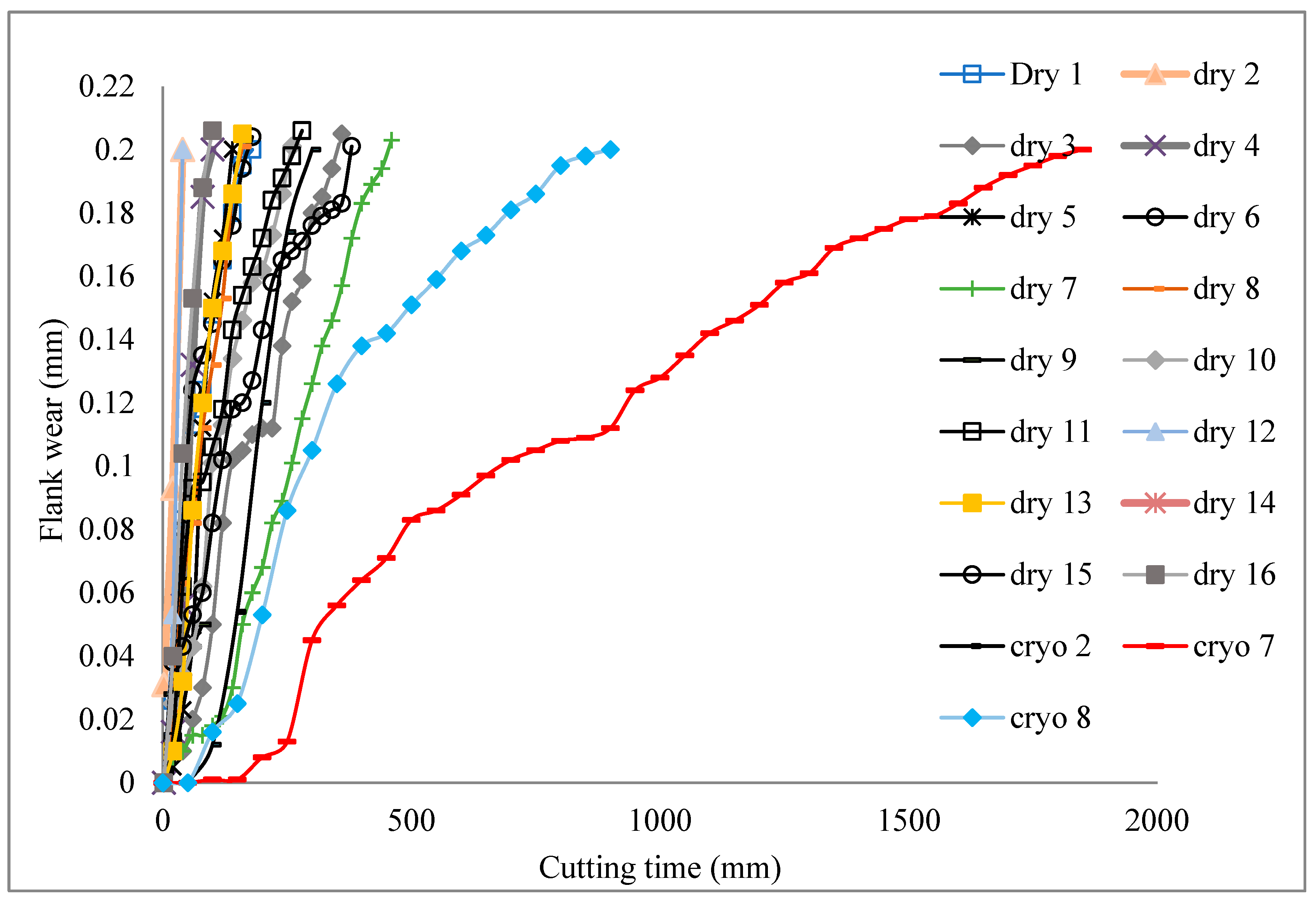
Based on the findings from the experimental work carried out under the full factorial design (L16) at various cutting speeds, feed rates, and depths of cut, a graph of flank wear versus cutting time for dry and selected cryogenic cooling was constructed as shown in Figure 3. It was discovered that the optimum cutting parameters occurred at the cutting speed of 900 m/min, feed rate of 0.02 mm/tooth, axial depth of cut of 0.3 mm, and radial depth of cut of 40 mm (Experiment number 7). This was evidenced from the graph as at this specific cutting parameter, the highest cutting time of 1864 min was achieved at VBmax of 0.21 mm under cryogenic cooling. In contrast, for dry machining, at cutting speed 1300 m/min, feed rate of 0.02 mm/tooth, axial depth of cut of 0.2 mm, and radial depth of 40 mm (Experiment number 2), the tool life lasted only 30 min. According to Wang et al. [8], cryogenic conditions can quadruple service life with negligible negative impact of wear to improve surface quality using a high speed machining regime [8].
When examining the tool wear curve for Experiment 7, three distinct regions were observed during its machining process, namely initial (or preliminary) wear region, steady wear region and rapid wear region. However, only one region, rapid wear, could be detected from the tool wear curve for Experiment 2. This shows significant improvement in cutting time or tool life for Experiment 7. Thus, cutting speed is a significant parameter affecting tool life as compared to feed rate and depth of cut under dry conditions for this range of milling parameters.
Figure 4 shows images of the worn tools at the nose region for Experiments 7 and 2. More severe wear was observed at the cutting tool edge for Experiment 2 than in Experiment 7. The cutting edge for Experiment 2 experienced notching and suffered from catastrophic failure, while chipping or flaking was observed in Experiment 7. Thus, machining of AZ91D at high cutting speeds revealed notch wear on the flank face in Experiment 2 and chipping or flaking in Experiment 7. Similar phenomena were observed [18] in milling of Inconel 718 at a high cutting speed regime that were a result of the local high temperatures areas which were a key factor affecting the tool wear rate.
Based on the results obtained for the tool life study and observations of wear on the cutting tool, it can be stated that the cutting parameters used in Experiment 7 (cutting speed of: 900 m/min; feed rate: 0.02 mm/tooth; axial depth of cut: 0.3 mm; radial depth of cut; 40 mm) are recommended to achieve maximum cutting time and gradual tool wear. Analysis of variance (ANOVA) for tool life under dry machining conditions is shown in Table 5.
Table 5 shows that all studied variables (cutting speed, feed rate, axial, and radial depth of cut) were significant to tool life, with R-sq of 75%. ANOVA could not be performed for cryogenic cooling conditions since only three experiments had been conducted.

3.2. Comparison of Carbide Cutting Tool Performance under Dry and Cryogenic Conditions

Three cutting conditions, Experiments 2, 7, and 8, were selected for more detailed analysis on performance comparison of the carbide cutting tool under dry and cryogenic conditions. Only three cutting conditions were looked into due to cost and time constraints in conducting the experimental work. Figure 5 shows the comparison of these experimental runs.
Referring to the results in Figure 5, initial tool wear under dry conditions was higher in comparison to cryogenic conditions. A small region of steady state for tool wear in dry conditions was observed as compared to cryogenic cutting conditions. Aggresive progression of tool wear was observed for dry conditions in Experiment 2, where tool wear rapidly reached VBmax of 0.2 mm after 30 min of machining, leading to its end of tool life. The time taken to reach maximum wear specified by VBmax of 0.2 mm in machining under dry conditions was around ¼ of the machining time taken under cryogenic cutting conditions. Cryogenic cooling provided the longest steady state region and overall cutting time; hence, liquid nitrogen profoundly enhances machining processes and protects cutting tools against rapid tool wear.
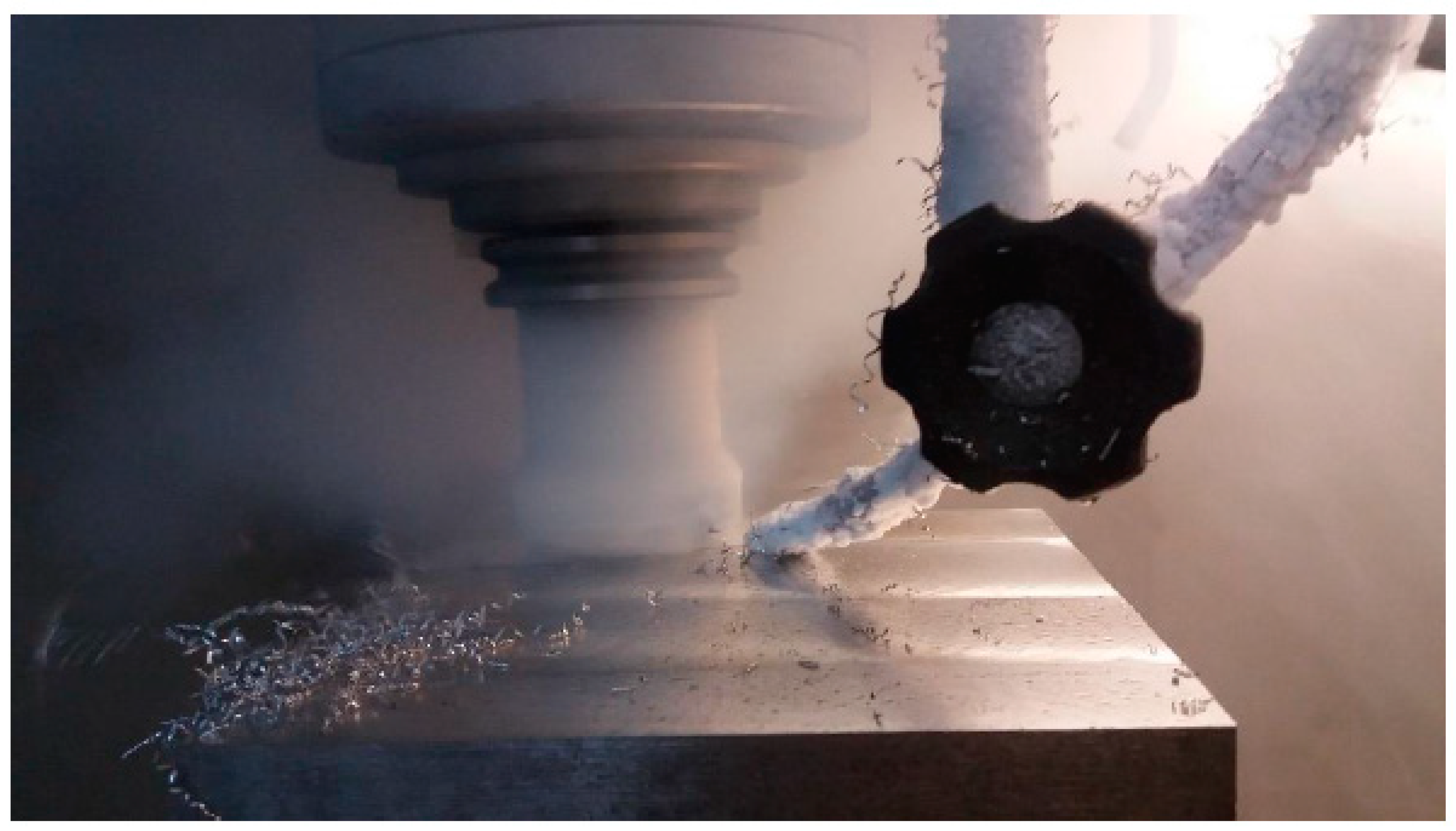
During the machining process, heat is generated due to friction between tool flank and workpiece, and friction of chip on tool rake face, causing plastic deformation of metal at the shear region [19]. While most of the generated heat is carried away by the chip, a slight amount is absorbed by the surroundings, with the remaining absorbed by the tool and workpiece. Since thermal conductivity of magnesium alloy is relatively low as compared to carbon steel, temperatures at the tool chip interface will increase rapidly. Thus, when applying cryogenic coolant to the machining zone, the heat is removed causing significant temperature reduction at the cutting zone. Therefore, cryogenic cooling allows for decreased tool wear and increased tool life as similarly found by Kumar et al. [20].
Tool life for the selected experiments conducted in milling of AZ91D under both dry and cryogenic cooling has been shown in Figure 6. Experiment 7 in cryogenic cooling clearly demonstrated the longest tool life of 1864 min, while the lowest tool life of 30 min occurred for Experiment 2 under dry conditions. Increments of tool life in cryogenic cooling were observed; more than 8× in Experiment 2; 4× more in Experiment 7; and 5× more in Experiment 8. These results were similar to Wang et al. [8], who reported a four-time increase of tool life in cryogenic conditions. Kaynak et al. [9] also stated that cryogenic cooling had reduced tool-wear rate at high cutting speeds. This suggests that cryogenic cooling is the best option for controlling progressive flank wear, hence providing a sustainable working environment in controlling dimensional deviations of AZ91D.
Flank wear for Experiments 2, 7, and 8 observed under optical microscope occurred predominantly at the nose area of the cutting tool for both dry and cryogenic cutting conditions as shown in Figure 7. Most wear was due to fracturing at the cutting edge as well as notching, especially under dry machining as seen in Figure 7c.
Figure 8, Figure 9 and Figure 10 show the tool wear experienced by the cutting conditions of Figure 7 at higher magnification. Figure 8a,b shows wear that occurred on the flank face indicating flaking of the carbide material and sticking of melted chips. The flaking was not severe, possibly due to cryogenic cooling that managed to reduce the cutting temperature. EDAX in Figure 8c indicated that tungsten carbide was the major constituent followed by oxygen. However, for Figure 8d,e, fracturing by micro cracks had been observed with EDAX analysis in Figure 8f, indicating the occurrence of oxidation with oxygen constituents at 41.8%. The occurrence of wear on the crater face was due to solid state diffusion of constituents of the tool material into the adherent chip material, subsequently torn and transported by the underside of the fresh flowing chips as similarly stated by Venugopal et al. [21].
Figure 9 shows wear on the cutting edge for Experiment 8. Flaking was observed under cryogenic cooling, but it was not severe. EDAX analysis showed that oxidation occurred on the chips deposited. High temperatures that were generated were most probably due to the high feed rate (0.05 mm/tooth) and high cutting speeds (1300 m/min) utilized under this machining condition. Abrasion also occurred but was not severe and cavitation appeared at several locations. This three-body abrasion occurs when a small carbide particle lodges between two rubbing surfaces and abrades the flank surface, as similarly observed by Ghani and Che Haron [22] in milling of Inconel 718 using carbide tools. This wear phenomenon was similarly observed under dry cutting conditions. This situation may have been due to the intact contact between the chips–tool interface that rendered the application of LN2 ineffective.
It can be concluded from the analysis of these wear phenomena in Figure 7, Figure 8 and Figure 9 that at cutting speed of 900 m/min and feed rate of 0.02 mm/tooth, the heat generated does not cause severe damage on the cutting edge, i.e., LN2 is effective in reducing cutting temperatures. However, at higher cutting speeds of 1300 m/min, for both feed rates of 0.02 and 0.05 mm/tooth, LN2 is ineffective in reducing cutting temperatures. This goes against previous research [23,24] that found that cryogenic cooling is effective at higher than lower cutting speeds. This may be due to the condition of contact at the chips–tool interface and in some cases, the inability of LN2 to penetrate the working region, rendering its application ineffective.

3.3. Surface Roughness

Surface roughness (Ra) values for each experiment at the beginning of cut has been shown in Figure 10. Based on the graph, dry machining yielded the lowest Ra value at 0.066 µm as observed from Experiment 15, while the lowest Ra value for cryogenic machining was observed from Experiment 7 at 0.091 µm. Machining under dry conditions improved surface finish by up to 14%; however, chips sticking to the rake face may have been the reason for unstable surface roughness readings. Comparatively, Experiment 7 yielded optimum parameter readings under tool life dry machining, but the surface roughness achieved was at 0.105 µm, which was higher than the measured surface roughness obtained from Experiment 15. However, tool life obtained from Experiment 15 was only 380 min.
Figure 10 shows improved surface roughness in the machining process by utilizing liquid nitrogen (LN2) cooling for Experiments 2 and 7 by 24.2% and 13.3%, respectively. However, machining under dry condition for Experiment 8 showed a 26.9% improvement than under cryogenic conditions. Similarly, better Ra was observed under other dry machining conditions such as in Experiments 3 and 10 as compared to cryogenic cooling. The larger feed rate used in these experiments may have had a more dominant influence in improving surface roughness as compared to cryogenic cooling. Increasing feed rate will increase material removal rate at a specific speed but will cause increased friction and will influence measurements of the machined surface [25]. Hence, the cooling condition and feed per tooth are the most vital factors in achieving a good surface finish [14].
In general, all measured Ra were below 0.2 µm, which resulted in mirror-like surfaces under both dry and cryogenic conditions which are required for precision components. According to Engineering [26], 0.1 µm ≤ Ra ≤ 0.2 µm is equivalent to N3–N4 (superfinishing to ground finishes). Even though notching was observed as in Figure 7f, the measured Ra value was not affected. When notch wear occurs at the DOC line, a flank profile is formed on the surface [18]. However, the defect surface was eliminated with a new cut, leaving the flank defect unseen. Furthermore, continuous application of LN2 is expected to produce or maintain good surface roughness. According to Pu et al. [12], better surface roughness is achieved by applying liquid nitrogen to the cutting zone, resulting in reduced cutting temperatures. In addition, Denish et al. [25] stated that low temperatures will induce brittle behavior in the magnesium alloy, thereby producing short and discontinuous chips. Reduced temperatures at the cutting zone can reduce chip melting at the machined surface of the magnesium alloy and the cutting tool edge, hence improving surface finish during cryogenic machining. The flow of liquid nitrogen will also help to flush away chips from the finished surface and act as a dry lubricant, which could be one of the reasons for obtaining good Ra. Dhar and Kamruzzaman [27] also reported on the same beneficial effects of cryogenic machining on surface roughness.
Analyses of variance (ANOVA) for surface roughness in dry and cryogenic conditions are shown in Table 6 and Table 7, respectively. These tables show that feed rate and radial depth of cut significantly affected surface roughness both under dry and cryogenic conditions, whereas cutting speed and axial depth of cut were not significant with R-sq at 88% and 80% for dry and cryogenic conditions, respectively.
Carou et al. [28] reported that feed rate was the main contributing factor affecting all machining tests in intermittent turning of UNS M11917 magnesium alloy. Othman et al. [29] also found that feed rate was the most significant factor in turning Al-Si alloy. In this study, in addition to feed rate, radial depth of cut was also a significant factor in the machining experiments. According to Shen et al. [30], high radial depth increases vibrations and deteriorates machining quality during face milling of AISI304 stainless steel with cemented carbide milling cutters. Investigations carried out by Ribeiro et al. [31] revealed that radial cutting depth and the interaction between radial and axial depth of cut are the most relevant parameters affecting surface finish in milling hardened steel.

4. Conclusions

This study compared cryogenic cooling and dry cutting conditions for high-speed milling of AZ91D magnesium alloy. Based on the experimental results and detailed observations from this study, the following can be concluded:
  • The optimum machining condition identified from this range of study was at cutting speed of 900 m/min, feed rate of 0.02 mm/tooth, axial depth of cut at 0.3 mm, and radial depth of cut at 40 mm, in which the maximum tool life of 1864 min was achieved;
  • Tool life is significantly improved in cryogenic cooling as compared to when dry machining at more than eight times in certain cases especially at a lower cutting speed of 900 m/min.
  • Mirror-like machined surfaces of N3-N4 finish levels were produced both in cryogenic and dry conditions, but with better surface finish obtained in cryogenic cooling;
  • Analysis of the wear mechanism revealed that less severe wear was observed while utilizing LN2 cooling as compared to dry machining. The wear mechanisms observed were notching, solid state diffusion cavitation, fracturing, and flaking of the carbide tools;
  • The application of cryogenic and dry cutting conditions leads to a sustainable manufacturing practice that is environmentally friendly.
For future work, the effects of cutting speeds of less than 1000 m/min will be studied in detail since they are expected to result in better machining output.

Author Contributions

Writing—original draft preparation, data curation, M.S.M.R. and J.A.G.; funding acquisition, N.J. and J.A.G.; Supervision, J.A.G. and C.H.C.H. All authors have read and agreed to the published version of the manuscript.

Funding

This research was funded by the Deputyship for Research and Innovation, Ministry of Education in Saudi Arabia (IF2/PSAU/2022/01/22123).

Institutional Review Board Statement

Not applicable.

Informed Consent Statement

Not applicable.

Data Availability Statement

The data used to support the findings of this study are included within the article.

Acknowledgments

The authors extend their appreciation to the Deputyship for Research and Innovation, Ministry of Education in Saudi Arabia for funding this research work through the Project number (IF2/PSAU/2022/01/22123).

Conflicts of Interest

The authors declare no conflict of interest.

References

  1. Gray, J.E.; Luan, B.J. Protective coatings on magnesium and its alloys—A critical review. J. Alloys Compd. 2002, 336, 88. [Google Scholar] [CrossRef]
  2. Song, G.; Bowles, A.L.; StJohn, D.H. Corrosion resistance of aged die cast magnesium alloy AZ91D. Mater. Sci. Eng. A 2004, 366, 74–86. [Google Scholar] [CrossRef]
  3. Musfirah, A.H.; Jaharah, A.G. Magnesium and Aluminum Alloys in Automotive Industry. J. Appl. Sci. Res. 2012, 8, 4865–4875. [Google Scholar]
  4. Ghassemieh, E. Materials in automotive application, state of the art and prospects. In New Trends and Developments in Automotive Industry; InTech; BoD—Books on Demand: Norderstedt, Germany, 2011. [Google Scholar]
  5. Ghosh, N.; Ravi, Y.B.; Patra, A.; Mukhopadhyay, S.; Paul, S.; Mohanty, A.R.; Chattopadhyay, A.B. Estimation of tool wear during CNC milling using neural network-based sensor fusion. Mech. Syst. Signal Process. 2007, 21, 466–479. [Google Scholar] [CrossRef]
  6. Shi, K.; Ren, J.; Zhang, D.; Zhai, Z.; Huang, X. Tool wear behaviors and its effect on machinability in dry high-speed milling of magnesium alloy. Int. J. Adv. Manuf. Technol. 2017, 90, 3265–3273. [Google Scholar] [CrossRef]
  7. Bermingham, M.J.; Kirsch, J.; Sun, S.; Palanisamy, S.; Dargusch, M.S. New observations on tool life, cutting forces and chip morphology in cryogenic machining Ti-6Al-4V. Int. J. Mach. Tools Manuf. 2011, 51, 500–511. [Google Scholar] [CrossRef]
  8. Wang, F.; Li, L.; Liu, J.; Shu, Q. Research on tool wear of milling nickel-based superalloy in cryogenic. Int. J. Adv. Manuf. Technol. 2017, 91, 3877–3886. [Google Scholar] [CrossRef]
  9. Kaynak, Y.; Karaca, H.E.; Noebe, R.D.; Jawahir, I.S. Tool-wear analysis in cryogenic machining of NiTi shape memory alloys: A comparison of tool-wear performance with dry and MQL machining. Wear 2013, 306, 51–63. [Google Scholar] [CrossRef]
  10. Hou, J.; Zhao, N.; Zhu, S. Influence of cutting speed on flank temperature during face milling of magnesium alloy. Mater. Manuf. Process. 2011, 26, 1059–1063. [Google Scholar] [CrossRef]
  11. Tomac, N.; Tonnessen, K.; Rasch, F.O. Formation of flank build-up in cutting magnesium alloys. CIRP Ann.-Manuf. Technol. 1991, 40, 79–82. [Google Scholar] [CrossRef]
  12. Pu, Z.; Outeiro, J.C.; Batista, A.C.; Dillon, O.W.; Puleo, D.A.; Jawahir, I.S. Enhanced surface integrity of AZ31B Mg alloy by cryogenic machining towards improved functional performance of machined components. Int. J. Mach. Tools Manuf. 2012, 56, 17–27. [Google Scholar] [CrossRef]
  13. Akhyar, G.; Harun, S.; Hamni, A. Surface Roughness Values of Magnesium Alloy AZ31 When Turning by Using Rotary Cutting Tool. INSIST 2016, 1, 54–59. [Google Scholar] [CrossRef] [Green Version]
  14. Chirita, B.A.; Tampu, N.C. Analysis of Surface Roughness for High Speed Milling of a Magnesium Alloy Part. Adv. Mater. Res. 2014, 837, 33–38. [Google Scholar] [CrossRef]
  15. Guo, Y.B.; Salahshoor, M. Process mechanics and surface integrity by high-speed dry milling of biodegradable magnesium–calcium implant alloys. CIRP Ann.-Manuf. Technol. 2010, 59, 151–154. [Google Scholar] [CrossRef]
  16. ISO 8688-2(E); Tool Life in Milling-Part 2: End Milling. International Organization for Standardization: Geneva, Switzerland, 1989.
  17. Poulachon, G.; Bandyopadhyay, B.P.; Jawahir, I.S.; Pheulpin, S.; Seguin, E. The influence of the microstructure of hardened tool steel workpiece on the wear of PCBN cutting tools. Int. J. Mach. Tool Manuf. 2003, 43, 139–144. [Google Scholar] [CrossRef]
  18. Hadi, M.A.; Ghani, J.A.; Che Haron, C.H. Effect of cutting speed on the carbide cutting tool in milling Inconel 718 alloy. J. Mater. Res. 2016, 31, 1885–1892. [Google Scholar] [CrossRef]
  19. Khan, A.A.; Mirghani, I.A. Improving tool life using cryogenic cooling. J. Mater. Process. Technol. 2008, 196, 149–154. [Google Scholar] [CrossRef]
  20. Kumar, K.V.; Kalyan, B.S.; Choudhury, S.K. Investigation of tool wear and cutting force in cryogenic machining using design of experiments. J. Mater. Process. Technol. 2008, 203, 95–101. [Google Scholar] [CrossRef]
  21. Venugopal, K.A.; Paul, S.; Chattopadhyay, A.B. Tool wear in cryogenic turning of Ti-6Al-4V alloy. Cryogenics 2007, 47, 12–18. [Google Scholar] [CrossRef]
  22. Ghani, J.A.; Che Haron, C.H. Wear mechanism of coated and uncoated carbide cutting tool in machining process. J. Mater. Res. 2016, 31, 1873–1879. [Google Scholar] [CrossRef] [Green Version]
  23. Raof, N.A.; Ghani, J.A.; Che Haron, C.H. Machining-induced grain refinement of AISI 4340 alloy steel under dry and cryogenic conditions. J. Mater. Res. Technol. 2019, 8, 4347–4353. [Google Scholar] [CrossRef]
  24. Halim, N.H.A.; Haron, C.H.C.; Ghani, J.A.; Azhar, M.F. Tool wear and chip morphology in high-speed milling of hardened Inconel 718 under dry and cryogenic CO2 conditions. Wear 2019, 426, 1683–1690. [Google Scholar] [CrossRef]
  25. Dinesh, S.; Senthilkumar, V.; Asokan, P.; Arulkirubakaran, D. Effect of cryogenic cooling on machinability and surface quality of biodegradable ZK60 Mg alloy. Mater. Des. 2015, 87, 1030–1036. [Google Scholar] [CrossRef]
  26. An Engineering. Surface Texture Equivalents. Available online: https://www.an-engineering.co.uk/surface-finish-chart/ (accessed on 11 August 2021).
  27. Dhar, N.R.; Kamruzzaman, M. Cutting temperature, tool wear, surface roughness and dimensional deviation in turning AISI-4037 steel under cryogenic condition. Int. J. Mach. Tools Manuf. 2007, 47, 754–759. [Google Scholar] [CrossRef]
  28. Carou, D.; Rubio, E.M.; Lauro, C.H.; Davim, J.P. Experimental investigation on surface finish during intermittent turning of UNS M11917 magnesium alloy under dry and near dry machining conditions. Meas. J. Int. Meas. Confed. 2014, 56, 136–154. [Google Scholar] [CrossRef]
  29. Othman, K.; Ghani, J.A.; Juri, A.; Mohd, M.S.R.; Kassim, S.; Haron, C.H.C. Optimization of Tool Life and Surface Roughness for Hypereutectic Al—Si Alloys in Face Milling. J. Mech. Eng. 2020, 17, 27–44. [Google Scholar] [CrossRef]
  30. Shen, Y.; Chen, Y.; Zhang, L.; Fang, H.; Pang, J.; Liu, M.; Wang, S.; Ma, X.; Zhang, J.; Liu, Z. Effect of radial depth on vibration and surface roughness during face milling of austenitic stainless steel. Trans. Tianjin Univ. 2011, 17, 336–339. [Google Scholar] [CrossRef]
  31. Ribeiro, J.E.; Cesar, M.B.; Lopes, H. Optimisation of Machining Parameters to Improve the Surface Quality. Procedia Struct. Integr. 2017, 5, 355–362. [Google Scholar] [CrossRef]
Figure 1. Liquid nitrogen delivery during the machining process.
Sustainability 15 03760 g001
Figure 2. Insert dimensions.
Sustainability 15 03760 g002
Figure 3. Flank wear (mm) vs. cutting time (min) for both dry and cryogenic machining based on full factorial design of study.
Sustainability 15 03760 g003
Figure 4. Nose region of worn tools for Experiment 7: (a): chipping or flaking and Experiment 2 (b): notching on flank face. Scale bar at 0.2 mm.
Sustainability 15 03760 g004
Figure 5. Flank wear progression for both dry and cryogenic conditions.
Sustainability 15 03760 g005
Figure 6. Comparison of tool life under dry and cryogenic conditions.
Sustainability 15 03760 g006
Figure 7. (a) Experiment 2 in cryogenic; (b) Experiment 7 in cryogenic; (c) Experiment 8 in cryogenic; (d) Experiment 2 in dry; (e) Experiment 7 in dry; (f) Experiment 8 in dry.
Sustainability 15 03760 g007
Figure 8. Experiment 2 (ac) cryogenic cooling, (df) dry condition.
Sustainability 15 03760 g008
Figure 9. Experiment 8 (ac) cryogenic cooling, (df) dry condition.
Sustainability 15 03760 g009aSustainability 15 03760 g009b
Figure 10. Surface roughness under dry and cryogenic conditions.
Sustainability 15 03760 g010
Table 1. AZ91D chemical composition.
Chemical Composition (%)
AlZnMnCuNiSiFeMg
8.730000.690000.200000.001700.000810.017000.00100Balance
Table 2. Cutting tool geometry.
ItemsValue
Length, l9.52 mm
Thickness, s3.97 mm
Clearance angle, α15.0°
Wiper cutting edge length, b1.2 mm
Corner radius, r0.3 mm
Table 3. Full factorial design of experiment (L16).
Experiment No.Cutting Speed (m/min)Feed Rate (mm/tooth)Axial Depth of Cut (mm)Radial Depth of Cut (mm)
19000.020.340
213000.020.240
39000.050.310
413000.050.240
59000.020.240
69000.050.340
79000.020.340
813000.050.310
99000.020.310
109000.050.210
1113000.020.210
1213000.050.340
139000.020.340
149000.020.210
1513000.020.310
1613000.050.240
Table 4. Experimental results for tool life and surface roughness.
Exp. No.Surface Roughness—Dry (µm)Tool Life—Dry (min)Surface Roughness—Cryogenic (µm)Tool Life—Cryogenic (min)
10.1151800.119
20.140300.106265
30.1223500.161
40.1611000.128
50.1121460.101
60.1801800.136
70.1054600.0911864
80.1151500.146867
90.0723800.139
100.1122600.148
110.0702800.131
120.171400.116
130.0821600.152
140.0683000.126
150.0663800.136
160.180900.120
Table 5. ANOVA for tool life under dry machining conditions.
SourceDFAdj SSAdj MSF-Valuep-Value
   Cutting speed (m/min)144,73244,7327.630.018
   Feed rate (mm/tooth)142,64242,6427.280.021
   Axial depth of cut (mm)135,53235,5326.060.032
   Radial depth of cut (mm)166,82266,82211.400.006
Error1164,4755861
Total15254,204
Table 6. ANOVA for surface roughness in dry machining.
SourceDFAdj SSAdj MSF-Valuep-Value
Cutting speed (m/min)10.0000600.0000600.320.584
Feed rate (mm/tooth)10.0087890.00878946.540.000
Axial depth of cut (mm)10.0000280.0000280.150.710
Radial depth of cut (mm)10.0130530.01305369.120.000
Error110.0020770.000189
Total150.024007
Table 7. ANOVA for surface roughness in cryogenic cooling.
SourceDFAdj SSAdj MSF-Valuep-Value
   Cutting speed (m/min)10.0000080.0000080.110.743
   Feed rate (mm/tooth)10.0015610.00156121.210.001
   Axial depth of cut (mm)10.0000720.0000720.970.345
   Radial depth of cut (mm)10.0030820.00308241.870.000
Error110.0008100.000074
Total150.005533
Disclaimer/Publisher’s Note: The statements, opinions and data contained in all publications are solely those of the individual author(s) and contributor(s) and not of MDPI and/or the editor(s). MDPI and/or the editor(s) disclaim responsibility for any injury to people or property resulting from any ideas, methods, instructions or products referred to in the content.

