Article

Substantiation of the Direction for Mining Operations That Develop under Conditions of Shear Processes Caused by Hydrostatic Pressure

1
Belt and Road Initiative Centre for Chinese-European Studies (BRIICES), Guangdong University of Petrochemical Technology, Maoming 525000, China
2
Department of Surface Mining, Dnipro University of Technology, Yavornytskoho Ave., 19, 49005 Dnipro, Ukraine
3
Mining and Metallurgical Institute Named after O.A. Baikonurov, Satbayev University, Almaty 50013, Kazakhstan
*
Author to whom correspondence should be addressed.
Sustainability 2023, 15(22), 15690; https://doi.org/10.3390/su152215690
Submission received: 27 September 2023 / Revised: 25 October 2023 / Accepted: 3 November 2023 / Published: 7 November 2023

Abstract

:
This research is aimed to substantiate the optimally safe direction for mining operations developing in the conditions of shear processes under hydrostatic pressure influence when mining the Zavalivskyi Graphite Deposit. Using a graphical–analytical method, the slope stability index of the Pivdenno–Skhidnyi open-pit walls in the Zavalivskyi deposit and the safe distance for placing mining equipment have been determined. This method involves constructing a calculation scheme for each studied open-pit wall area based on the determined parameters by algebraically adding forces along a curvilinear shear surface, taking into account hydrostatic pressure within a possible collapse prism. During the research, factors have been identified that influence the optimal direction for stripping and mining operations developing under conditions of shear processes caused by flooding of lower horizons at the Zavalivskyi Graphite Plant. It has been revealed that the determining factor when choosing the direction for the development of mining operations is the safety factor of the open-pit working wall, ranging from 0.9 to 2.71 in the studied areas. Moreover, according to current normative documents, this indicator should not be less than 1.3. It has been determined that a promising direction for the development of mining operations in the Pivdenno–Skhidnyi open-pit mine is its south-western, western, and north-eastern areas, with a length of 556 m and a safe size for placing mining equipment of 27.12–32.54 m. Recommendations and measures for conducting mining operations have been developed to ensure the stable condition of the open-pit walls.

1. Introduction

In recent years, there has been a trend toward increasing demand for electric batteries due to the mass production of electric vehicles, electric scooters, electric bicycles, sources of uninterrupted power supply, etc. [1,2]. For example, in 2022, electric vehicle sales increased by 68% compared to 2021 [3]. In total, in 2022, manufacturers sold more than 10 million electric vehicles, which is about 10% of all vehicles sold [4,5]. China and the USA dominate global electric vehicle (EV) sales [6,7], with Norway notably leading in terms of EV market penetration, where nearly 75% of vehicles sold in 2020 were electric [8,9].
The International Energy Agency predicts that by 2030, the share of electric vehicles in the automobile market will increase to 60% [10,11]. That is, in seven years, more vehicles with electric motors will be sold than those with internal combustion engines. The trend of increasing sales of electric vehicles is presented in Figure 1.
The popularity of electric vehicles is partly a consequence of many governments’ policies to reduce environmental pollution from conventional vehicles. In China, electric vehicles accounted for 19% of new vehicle sales in 2022, according to data from LMC Automotive research group. In the European Union this figure was 11%, in the USA—5.8%. In 2022, 4.4 million of only battery-powered electric vehicles and 1.5 million plug-in hybrid electric vehicles were sold. Consequently, China accounts for more than half of all electric vehicles sold worldwide. China’s Ministry of Industry and Technology, which oversees the automobile industry, plans to increase the share of electric vehicle sales to 40% by 2030 [12,13].
The most common material used in batteries is lithium [14]. And lithium-ion batteries are the most efficient to use. Nevertheless, lithium-ion batteries have several disadvantages: high cost, narrow operating temperature range (to operate efficiently at low temperatures, the battery must be heated, which results in its faster discharge), a characteristic “aging” process entails a decline in performance with age, and it is not acceptable for the battery to be completely discharged or overcharged [15]. Graphite is used to increase the power and capacity of lithium-ion batteries. Graphite is a mineral of the native semimetal class, the most stable crystalline form of carbon in the earth’s crust. Graphite-based materials (graphite-LiMO2) are commonly used as substitutes for pure metal anodes [16,17].
Ukraine has a powerful raw material base of graphite ores. The State Balance of Mineral Reserves of Ukraine includes six graphite deposits, of which only two are currently being mined: Zavalivskyi and Balakhiv graphite deposits. The recorded graphite reserves in Ukraine are about 18 million tons. There is also potential to increase graphite reserves, the resources of which are estimated at 50–100 million tons. The depth of graphite ore occurrence ranges within 10–80 m. Graphite-containing rocks form sheet-like and lens-shaped bodies up to 300 m thick; their length is from 500 to 1500 m, sometimes up to 3.5–5.0 km. Graphite is flaky, with content in ores from 2.5 to 20%, rarely up to 30% [18,19].
The Zavalivskyi Graphite Deposit is one of the largest in Europe. According to official data, as of 2020, 5.2 thousand tons of graphite was mined in Ukraine (this figure is 0.5% of total global production). A wide range of graphite grades are produced for various industries (crucible, elemental, foundry, electric coal, battery, pencil, friction metal–ceramic, powder, special low-ash, etc.). The production of foundry, crucible, and elemental graphite predominates. The quality of graphite products of Ukrainian enterprises meets world standards and is exported to other countries [20,21]. The development of mineral deposits is a particularly urgent task for providing the possibilities and prospects for innovative investment development in the post-war economy of Ukraine [22,23].
Surface mining of deposits is associated with the influence of technical means on the rock mass [24]. In order for the equipment to operate efficiently and be in compliance with safe working conditions, it is necessary to be able to predict the rock mass state in the open-pit walls and in dumps, both internal and external. In this case, it is necessary to ensure the safety of facilities, structures, and mechanisms located in the zone influenced by the prism of possible slope collapses [25]. It is also important to consider the hydrogeological conditions in which the rock mass is located [26,27]. This affects the physical–mechanical properties of rocks, which leads to the loss of their stability. In such conditions, mining operations can be conducted in the mode of controlled deformations of benches and slopes. It is therefore important to assess the stability of benches, walls of open pits, and dumps, taking into account the mining depth, engineering–geological factors, seismic and tectonic processes, mining–technical conditions, and hydrodynamic pressure [28,29].
Mining of mineral raw materials in difficult conditions of shear processes under the influence of hydrostatic pressure should be performed taking into account technologies that meet the following requirements: the use of special techniques and methods for performing blasting operations that will ensure the minimization of seismic impact on adjacent facilities, including mine workings that are in a stressed state [30,31]; maximum use of the mined-out open-pit space and complete mining of mineral resources [32,33]; the use of rational transportation schemes that minimize the specific energy intensity of the rock mass transportation processes [34]; ensuring dewatering of the mined-out space and drainage operatrions, which to the greatest extent ensure the safe conduct of mining operations, taking into account the coefficient of the rock mass stability under the influence of hydrodynamic pressure during flooding of lower horizons [35,36], as well as the natural or close to it hydrological regime of the area without significant changes in the direction of supplying enterprises and the population with volumes of drinking and process water [37]; conducting reclamation and revitalization of lands disturbed by mining operations to the most environmentally acceptable landscapes of territories with their subsequent recreation [38,39]. It should also be noted that it is necessary to comply with the environmental aspects of mining operations, taking into account the development of clean technologies (Clean Coal Technologies) when mining deposits of different types of origin and using technologies for their mining [40,41]. The above-mentioned provisions lead to the urgency of substantiating the optimal direction for mining operations developing under conditions of shear processes caused by flooding of lower horizons influenced by hydrostatic pressure by determining the stability index of slopes.
The results of scientific research and project development on these problems, project materials for the study of geological and hydrogeological conditions of the Zavalivskyi Graphite Deposit, and studies and recommendations on the parameters of the southern and northern walls and the boundary contours of the Pivdenno–Skhidnyi open-pit mine are studied. Also, issues related to the mining operations developing in deep open pits, dewatering of rock masses and flooding of territories in mining regions, and the development of shear processes in technogenically disturbed masses were considered in the studies of the M.S. Polyakov Institute of Geotechnical Mechanicsof National Academy of Science of Ukraine [42,43]. The above research was carried out in the 1990s. This argues for the urgency of substantiating the optimal direction for the development of mining operations in modern conditions of shear processes, taking into account the safety factor of the open-pit working wall. It should be noted here that there are different methods for determining the safety factor [44]. At the same time, the advantage of the proposed method in this research is its simplicity and understandability for engineering and technical workers. Moreover, in the event of the detection of deformation–shear processes, it is sufficient to quickly determine the safety factor of the open-pit wall when taking measures to change the resultant slope angle of both the entire wall and individual benches.
The practice of performing mining operations in the Pivdenno–Skhidnyi open-pit mine since 1993 has revealed more than 15 shear deformations. The most notable among them were shear deformations that resulted from the mechanical suffusion of finely dispersed particles from the Baltian sand aquifer, which led to shear deformations in the thickness of upper clay layers towards the mined-out space.
Similar phenomena occurred in 1993–1996 in the north-western open-pit wall area. A stratum of loams and clays 30–40 m thick was covered by the deformation from the shear processes. The length of shear deformations along the front ranged from 100 to 200 m, the width was up to 40–50 m, and the shearing rock mass volume was from 60 to 278 thousand m3. At the same time, the intensification of shear deformations also occurred due to the accumulation of surface water in the beams, reaching the open-pit wall boundaries. In addition, in 1996, the gully thalweg was blocked by created dumps, which contributed to raising the water level above the open-pit contour. Water seeped into the loam thickness, and through the layer of heavy brownish-brown clays, which are waterproof, a sliding plane was formed, along which the shear process was manifested.
Another reason for the intensification of shear processes was the erosion of the Baltian sand bench slope by surface waters. As a result of this, rather steep slopes were formed in the sand mass, which, under the influence of groundwater seepage, were flooded, creating favorable conditions for the sliding of loams and clays of the upper layer. To stabilize the benches, a drainage trench was laid in the open pit, the bottom of which was in the clay roof.
During 1999–2000, shear deformations developed throughout almost the entire northern wall along the front up to 1000 m. At first, the slope deformations occurred only on the lower bench of soft rocks (Baltian sands) 8–10 m high. After 2.5–3 months, shear deformations spread to the upper bench, and they also covered the overburdened rock dumps located behind the open-pit edge. The volume of this large-scale landslide reached 2 million m3 of sandy–clayey rocks. With the onset of winter, with the surface freezing to 0.2–0.8 m, the intensity of development of shear processes decreased. With the freezing of the surface and shear body slope, as well as due to the cessation of infiltration of atmospheric precipitation and surface water into its internal zone, the development of deformations has completely ceased.
Quite a powerful shear process occurred in the autumn of 2007 in the central area of the northern wall. The deformed zone length reached 500 m, and the rock volume was more than 800 thousand m3. The reason for the shear deformation can be considered as due to the infiltration of atmospheric precipitation and surface water into the rock mass (the amount of annual precipitation was 610 mm, which is 60–80 mm higher than its volume in 1996–2005). In 2008, a similar deformation occurred along a 100 m long front in the north-western open-pit wall. At that time, 150 thousand m3 of rock “came to the daylight surface”, their displacements in depth reached 25 m, and deformation spread to the mass rear by only 0.5–1 m. This indicates that deformation of the near-slope rock masses occurred, from the body of which dusty particles of clay rocks were intensively carried away by infiltration waters.
From the spring of 2008 to the autumn of 2009, in the northern open-pit wall, the development of two shear processes was noted at elevations of +100.00–+3.00 m, which were formed in a complex of weathered granitoid, kaolinized, and mylonitized rocks interspersed with freshly fractured migmatites and quartzites. In the autumn of 2009, these shear deformations merged into one with a total mass volume of about 400 thousand m3.
An analysis of the conditions in which these shear deformations occurred shows that their formation is associated with the unfavorable occurrence of rock layers relative to the benches and the wall slope as a whole. That is, the natural weakening surfaces, which are the contacts of rock layers with each other, hang over the plane of their outcrop by the bench slope. Therefore, at elevated bench slope angles, the development of deformation–shear processes along the sliding planes is possible, which will coincide with the unfavorable widespread natural weakening of the rock layer contacts.
It should be noted that until 2015, deformation processes (landslides, suffusions, and overflows) were not recorded in the southern open-pit wall. According to the conclusion of experts from the geological-surveying service of the Zavalivskyi Plant, this is due to the fact that the water inflow in the southern wall area within the soft rock thickness of Baltian loams, sands, and clays is significantly less than in the northern wall. This is evidenced by the practical absence of zones and places of groundwater seepage in this wall. Similar zones occur lower in the fractured part of metamorphic rocks.
To further prepare for the mining of graphite ore reserves, the enterprise decided on long-term mining of the deposit by the Pivdenno–Skhidnyi open pit. It is planned to mine the western open-pit area with overburden horizons with elevations of +131 m, +111 m, and +101 m and mining horizons of +94 m and +86 m. Mining operations will be conducted in this area of the open pit for 6–8 years while deepening to 15 m per year. This direction for the development of mining operations will make it possible to reactivate non-workable horizons. In this regard, mining operations at deep open-pit horizons (up to ±0 m) will not be performed for 6–8 years. To increase the economic efficiency of mining operations at the Zavalivskyi Graphite Plant, it is proposed to fill the deep open-pit horizons with water up to the −19 m level. Thus, it is necessary to confirm the feasibility of changing the direction of mining operations in the open pit, provided that the functioning of its water-filled lower horizons is safe and stable.
In a previous study, the authors provided critical information to ensure the safety and efficiency of mining operations in deep open pits by establishing safe distances for mining equipment when creating internal dumps, thereby mitigating potential hazards and optimizing resource utilization [45].
The research purpose of the current study is to substantiate the direction for mining operations developing under conditions of shear processes influenced by hydrostatic pressure based on determining the open-pit working wall stability index and the safe distance for placing mining equipment. To achieve this, this paper analyzes mining operations in the Pivdenno–Skhidnyi open pit of the Zavalivskyi Graphite Deposit (Kirovohrad region, Ukraine), constructs a calculation scheme for determining the possible collapse prism parameters, determines the stability parameters for the open-pit walls most exposed to the impact of deformation processes, taking into account the physical–mechanical peculiarities and hydrogeomechanical processes, and then determines the safe distance for placing mining equipment outside the possible collapse prism boundaries.

2. Materials and Methods
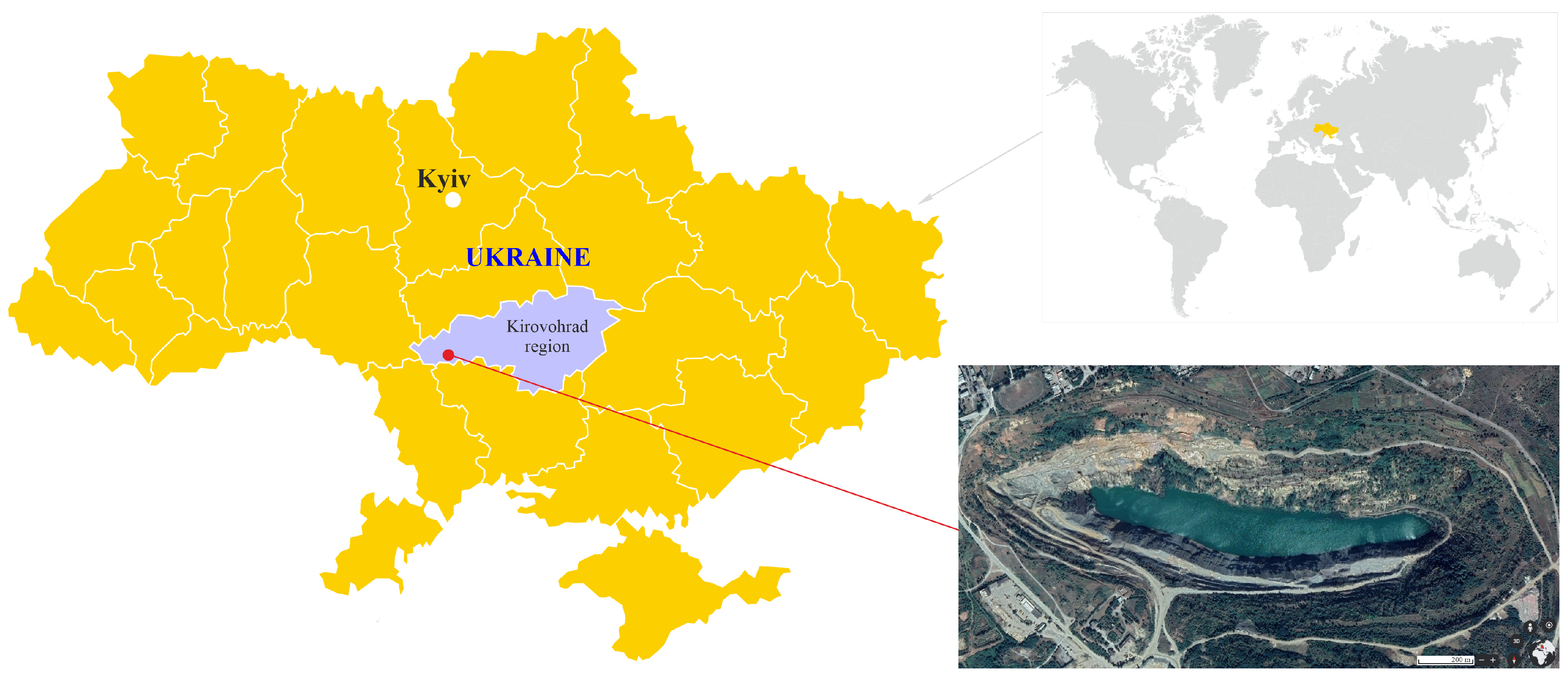
2.1. Study Area

The initial data for conducting research to optimize the direction for mining operations developing under conditions of shear processes caused by the influence of hydrostatic pressure are mining plans of geological and hydrogeological sections of the research object (Zavalivskyi Graphite Deposit). The south-eastern area of the Zavalivskyi Graphite Deposit is mined by Pivdenno–Skhidnyi open pit (Figure 2).
The open pit is located in the Pivnich ore zone, stripping its eastern area and the fold of the synclinal structure along its strike. Within the open pit along the strike, the western ore zone area has not been stripped. The deposit thickness is variable, and the incidence angle is 70–80°.
The stripping of the open-pit horizons was performed through an external central trench to the horizon of +100 m and the lower ones through a system of internal automobile declines. The deposit is mined with a two-way development of mining operations along the strike and with their deepening. The open-pit bottom is at an elevation of −41 m, while the planned elevation is at −79 m. The elevation of the upper horizons is, on average, 130 m. The mining method adopted in the open pit is excavating method using drilling-blasting operations, followed by loading into dump trucks. For the mining–technical conditions of the open pit, the transport mining system with parallel movement of the working front and the external location of the dumps is the most rational. The following equipment is used: EKG-5A excavators, KrAZ-256 B dump trucks, and SBSH-250 MH drilling rigs. Mining operations are concentrated on the lower open-pit horizons, ensuring the required volume of graphite ore production. If the safety factor is less than 1.3, then the enterprise’s geological surveying service must constantly monitor the position of both the entire wall and its individual parts (each bench). If deformation–shear processes are detected, it is necessary to reduce both the resultant slope angle of the entire wall and individual benches.
The Zavalivskyi Graphite Deposit belongs to the Teterevo–Buzka Series of metamorphic rocks located in a synclinal fold. Its wings have a north-eastern and south-western strike. The south-eastern deposit area, mined by the Pivdenno–Skhidnyi open pit, is located on the northern wing of the fold, the thickness of which is 300–400 m. The calciphyre layer thickness reaches 600–650 m.
The geological structure of the deposit includes the following: cherokite (they form the upper part of the eastern area of the open-pit northern wall), ore and non-ore gneisses (they form the western and eastern open-pit walls and the middle and lower parts of the northern wall), and calciphyres (southern open-pit wall). Table 1 shows the physical–mechanical properties of the rocks representing the Zavalivskyi Graphite Deposit. The south-eastern deposit area is characterized by three aquifers in Quaternary loams, Baltian sands, and fractured crystalline rocks.
The aquifer in forest-like loams is located in their lower area above the red-brown loams, which are impermeable. It is fed by atmospheric precipitation. There is no water filtration observed on the bench slopes. The Baltian aquifer is confined to the sands of the Baltian suite. Gray-green clays, or clayey rocks of the weathering crust of metamorphic rocks, are waterproof. Feeding is the infiltration of atmospheric precipitation through loess rocks and due to the waters of the metamorphic complex. The discharge area is the Southern Bug River valley, ravines, and gullies. The Baltian aquifer water filtration is observed in all walls, the maximum being in the northern and north-eastern walls. The crystalline rock mass water permeability is determined by the degree of fracturing, the opening of the fractures, and the presence of filler in the fractures. The maximum water permeability is observed in calciphyres, the minimum is in cherokites, and the mean is in gneisses.
Fracture waters are pressurized, and the hydrostatic pressure head above the bedrock surface is 4–6 m. There is a hydraulic connection between the Baltian aquifer and fractured aquifers. Claying of fractures is the main reason for selective high water saturation. Fracture zones are unevenly distributed to a depth of 20–50 m, less often 70–80 m. In terms of quantity, the fracture water inflow is small and does not have a significant effect on open-pit irrigation. Water inflows into the open pit are as follows: from the horizon of Baltian deposits—241 m3/hour; from the fractured zone of crystalline rocks—30 m3/hour; from atmospheric precipitation—106 m3/hour.

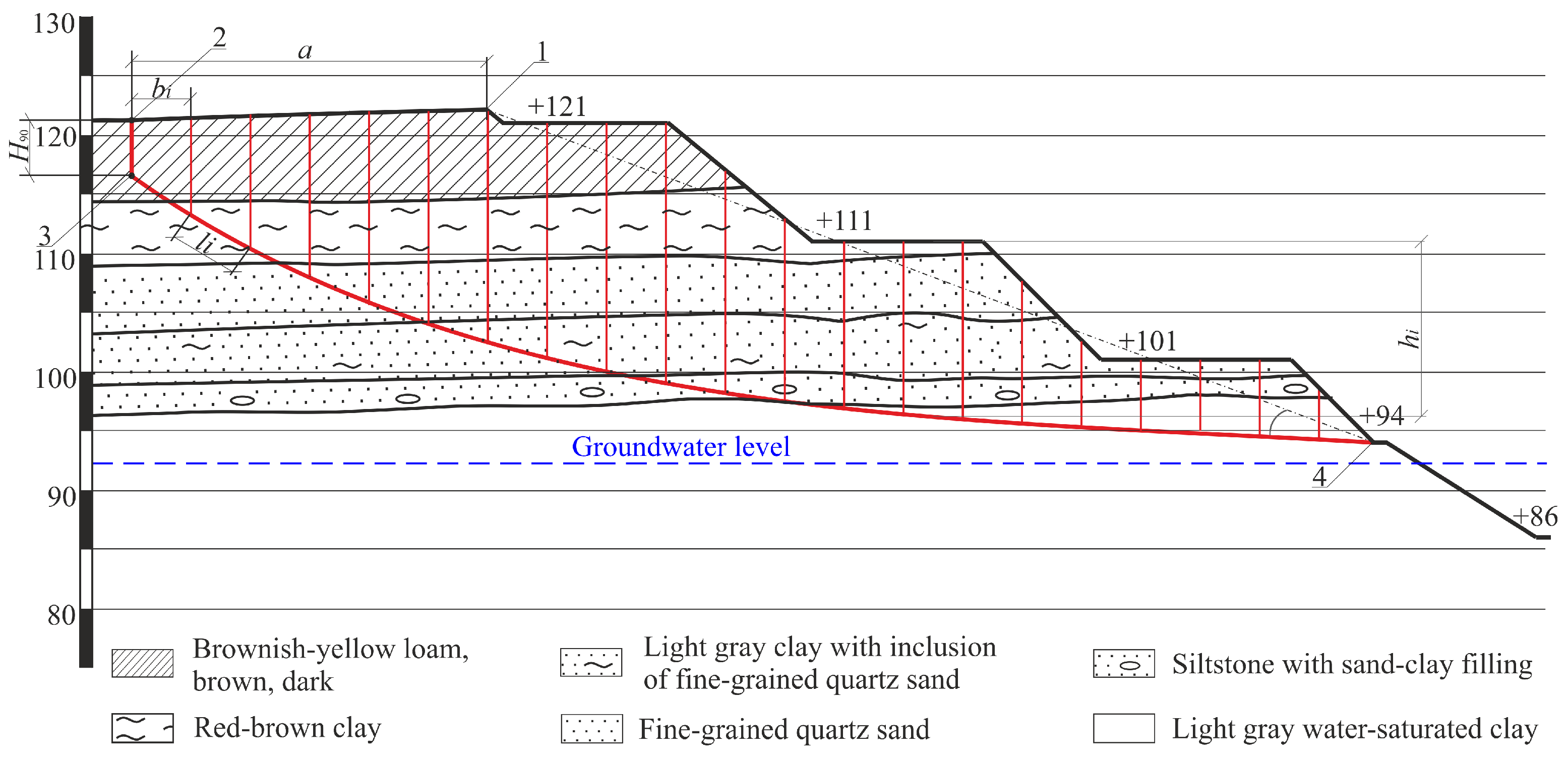
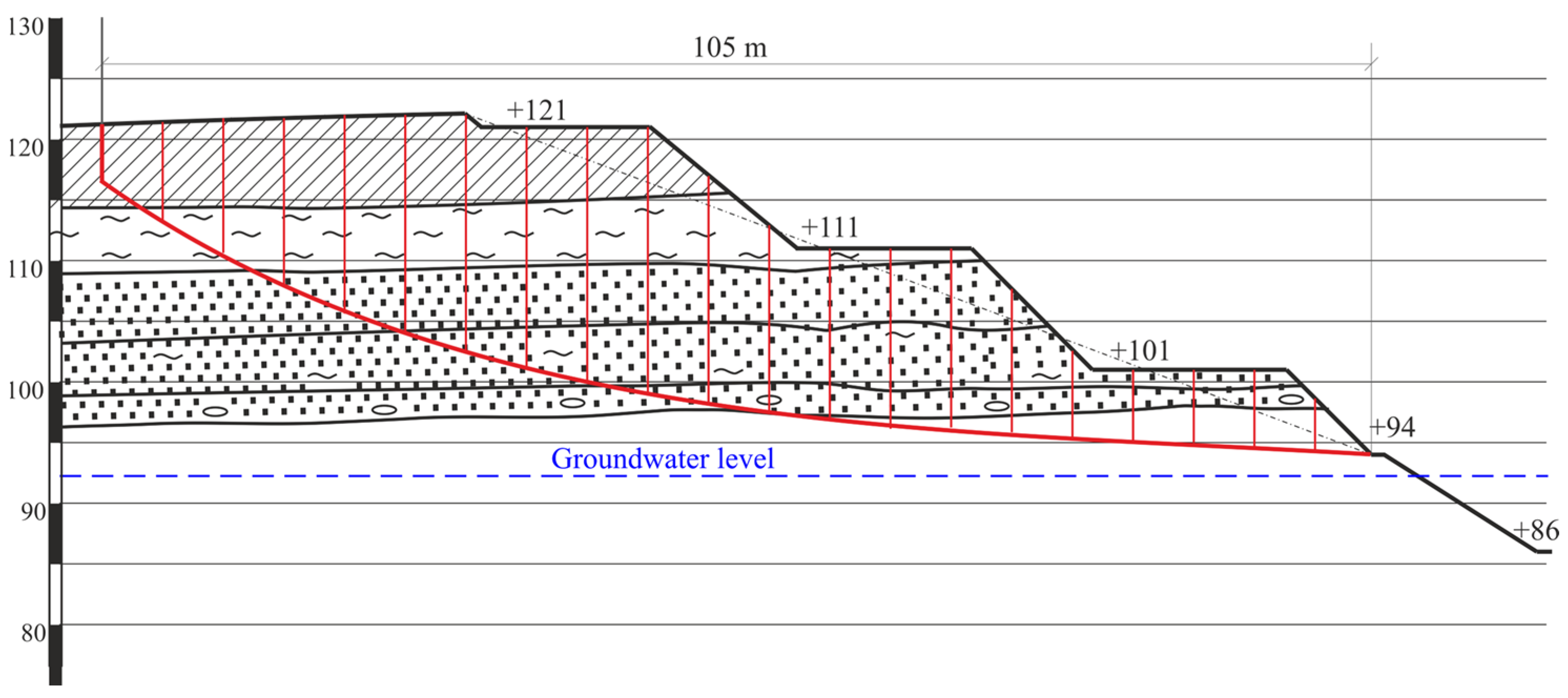
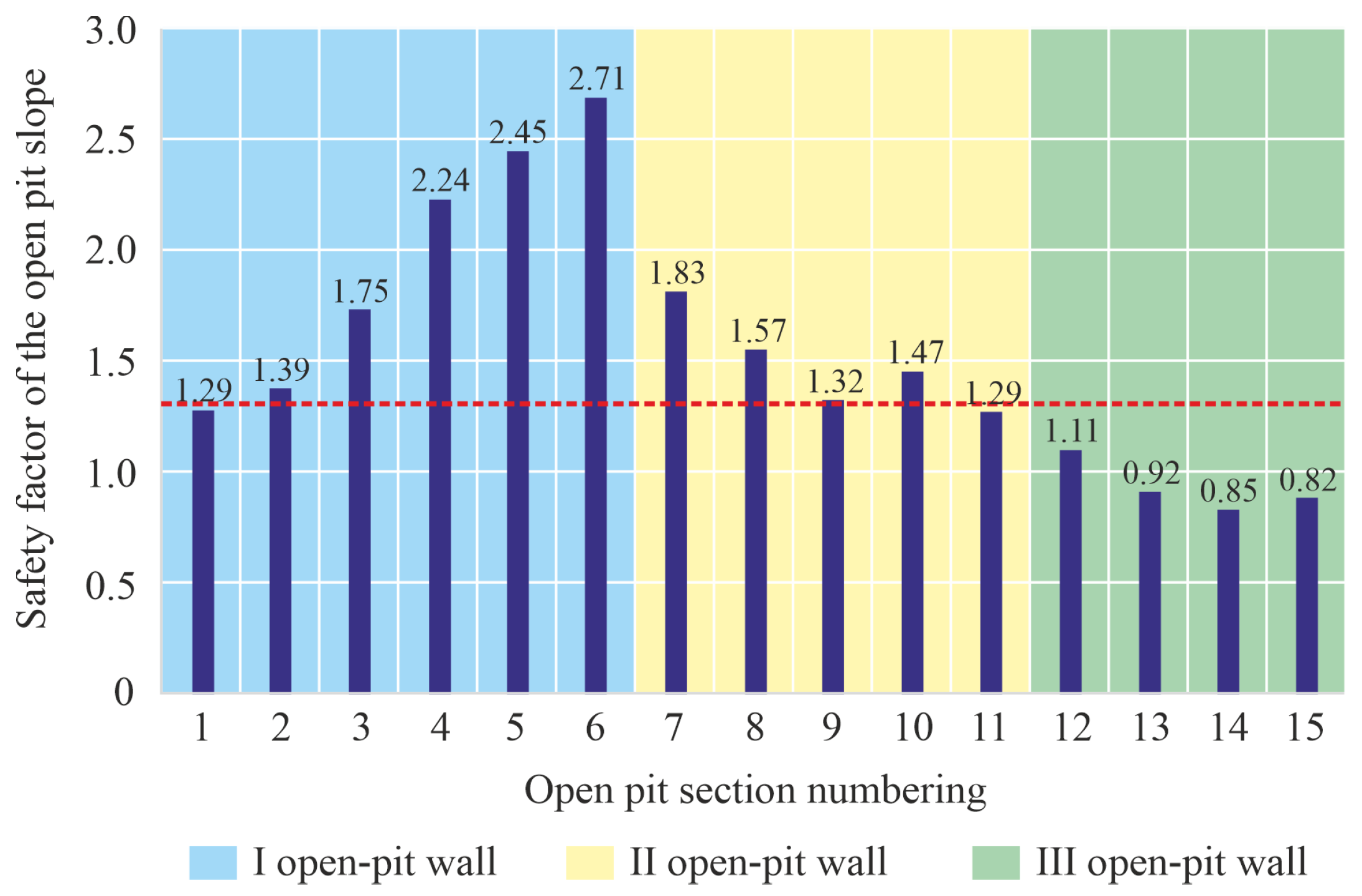
2.2. Determining the Safety Factor for the Open-Pit Walls

The choice of the direction for the development of mining operations is based on determining the stability index (n) for working wall and comparing it with the standard nн. According to current normative documents in Ukraine, the safety factor for open-pit walls with a lifespan of more than 10 years should be at least 1.3 [48].
The safety factor for open-pit walls can be determined by means of numerical modeling methods, using appropriate software, as well as graphical–analytical methods. In this paper, the above-mentioned parameters are determined using the method of algebraic addition of forces along a curvilinear shear surface. The safety factor for an open-pit wall, given the effects of hydrostatic pressure, is calculated by the following formula [49]:
n = ( b i × ( h i × γ i + P i × m i ) × cos α i Φ i ) × t g ρ i + c i × l i b i × ( h i × γ i + P i × m i ) × sin α i ,
where bi is the width of the calculated i-th block in the selected near-slope mass volume, m; hi is the height of the layer of dry and moistened rocks in the i-th block (in its middle), m; γi is specific weight in the i-th elementary column, t/m3; Pi is specific weight of watered rock, t/m3; mi is the width of the equipment supporting surface that loads the platform in the calculated i-th block, m; αi is the sliding plane slope angle within the i-th block, deg; ρi is internal friction angle in the i-th elementary column, deg; Φi is the force directed normal to the sliding plane at the midpoint of the i-th block, kN; ci is cohesion of the i-th layer, MPa; and li is the sliding plane length within the i-th block, m.
The combined influence of hydrostatic and hydrodynamic pressure is determined by the method of replacing volumetric forces with equivalent contour forces. Then, the resultant force is
Φ i = ( γ w × ( H i y i ) × a i cos α i ) ,
γw is the specific weight of water, t/m3; Hi is the average pressure within the i-th block, m; yi is the average ordinate of the sliding curve within the i-th block, m; ai is the i-th block width, m; and αi is the slope angle of the sliding plane in the middle of the i-th block base, deg. To determine the possible collapse prism parameters, namely, the sliding plane parameters (width, length) within the i-th block, the authors of the paper use a graphical method, including the construction of a calculation scheme for each studied open-pit wall area (Figure 3). AutoCAD software (23.1) is used to construct such a scheme.
The calculation scheme is constructed in several interrelated stages. In the first stage, based on the geological surveying service data, parameters characterizing the conditions of occurrence of rocks, their composition, and the change in thickness in the studied areas are depicted.
In the second stage, in the wall section constructed along the daylight surface, the width parameters of a possible collapse prism (a) from the upper edge (1) are indicated, which are determined by the following formula:
a = 2 H × [ 1 c t g α p × t g ( α p ρ a v 2 ) ] 2 H 90 t g ( 45 ° ρ a v 2 + t g ( α p + ρ a v 2 ) ) ,
where H is the wall height, m; and αp is the resultant wall slope angle, deg. This angle is measured from the lower to the upper edge. ρav is average internal friction angle, deg; and H90 is height of vertical outcrop, m. This value is determined by the following formula:
H 90 = 2 C c a v γ c a v × c t g ( 45 ° ρ a v 2 ) ,
where cav is average cohesion of interlayers in the studied area, t/m2. This value is determined by the following formula:
C a v = i = 1 k C i × l i i = 1 k l i = C 1 × l 1 + + C k × l k l 1 + + l k ,
t g ρ a v = i = 1 k t g ρ i × σ k × l i i = 1 k σ i × l i = t g ρ 1 × σ 1 × l 1 + + t g ρ k × σ k × l k σ 1 × l 1 + + σ k × l k ,
where σi is the normal stress value in the middle of the i-th sliding plane surface area, Pa. This value is determined by the following formula:
σ i = γ c p × h i × cos 2 α i ,
where γi is specific weight of the i-th interlayer, t/m3; and mi is thickness of the i-th interlayer, m.
γ a v = i = 1 k γ i × m i i = 1 k m i = γ 1 × m 1 + + γ k × m k m 1 + + m k ,
After indicating the prism (a) width, the vertical outcrop height (H90) is measured from point (2) of the daylight surface vertically. After that, the sliding plane line is constructed, which connects the vertical outcrop height (H90) at point 3 with the lower wall edge (point 4). Safety factor is determined for the south-western (I), western (II), and southern (III) open-pit walls, the length of which is as follows: I wall—326 m, II wall—285 m, III wall—250 m, respectively. The physical–mechanical properties of rocks forming the open-pit walls have both common and distinctive features. Therefore, the average safety factor is determined separately for each open-pit wall. This makes it possible to determine the safe distance parameters from the upper wall edge for placing mining equipment.

3. Results and Discussion

The analysis of the conducted research on the stability of the open-pit walls makes it possible to identify areas most prone to deformation processes, taking into account physical–mechanical peculiarities and hydrogeomechanical processes. To study the stability of the Pivdenno–Skhidnyi open pit walls, a total of 15 sections are constructed, on the basis of which the possible collapse prism parameters are investigated. There were six identified sections along the I wall with a distance between them of 65.2 m, five sections along the II wall with a distance between them of 57 m, and four sections along the III wall with a distance between them of 63.5 m. This quantity has been determined to be optimal. The analysis of the physical–mechanical properties of the rocks within the boundaries of the selected sections forming the open-pit walls indicates their common features. In general terms, the studied sections are shown in Figure 4, Figure 5 and Figure 6.
Based on the calculations performed using Formula (1), it has been revealed that the safety factor for the open-pit walls varies from 0.9 to 2.24, namely: I wall—from 1.29 to 2.71, II wall—from 1.29 to 1.83, and III wall—from 0.85 to 1.11. The general pattern of change in the stability index of the open-pit wall sections is shown in Figure 7.
The safety factor value for the III open-pit wall is lower than the standard one due to suffusion phenomena, which are formed and accompanied by the removal of finely dispersed particles from the sandy-clay stratum of Baltian sands and loams by the water flow.
As a result of this, the rock mass loosens under the influence of its mass, and the rocks located above are displaced. Due to their infiltration and the effects of groundwater, finely dispersed fine-grained sands are washed out in places where water seepage sources are visually observed. On the contacts of impermeable layers and interlayers of red-brown clays, potential sliding planes are formed, along which shear deformations occur. Shear deformations extend to the lower benches, composed of semi-hard and hard-crystalline rocks. Also, the specified process of removal by the water flow occurs at the boundary of the II and III walls, and this is confirmed by a decrease in the stability index to 1.29 (section 11). A similar situation is observed in the I open-pit wall (section 1). At the same time, an increase in the stability index within sections 3–8 is determined by the presence of coarser-grained Baltian sands saturated with pebbles, which significantly reduces suffusion processes and, accordingly, the possibility of shear processes. Based on the above, mining operations are prohibited within the boundaries of the III open-pit wall sections and I open-pit wall section. Given the position of the open-pit sections along the strike of its walls (I wall—326 m; II wall—285 m) and the determined width parameters of the possible collapse prism for each section (Table 2), the graph of a change in the prism width along the strike of the open-pit wall has been plotted. Accordingly, using the analysis of data in Figure 8, the change in the width parameters of the possible collapse prism can be determined at different points along the open-pit walls depending on the resultant open-pit wall slope (αp) and the vertical outcrop height (H90).
Based on the analysis of the calculation schemes for the studied sections of the open-pit walls, the possible collapse prism parameters can be determined (Table 2).
Analysis of the data given in Figure 8 indicates that the possible collapse prism width varies from 26.23 m to 32.54 m. In this case, provided that section I is taken as 0 m, mining equipment is allowed to be placed in the range of 41–598 m, which is the safe distance limit for its operation along the strike of the open-pit wall, the safety factor of which varies from 1.35 to 2.71. The reason for the decrease in the stability index within the boundaries of sections I (0–42 m) and 11 (598–611 m) is the collapse and shearing of semi-hard and hard rocks (weathered granitoid cherokites and kaolinized and mylonitized gneisses) due to the unfavorable occurrence of their layers on the contacts with fresh fractured migmatites and quartzites. Cherokites are represented by thin-banded granites and have a north-western strike of bedding surfaces (250–280°) and a subvertical dip (79–90°) to the northeast. In addition, the parameters of three fracture systems (strike azimuth of 252–282°, 280–300°, and 80–90°, as well as an incidence angle of 79–88°, 70–75°, and 2–7°) also contribute to the development of the specified deformations when the contact zones are outcropped by the bench slope.
Based on the conducted research, the following emphasis can be made on choosing the optimal direction for the development of mining operations:
  • The shear processes that occurred along the northern and north-eastern open-pit walls in sedimentary deposits are the consequence of the working front crossing the open pit along the strike of the main direction of movement (flows) of surface and groundwaters, which feeds the Southern Bug River.
  • The accepted western direction of the development of mining operations will not lead to significant shear processes in the western and north-western walls since the flow of surface and groundwaters is directed not into the open pit but into the Southern Bug River.
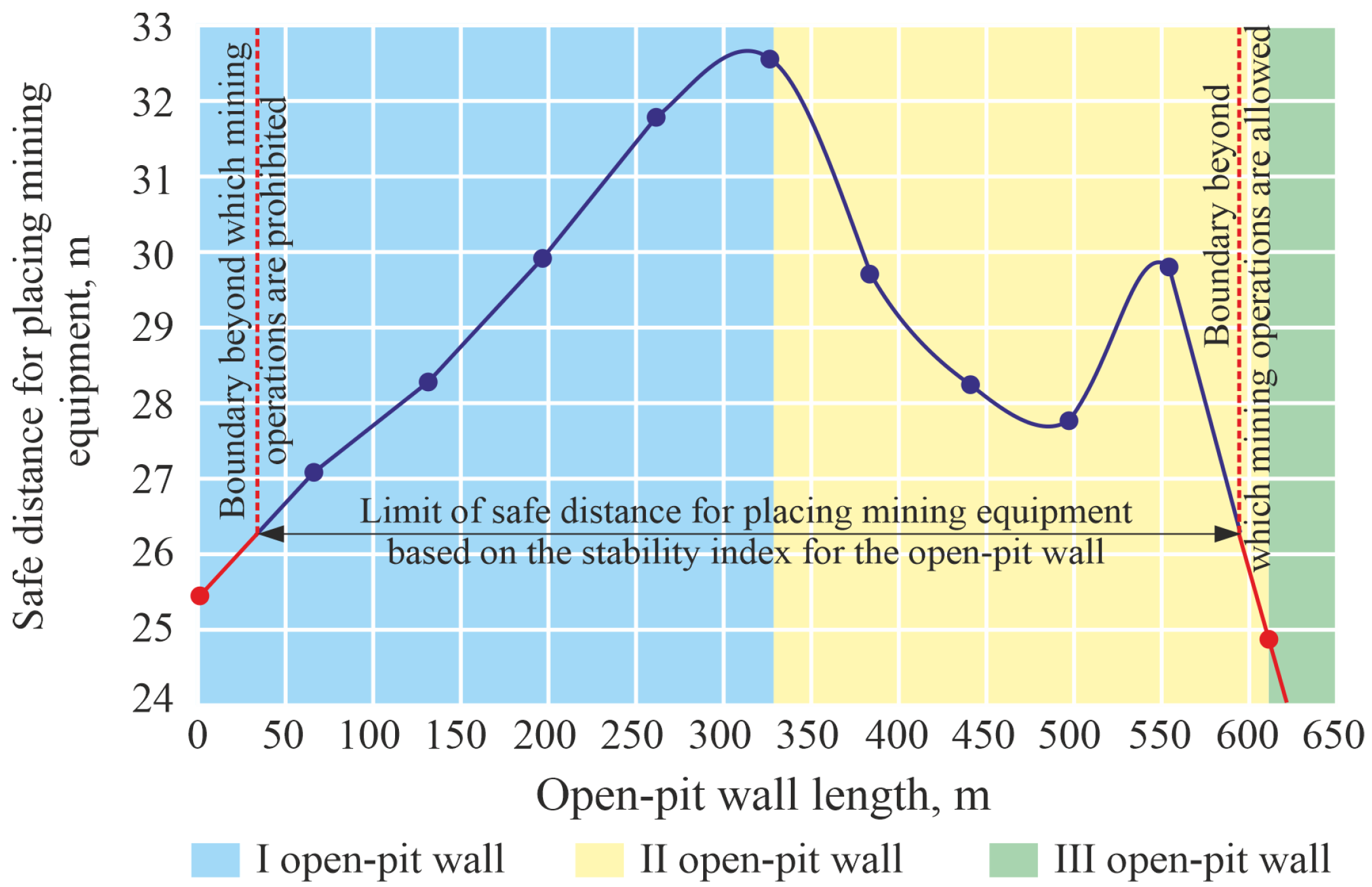
  • Mining operations will be conducted on the +86 m horizon, which is 7 m below the water level in the Southern Bug River. This area is located in the crystalline mass fractured zone. Therefore, when conducting mining operations, especially blasting ones, it is necessary to monitor the groundwater inflow from the crystalline mass from the side of the river. Since mining operations are performed according to the project, the barrier pillar is sufficient to ensure the safety of operations. It is proposed to consider the possibility of transitioning to drilling wells of smaller diameter. This will make it possible to reduce slips in the mass depth towards the river.
  • The adopted direction for the development of mining operations makes it possible to reduce the current stripping ratio, reduce the useful mineral transportation distance, and reactivate the southern open-pit wall.
  • Calculations of the wall stability in the open-pit areas within the thickness of soft rocks and weathered crystalline rocks have proven that its stable state is maintained at the following parameters of the benches and their slope angles:
-
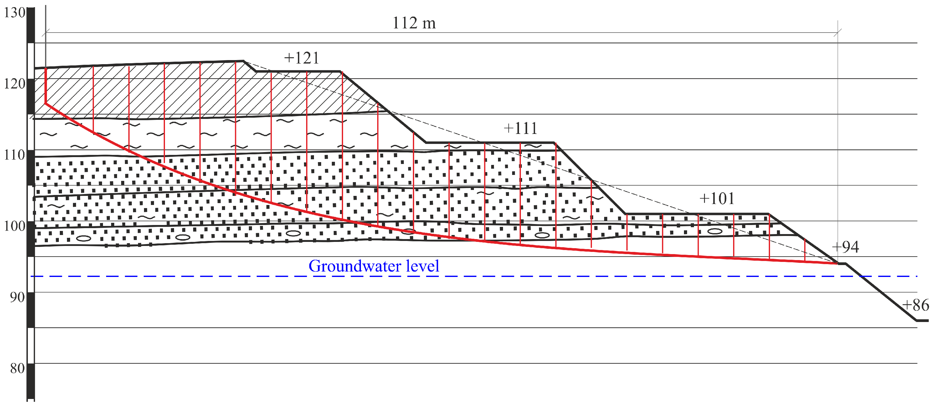
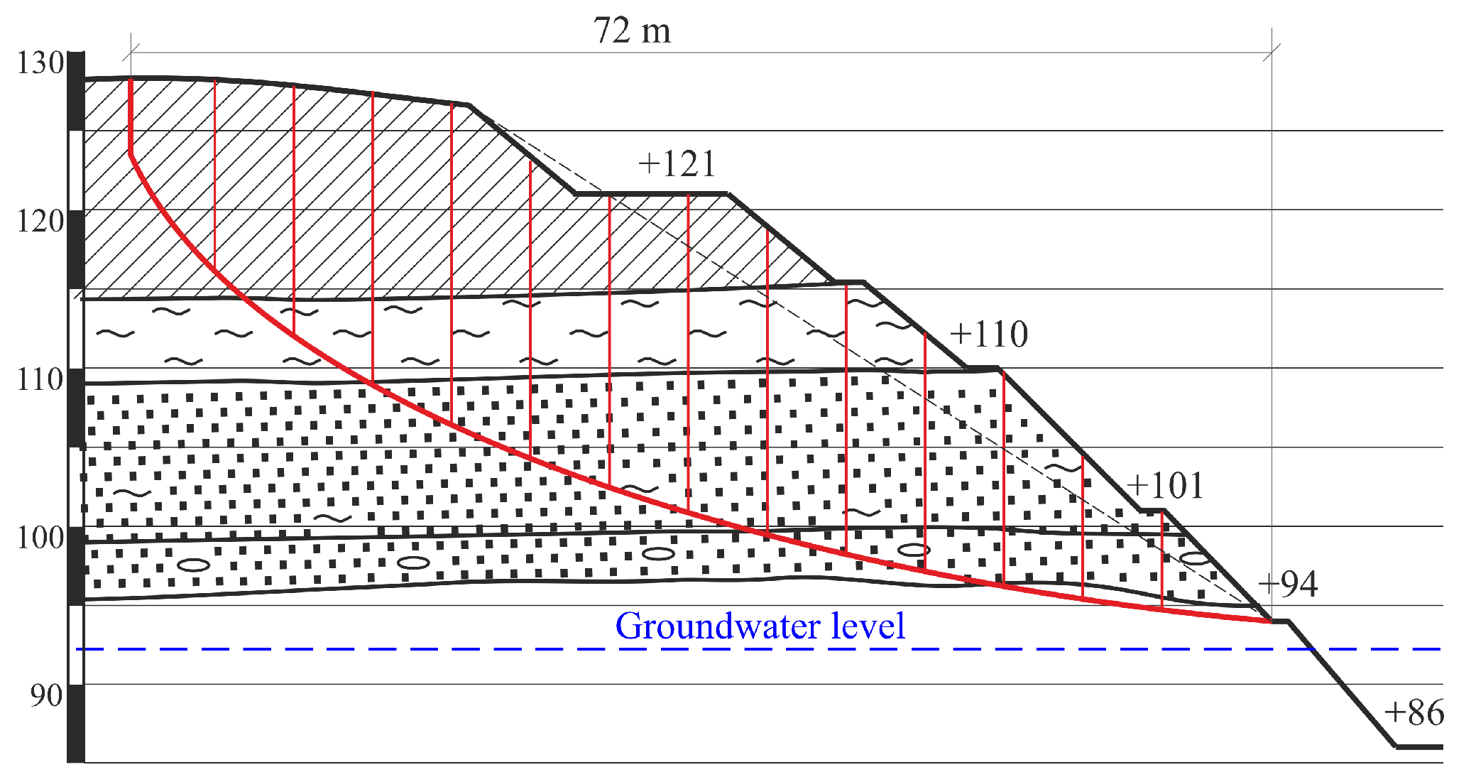
In the northern wall, mining is conducted in Precambrian rocks (weathered crystalline cherokites and gneisses), as well as in soft sediments. Bench slope angles are recommended as follows: loam—35°; red-brown clay—45°; sand—37°; light gray clays—25°; weathering crust rocks—45°; calciphyres—from 55° to 70°; other hard rocks—50–60°.
-
The height of benches in soft rocks and weathering crust should be 10 m, and in hard rocks, 15 m. The resultant slope angles of the walls have been found according to the specified recommendations: the thickness of soft rocks in the northern wall—20–26°, hard rocks—33.5–36.5°, and throughout the wall—30.5–35°. In the southern wall, similar slope angles are reached accordingly, 20–25° for soft rocks and 36.5–43° for hard rocks, and the resultant angle is 30.5–40°.
To ensure the long-term bench stability of water-cut Baltian sands and the wall as a whole in soft rock deposits, it is recommended to drain atmospheric water using a drainage shaft with a width of 1 m at the top and 5 m at the bottom.
In previously conducted studies for the mining conditions of the Zavalivskyi Graphite Deposit, the geomechanical stability of the open-pit walls was assessed, which makes it possible to direct the front of the advance of mining operations towards the I-III walls (the safety factor is ≥1.3) [50]. At the same time, when conducting mining operations on the open-pit walls, shear processes are constantly developing, caused by the action of hydrostatic pressure [51,52]. The research performed by the authors makes it possible for the first time to substantiate the direction of the development of open-pit mining operations for the conditions of the Zavalivskyi Graphite Deposit, taking into account the action of hydrostatic pressure.
Further research is expected to substantiate the parameters of safe mining technology when forming working sites and setting an effective transport link between the faces and the beneficiation complex.

4. Conclusions

It has been determined that the most promising direction for the development of mining operations in the Pivdenno–Skhidnyi open pit is its south-western, western, and north-eastern areas with a length of 556 m (I wall—42–326 m; II wall—326–598 m). The safety factor for the studied areas varies from 1.39 to 2.71. The impossibility of conducting mining operations within the boundaries of the III wall of the Pivdenno–Skhidnyi open pit (northern part) is conditioned by natural factors.
As a result of the conducted research, the dependence of change on the width of the possible collapse prism at various points along the open-pit walls has been obtained. This simplifies calculations when constructing a circular–cylindrical sliding line to further determine the open-pit wall safety factor. That is, this open-pit wall along its strike intersects three large gullies with a large hydraulic slope: eastern, central, and western. These gullies previously fed the Southern Bug River (before the creation of the open pit) and closed to the south of the existing open pit. The Southern Bug River was fed by surface water that flowed down the thalwegs of the gullies and by groundwater flowing from the Baltian sands. Thus, in the process of mining operations, the rocks of the III open-pit wall outcrop the movement zones (flows) of the surface and groundwaters, which leads to sudden shear processes and loss of the wall stability index. Therefore, within the III wall boundaries of the Pivdenno–Skhidnyi open pit, it is strictly forbidden to conduct mining operations.
At the same time, the analysis of the promising direction for the development of mining operations indicates that mining operations will be conducted on the +86 m horizon, which is 7 m below the water level in the Southern Bug River. This area is located in the crystalline mass fractured zone. Therefore, when conducting mining operations, especially blasting ones, it is necessary to monitor the groundwater inflow from the crystalline mass from the side of the river. Further research is planned to conduct a study on the substantiation of the barrier pillar parameters to ensure the safety of operations. Moreover, it is additionally planned to consider the possibility of changing the diameter of the blast holes, thereby reducing slips in the mass depth towards the river.

Author Contributions

Conceptualization, P.S. and O.C.; methodology, O.C.; software, O.C. and O.A; validation, P.S., O.A. and K.R.; formal analysis, O.A.; investigation, O.C.; resources, K.R.; data curation, P.S.; writing—original draft preparation, P.S. and O.C.; writing—review and editing, O.C. and K.R.; visualization, P.S.; supervision, P.S. and K.R.; project administration, O.C. and O.A.; funding acquisition, P.S. and K.R. All authors have read and agreed to the published version of the manuscript.

Funding

This study was carried out as part of the project “Belt and Road Initiative Centre for Chinese-European studies (BRICES)” and was funded by the Guangdong University of Petrochemical Technology.

Institutional Review Board Statement

Not applicable.

Informed Consent Statement

Not applicable.

Data Availability Statement

All data generated or analyzed during this study are included in this published article.

Acknowledgments

This study is supported by the National Research Foundation of Ukraine (project No. 2022.01/0107, “A resource-saving technology development for mining and processing of non-metallic mineral raw materials in the war and post-war periods” for the call “Science for the Recovery of Ukraine in the War and Post-War Periods”).

Conflicts of Interest

The authors declare no conflict of interest.

References

  1. Parka, J.-S.; Myung, S.-T. Development of Secondary Battery Market and Trends of Solid-State Batteries. J. Korean Batter. Soc. 2022, 2, 62–66. [Google Scholar] [CrossRef]
  2. Jeppe, A.; Proff, H.; Eickhoff, M. Economic Potentials of Ecologically Attractive Multi-Life Products—The Example of Lithium-Ion Batteries. Sustainability 2023, 15, 11184. [Google Scholar] [CrossRef]
  3. Novotny, A.; Szeberin, I.; Kovács, S.; Máté, D. National Culture and the Market Development of Battery Electric Vehicles in 21 Countries. Energies 2022, 15, 1539. [Google Scholar] [CrossRef]
  4. Liu, B.; Song, C.; Liang, X.; Lai, M.; Yu, Z.; Ji, J. Regional differences in China’s electric vehicle sales forecasting: Under supply-demand policy scenarios. Energy Policy 2023, 177, 113554. [Google Scholar] [CrossRef]
  5. Khatua, A.; Kumar, R.R.; De, S.K. Institutional enablers of electric vehicle market: Evidence from 30 countries. Transp. Res. Part A Policy Pr. 2023, 170, 103612. [Google Scholar] [CrossRef]
  6. Sanguesa, J.A.; Torres-Sanz, V.; Garrido, P.; Martinez, F.J.; Marquez-Barja, J.M. A Review on Electric Vehicles: Technologies and Challenges. Smart Cities 2021, 4, 372–404. [Google Scholar] [CrossRef]
  7. Agusdinata, D.B.; Liu, W. Global sustainability of electric vehicles minerals: A critical review of news media. Extr. Ind. Soc. 2023, 13, 101231. [Google Scholar] [CrossRef]
  8. Yang, A.; Liu, C.; Yang, D.; Lu, C. Electric vehicle adoption in a mature market: A case study of Norway. J. Transp. Geogr. 2023, 106, 103489. [Google Scholar] [CrossRef]
  9. Hoen, F.S.; Díez-Gutiérrez, M.; Babri, S.; Hess, S.; Tørset, T. Charging electric vehicles on long trips and the willingness to pay to reduce waiting for charging. Stated preference survey in Norway. Transp. Res. Part A Policy Pr. 2023, 175, 103774. [Google Scholar] [CrossRef]
  10. Xu, C.; Behrens, P.; Gasper, P.; Smith, K.; Hu, M.; Tukker, A.; Steubing, B. Electric vehicle batteries alone could satisfy short-term grid storage demand by as early as 2030. Nat. Commun. 2023, 14, 119. [Google Scholar] [CrossRef]
  11. Meegoda, J.N.; Malladi, S.; Zayas, I.C. End-of-Life Management of Electric Vehicle Lithium-Ion Batteries in the United States. Clean Technol. 2022, 4, 1162–1174. [Google Scholar] [CrossRef]
  12. Sun, D.; Kyere, F.; Sampene, A.K.; Asante, D.; Kumah, N.Y.G. An investigation on the role of electric vehicles in alleviating environmental pollution: Evidence from five leading economies. Environ. Sci. Pollut. Res. 2023, 30, 18244–18259. [Google Scholar] [CrossRef] [PubMed]
  13. Hossain, M.S.; Kumar, L.; Assad, M.E.H.; Alayi, R. Advancements and Future Prospects of Electric Vehicle Technologies: A Comprehensive Review. Complexity 2022, 2022, 3304796. [Google Scholar] [CrossRef]
  14. Yuan, S.; Lai, Q.; Duan, X.; Wang, Q. Carbon-based materials as anode materials for lithium-ion batteries and lithium-ion capacitors: A review. J. Energy Storage 2023, 61, 106716. [Google Scholar] [CrossRef]
  15. Li, M.; Kanazhanov, A.; Shalbayev, K. Rechargeable batteries. Solid state electric vehicle batteries. Eng. J. Satbayev Univ. 2021, 143, 285–289. [Google Scholar] [CrossRef]
  16. Mezaal, M.A.; Qu, L.; Li, G.; Liu, W.; Zhao, X.; Zhang, K.; Zhang, R.; Lei, L. LiMO2@Li2MnO3 positive-electrode material for high energy density lithium ion batteries. J. Solid State Electrochem. 2016, 21, 145–152. [Google Scholar] [CrossRef]
  17. Zhu, G.; Liang, P.; Huang, C.L.; Huang, C.C.; Li, Y.Y.; Wu, S.C.; Li, J.; Wang, F.; Tian, X.; Huang, W.H.; et al. High-Capacity Rechargeable Li/Cl2 Batteries with Graphite Positive Electrodes. J. Am. Chem. Soc. 2022, 144, 22505–22513. [Google Scholar] [CrossRef]
  18. Kropivnyy, V.; Molokost, L.; Kuzyk, O.; Kropivnaya, A. Comparative Industrial Assessment of Graphite Deposits and Ores of Ukraine, Characteristics of Ore Concentration. Central Ukrainian Scientific Bulletin. Tech. Sci. 2019, 1, 93–102. [Google Scholar] [CrossRef]
  19. Shpylovyi, L.; Biletskyi, V. Ukrainian graphite. Geotechnologies 2020, 3, 14–25. [Google Scholar]
  20. Yatsenko, V.G.; Zaborovska, L.P.; Zemskov, G.O.; Lyzhachenko, N.M.; Nikolaevskiy, V.P. Rational using of raw materials during exploitation of the Zavalievsky graphite deposit. Geochem. Technog. 2020, 31, 5–15. [Google Scholar] [CrossRef]
  21. Kravtsova, I.V.; Sytnyk, O.I.; Nikolaievskyi, V.P.; Denysyk, B.G. Anthropogenic transformation of the physical surface of the Hayvoron region on the example of the Zavalivsk graphite deposit. In Proceedings of the 16th International Conference Monitoring of Geological Processes and Ecological Condition of the Environment, Kyiv, Ukraine, 15–18 November 2022; pp. 1–5. [Google Scholar] [CrossRef]
  22. Kulikov, P.; Aziukovskyi, O.; Vahonova, O.; Bondar, O.; Akimova, L.; Akimov, O. Post-war Economy of Ukraine: Innovation and Investment Development Project. Econ. Aff. 2022, 67, 943–959. [Google Scholar] [CrossRef]
  23. Novak, A.; Pravdyvets, O.; Chornyi, O.; Sumbaieva, L.; Akimova, L.; Akimov, O. Financial and Economic Security in the Field of Financial Markets at the Stage of European Integration. Int. J. Prof. Bus. Rev. 2022, 7, e0835. [Google Scholar] [CrossRef]
  24. Boubazine, L.; Boumazbeur, A.; Hadji, R.; Fares, K. Slope failure characterization: A joint multi-geophysical and geotechnical analysis, case study of Babor Mountains range, NE Algeria. Min. Miner. Depos. 2022, 16, 65–70. [Google Scholar] [CrossRef]
  25. Anisimov, O.; Symonenko, V.; Cherniaiev, O.; Shustov, O. Formation of safety conditions for development of deposits by open mining. E3S Web Conf. 2018, 60, 00016. [Google Scholar] [CrossRef]
  26. Lozhnikov, O.; Shustov, O.; Chebanov, M.; Perkova, T. Methodological principles of the selection of a resource-saving technology while developing water-bearing placer deposits. Min. Miner. Depos. 2022, 16, 115–122. [Google Scholar] [CrossRef]
  27. Baibatsha, A.B.; Bekbotayeva, A.A.; Bekbotayev, A.T. Ore minerals of Carboniferous copper sediment-hosted Zhezkazgan deposit (Central Kazakhstan). Surv. Geol. Min. Ecol. Manag. SGEM 2015, 1, 329–335. [Google Scholar]
  28. Sdvyzhkova, O.; Moldabayev, S.; Bascetin, A.; Babets, D.; Kuldeyev, E.; Sultanbekova, Z.; Amankulov, M.; Issakov, B. Probabilistic assessment of slope stability at ore mining with steep layers in deep open pits. Min. Miner. Depos. 2022, 16, 11–18. [Google Scholar] [CrossRef]
  29. Gorova, A.; Pavlychenko, A.; Borysovs’Ka, O. The study of ecological state of waste disposal areas of energy and mining companies. In Annual Scientific-Technical Colletion—Mining of Mineral Deposits; CRC Press: Boca Raton, FL, USA, 2013; pp. 169–172. [Google Scholar] [CrossRef]
  30. Strilets, O.; Pcholkin, G.; Oliferuk, V. Monitoring of mass blasting seismic impact on residencial buildings and con-structions. In New Developments in Mining Engineering; CRC Press: Boca Raton, FL, USA, 2015; pp. 533–535. [Google Scholar]
  31. Saptono, S.; Rezky, D.M. Sensitivity analysis of nickel haul road embankment slopes using the coefficient of variation approach. Min. Miner. Depos. 2022, 16, 48–53. [Google Scholar] [CrossRef]
  32. Symonenko, V.; Cherniaiev, O.; Hrytsenko, L. Organization of non-metallic deposits development by steep excava-tion layers. Min. Miner. Depos. 2016, 10, 68–73. [Google Scholar] [CrossRef]
  33. Chernyaev, O.V. Systematization of the hard rock non-metallic mineral deposits for improvement of their mining technologies. Sci. Bull. Natl. Min. Univ. 2017, 5, 11–18. [Google Scholar]
  34. Shirin, L.N.; Denishchenko, A.V.; Yurchenko, O.O.; Mikhalev, D.V. Methodology for determination of rope vehicles energy consumption. Nauk. Visnyk Natsionalnoho Hirnychoho Universytetu 2012, 4, 464–469. [Google Scholar]
  35. Huang, F.; Luo, X.; Liu, W. Stability Analysis of Hydrodynamic Pressure Landslides with Different Permeability Coefficients Affected by Reservoir Water Level Fluctuations and Rainstorms. Water 2017, 9, 450. [Google Scholar] [CrossRef]
  36. Zerradi, Y.; Souissi, M.; Larabi, A. Application of the deterministic block theory to the slope stability design of an open-pit mine in Morocco. Min. Miner. Depos. 2023, 17, 53–60. [Google Scholar] [CrossRef]
  37. Pavlychenko, A.; Kovalenko, A. The investigation of rock dumps influence to the levels of heavy metals contami-nation of soil. In Annual Scientific-Technical Collection—Mining of Mineral Deposits; CRC Press: Boca Raton, FL, USA, 2013; pp. 237–238. [Google Scholar] [CrossRef]
  38. Gumenik, I.L.; Lozhnikov, O.V.; Panasenko, A.I. Deliberate dumping technology for mining reclamation effectiveness improvement. Sci. Bull. Natl. Min. Univ. 2013, 5, 48–53. [Google Scholar]
  39. Petlovanyi, M.; Sai, K.; Khalymendyk, O.; Borysovska, O.; Sherstiuk, Y. Analytical research of the parameters and characteristics of new “quarry cavities—backfill material” systems: Case study of Ukraine. Min. Miner. Depos. 2023, 17, 126–139. [Google Scholar] [CrossRef]
  40. Saik, P.B.; Dychkovskyi, R.O.; Lozynskyi, V.G.; Malanchuk, Z.R.; Malanchuk, Y.Z. Revisiting the Underground Gasification of Coal Reserves from Contiguous Seams. Nauk. Visnyk Natsionalnoho Hirnychoho Universytetu 2016, 6, 60–66. [Google Scholar]
  41. Lozynskyi, V. Critical review of methods for intensifying the gas generation process in the reaction channel during underground coal gasification (UCG). Min. Miner. Depos. 2023, 17, 67–85. [Google Scholar] [CrossRef]
  42. Chetverik, M.S.; Bubnova, E.A. Zaklyuchenie o prichinah obrazovaniya opolznya (sdvizhenie massiva gornyih porod) na Chkalovskom karere OAO «OGOK». Geo-Tech. Mech. 2007, 45, 18–28. [Google Scholar]
  43. Chetveryk, M.; Bubnova, O.; Babiy, K. The rate of deformation development in the rock massif on the basis of surveying monitoring on the earth surface. Min. Miner. Depos. 2017, 11, 57–74. [Google Scholar] [CrossRef]
  44. Elbeblawi, M.M.A.; Elsaghier, H.A.A.; Amin, M.T.M.; Abdellah, W.R.E. Surface Mining Technology; Springer Science and Business Media LLC: Dordrecht, GX, Netherlands, 2022; ISBN 9780412607608. [Google Scholar]
  45. Bazaluk, O.; Anisimov, O.; Saik, P.; Lozynskyi, V.; Akimov, O.; Hrytsenko, L. Determining the Safe Distance for Mining Equipment Operation When Forming an Internal Dump in a Deep Open Pit. Sustainability 2023, 15, 5912. [Google Scholar] [CrossRef]
  46. Petlovanyi, M.; Malashkevych, D.; Sai, K.; Zubko, S. Research into balance of rocks and underground cavities formation in the coal mine flowsheet when mining thin seams. Min. Miner. Depos. 2020, 14, 66–81. [Google Scholar] [CrossRef]
  47. Bazaluk, O.; Sadovenko, I.; Zahrytsenko, A.; Saik, P.; Lozynskyi, V.; Dychkovskyi, R. Forecasting Underground Water Dynamics within the Technogenic Environment of a Mine Field. Case Study. Sustainability 2021, 13, 7161. [Google Scholar] [CrossRef]
  48. SOU-N MPP 73.020-078-1:2007; Standards for Technological Design of Mining Enterprises with Open-Pit Mining. Part 1. Mining Operations. Liquidation of Mining Enterprises. Technical-Economic Assessment and Indicators. Directive of the Ministry of In-dustrial Policy of Ukraine. Ministry of Industrial Policy of Ukraine: Kyiv, Ukraine, 2007.
  49. Shapar, A.G.; Kopach, P.I.; Romanenko, V.N.; Yakubenko, L.V.; Nesmashniy, E.; NIkolashin, Y.M.; Shevchenko, D.O. Metodichni/I Vkazivki z Viznachennya Optimalnih kutiv Nahilu Bortiv, Ukosiv Ustupiv i Vidvaliv Zalizorudnih ta Flyusovih Kar’Eriv; Kryvyi Rih National University: Kryvyi Rih, Ukraine, 2009; p. 2001. [Google Scholar]
  50. Starshov, V.F. Korrektirovka proekta rekonstruktsii s tselyu podderzhaniya deystvuyuschih moschnostey Zavalevskogo grafitovogo kombinata. In Project of Gipronimetallorud; National Mining University of Ukraine: Dnipro, Ukraine, 2009; p. 450. [Google Scholar]
  51. Symonenko, V.I.; Pavlychenko, A.V.; Anisimov, O.O.; Bondarenko, A.O.; Cherniaiev, O.V.; Hrytsenko, L.S. Tekhnolohiia Ekolohobezpechnoi Vidkrytoi Rozrobky Nerudnykh Rodovyshch Tverdykh Korysnykh Kopalyn; Zhurfond: Dnipro, Ukraine, 2022; p. 365. [Google Scholar]
  52. Malieiev, Y.V. Modern methods of reclamation of disturbed land landscape in terms of open-pit mining of horizontal deposits. Heotekhnichna Mekhanika 2017, 132, 130–137. [Google Scholar]
Figure 1. The trend toward increasing sales of electric vehicles.
Sustainability 15 15690 g001
Figure 2. Location of the site under study and screenshots from Google Earth (map of Ukraine was adapted using [46,47]).
Sustainability 15 15690 g002
Figure 3. Schemes follow the same formatting.
Sustainability 15 15690 g003
Figure 4. Calculation scheme for substantiating the I wall stability of the Pivdenno–Skhidnyi open pit.
Sustainability 15 15690 g004
Figure 5. Calculation scheme for substantiating the II wall stability of the Pivdenno–Skhidnyi open pit.
Sustainability 15 15690 g005
Figure 6. Calculation scheme for substantiating the III wall stability of the Pivdenno–Skhidnyi open pit.
Sustainability 15 15690 g006
Figure 7. Safety factor for the studied open-pit wall sections (red dashed line is normative safety factor).
Sustainability 15 15690 g007
Figure 8. Dependence of change on the safe distance for placing mining equipment (dragline) along the strike of the open-pit walls.
Sustainability 15 15690 g008
Table 1. Physical–mechanical properties of the Zavalivskyi Graphite Deposit rocks.
Rock TypeSpecific Weight,
γ, t/m3
Cohesion,
C × 10−2 MPa
Internal Friction Angle,
φ, Deg.
Porosity,
n, %
Moisture Content,
W, %
Filtration
Factor,
Kf, m/day
Structure Weakening Coefficient, λ0
Brownish-yellow loam, thickness is 3–6 m1.932.6019.45117.2–18.80.120.8
Dark brown loam, thickness is 7–8 m1.913.7119.14124–250.010.8
Red-brown clay, thickness is 13–18 m2.036.8518.04019–220.0010.7
Sand, thickness is 1–10 m1.69029.34010–161.0–6.00.2–0.8
Light gray clay, thickness is 5–8 m2.028.4617.346–4920–300.0050.6
Light gray water-saturated clay2.051.9914.232–4332–350.010.6
Weathering crust of crystalline rocks, weathered kaolinite gneissic1.9–2.15.70–76.619–313–250.7–180.01–0.050.1–0.6
Granites, gneisses1.9–2.9592–375020–360.3–4.20.07–0.50.03–0.09
Brownish-yellow loam, thickness is 3–6 m1.932.6019.45117.2–18.80.120.8
Dark brown loam, thickness is 7–8 m1.913.7119.14124–250.010.8
Red-brown clay, thickness is 13–18 m2.036.8518.04019–220.0010.7
Table 2. The possible collapse prism parameters in the studied sections.
Studied
Section No.
Height of Vertical Outcrop, H90, mWidth of a Possible Collapse Prism, a, mResultant Wall Angle, αp, Degi-th Block No. and the Sliding Plane Length within Its Boundaries, li, mCalculated i-th Block Width in the Selected Near-Slope Mass Volume, bi, mHeight of the Layer of Dry and Moistened Rocks in the i-th Block, hi, m
I wall15.8225.4827.51 = 4.85
2–19 = 5.0
20 = 1.89
1.73–23.472.47–5.92
25.3527.1225.61 = 4.92
1–19 = 5.0
20 = 2.49
1.98–23.173.17–6.17
34.9128.3122.51 = 5.37
2–19 = 5.0
20 = 2.71
2.39–22.743.42–6.31
44.6329.9220.61–20 = 5.0
21 = 2.6
2.42–21.514.67–6.05
54.2331.7819.31 = 5.57
2–20 = 5.0
21 = 1.89
2.92–23.172.12–6.71
63.9732.5418.21 = 5.79
2–20 = 5.0
21 = 2.71
4.19–22.913.21–6.92
II wall74.5429.7123.51 = 5.51
2–20 = 5.0
21 = 4.75
2.61–22.124.62–6.61
84.7128.2721.71 = 4.91
2–21 = 5.0
22 = 1.72
1.69–21.722.39–6.51
95.0127.7918.81 = 6.68
2–21 = 5.0
22 = 2.34
1.72–20.334.62–7.84
104.7229.8123.71 = 4.71
2–20 = 5.0
21 = 1.79
2.97–21.153.89–6.27
115.8724.9126.91 = 4.23
2–18 = 5.0
19 = 2.15
3.01–23.734.35–6.07
III wall126.5923.1228.41 = 6.34
2–13 = 5.0
14 = 2.71
3.08–21.035.47–8.75
137.7821.3832.71 = 5.33
2–12 = 5.0
13 = 3.52
3.44–20.216.99–9.14
148.1220.5437.51 = 4.75
2–11 = 5.0
12 = 3.12
4.21–21.786.71–8.91
158.5919.7131.81 = 4.13
2–10 = 5.0
13 = 2.71
2.17–22.715.31–8.75
Disclaimer/Publisher’s Note: The statements, opinions and data contained in all publications are solely those of the individual author(s) and contributor(s) and not of MDPI and/or the editor(s). MDPI and/or the editor(s) disclaim responsibility for any injury to people or property resulting from any ideas, methods, instructions or products referred to in the content.

