Article

Improvement of Fault Ride-Through Capability of Grid Connected Wind Turbine Based on a Switched Reluctance Generator Using a Dynamic Voltage Restorer

by
Saeed A. AlGhamdi
Electrical Engineering Department, Faculty of Engineering, Al-Baha University, Al-Baha 65528, Saudi Arabia
Sustainability 2023, 15(14), 11061; https://doi.org/10.3390/su151411061
Submission received: 20 May 2023 / Revised: 9 July 2023 / Accepted: 12 July 2023 / Published: 14 July 2023
(This article belongs to the Section Energy Sustainability)

Abstract

:
This paper presents an improvement to the fault ride-through (FRT) capabilities for a wind turbine that employs a switched reluctance generator (SRG) using a dynamic voltage restorer (DVR). The wind turbine may be disconnected from the grid by voltage sag, swell, and faulty line voltage in the grid. To improve the stator voltage of an SRG during grid failures, the DVR is applied to inject voltage at the point of common coupling (PCC) into the grid voltage. A control strategy for the DVR based on fuzzy logic controller (FLC) is proposed in this study to improve the FRT capability and meet the grid codes while avoiding the disconnection of the turbine from the grid. MATLAB/SIMULINK simulation validated the effectiveness and performance of this approach under three test cases: balanced sag, unbalanced sag, and a single line-to-ground fault. In addition, the total harmonic distortions utilizing different controllers were compared in sag mode. Furthermore, the simulation results exhibited significant improvement in transient and steady-state response, thus verifying the effectiveness of the control strategy compared to traditional methods.

1. Introduction

The most important sort of renewable energy technology is wind power; therefore, scientists have started substantial research on this area to discover more practical and dependable techniques [1]. The grid may be greatly impacted by the rising penetration of wind energy, particularly conditions for low-voltage ride-through (LVRT). Moreover, in several regions, the power grid connection codes need a wind turbine (WT) to take part in steady-state grid-voltage support and stay coupled to the grid in the meantime and to keep their reliability after a short-time fault [2]. One of the more recent grid standards for wind energy is the (LVRT) capability, which allows the grid to be provided with reactive currents under transient conditions (e.g., the China GB/T 19963 [2], the Federal Energy Regulatory Commission (FERC) [2,3]).
Due to its high-power density, mechanical robustness, high fault tolerance, cheap production costs, performance at a wide range of speeds, and great efficiency, a switched reluctance generator (SRG) is studied for WT systems [4,5]. Based on SRG performance as the wind speed varies, this generator can be a suitable replacement and run more efficiently [5]. Nevertheless, since the stator is connected via the converter to the grid, SRG is highly susceptible to grid faults such as current and voltage distortion in the stator winding, which could damage the stator converter or endanger SRG normal operation. After recovery, the WT must be disconnected and reconnected automatically from and to the grid to avoid the above-mentioned problems and protect the converter.
Once the voltage falls to a specific range at the point of common coupling (PCC) because of power system failures or disturbances, LVRT WT can operate continuously while holding its grid connection [3]. The WT’s LVRT capability ensures a balanced power system and maintains a stable frequency during and after disturbances. If WTs are not equipped with LVRT capability, if a fault subsists on the grid, WTs may trip [6]. Figure 1 demonstrates the necessities for LVRT in the United States. The WTGs should guarantee unremitting working without disconnection for 0.625 s when the PCC voltage drops to 15% of the rated voltage. When the PCC voltage recovers up to 90% of its rated voltage within 3 s following a voltage drop, generators should be able to provide continuous service without disconnection [3].
FERC Order No. 661A modified the LVRT requirement, allowing WTs (behind the transitional period) to “ride through low-voltage events fall to (0) voltage level for ‘location specific’ times of clearing up to the highest of 9 cycles” [3].
The LVRT grid codes can be met using an extensive variety of devices. To increase LVRT capability, series devices such as the dynamic voltage restorer (DVR), the thyristor-controlled voltage regulator (TCVR) in a position to inject series voltage, and super-conducting fault-current limiters (SFCL) have the intended results [7,8]. Additionally, it is not cost-effective to increase this capacity using a shunt device similar the static synchronous compensator (STATCOM) [9]. Conferring to the network code curves in Figure 1, the recovery time is clearly within acceptable recovery limits.
A shunt compensation like STATCOM coupled with the PCC.STATCOM reduces clearing time for faults and provides increased decelerating torque for the generator once the voltage is restored. This results in a growth in the generator’s stability boundary but also increases the mechanical stress [10,11]. Since no additional protection circuit is required for operation, a DVR is a good solution [12].
A control technique for the enhancement of LVRT capabilities of a grid-linked wind turbine based on SRG was put forth in the literature [13]. The proportional integral (PI) controllers worked well for controlling the power circuits. Going on the rule of the Widrow–Hoff delta, the adaptation algorithm is constructed. Research has confirmed that the performance of the fault ride-through (FRT) in wind turbines can be significantly improved through controller design. In a study by the authors in [11], a DVR with combined feed-forward and feed-Back (CFFFB) control was utilized to regulate voltage using a PI controller. The voltage controller generates switching pulses of voltage source inverter (VSI) in the CFFFB scheme using the output voltage sensed by the DVR (or load voltage). The performance of the solution to repair most grid faults is determined by the control procedure employed in the DVR for the FRT competence in SRG. In several steps, DVR control is accomplished, including finding reference generation, modulation and voltage-current control [14]. The PI control technique is simple to understand and straightforward to use. Due to its fixed gains, it is also inappropriate for systems with varying operating conditions and parameters. [15].
A.D. Falehi et al. [16] introduced a novel multi-level inverter (MLI) to give a staircase sinusoidal voltage of high-level numbers and fewer switches than with the other MLIs. The held-forth MLI may work as an “Odd-nary” cascaded asymmetric-type MLI (OCAMLI) by adding capacitors of the sub-MLI, bi-directional switches, and DC sources. The enactment of the recommended DVR-OCAMLI has been checked with shallow and deep unbalanced and balanced voltage sags. The performance and accuracy of the DVR-OCAMLIs have been compared with the classical DVR. Analytical study and simulation results have corroborated the OCAMLI performance in comparison with the other MLIs. The DVR-OCAMLI has compensated shallow and deep asymmetric and symmetric voltage sags for enhancing the LVRT capability.
An innovative asymmetrical mutual E-type clamped X-type MLI was proposed by Ali D. Falehi et al. [17] for the provision of a high-step staircase sinusoidal-type voltage with a minimal number of switches. For super capacitor-based power supplies, a new, durable super-twisting sliding-type control of fractional order is introduced. This control produces a smooth and steady DC voltage. To demonstrate its capacity for step production, it was compared to recently proposed and traditional inverters. The newly added controller improved the system’s resistance to uncertainties, freedom, and nonlinearities. Smooth and steady DC voltage can be delivered. The suggested scheme has been associated with SMC, FLC, and PID controllers for validating its tracing ability. The enhancements made to the AC voltage synthesizer of the DVR have resulted in prompt and accurate improvements to both the FRT and PQ capabilities of DFIG-based WT. The DVR’s ability to be repaired has been tested under various voltage issues and compared with the traditional DVR, as well as an improved resistive limiter of series-type that uses a superconducting-based DC chopper.
J. Zhang et al. in [18] proposed an improved technique to enhance the dynamic DFIG performance under the above-mentioned scenarios with an additional cascade converter linked at the Y-point of the stator windings of the DFIG. The suggested control scheme led to an enhancement in the performance of the DFIG, LVRT, and HVRT. The theoretic investigation and the simulations using MATLAB validated the usefulness of the suggested scheme.
In [19,20] a grid-connected system of WT implementing the constant frequency (CF)-type double rotor generator (i.e., CFDRG) was proposed. The operation of the CFDRG, under stability analysis and definite disturbances, was performed for finding the safe operating limit for the machine. The assumed CFDRG under disturbances and wind gusts was investigated for finding the system’s dynamic performance. The results validated the usefulness of the suggested system.
In applications for WT systems, a technical overview of SRG has been provided. The working effectiveness of SRGs in WT systems can be increased by optimization-control techniques. A thorough summary of the core features of each SRG converter topology and control strategies was covered in [21].
The stator’s and rotor’s core materials have an impact on the size and performance of SRG. It has been discovered that using various core materials and maintaining a constant power output, SRG’s power density rose as flux density increased. Static, transient, and thermal analyses have been used to compare the performance of SRG employing different core materials in terms of inductance, produced voltage, iron loss, ohmic loss, and torque while maintaining constant dimensions [22].
The shortcomings of the PI controller under fault conditions are addressed in this paper using a DVR based on fuzzy logic control, in accordance with the analysis of the above literature. Using MATLAB/SIMULINK software 2022a, the simulation results demonstrate the feasibility of enhancing the terminal voltage of SRG using DVR during FRT.
The following are the main contributions of this paper:
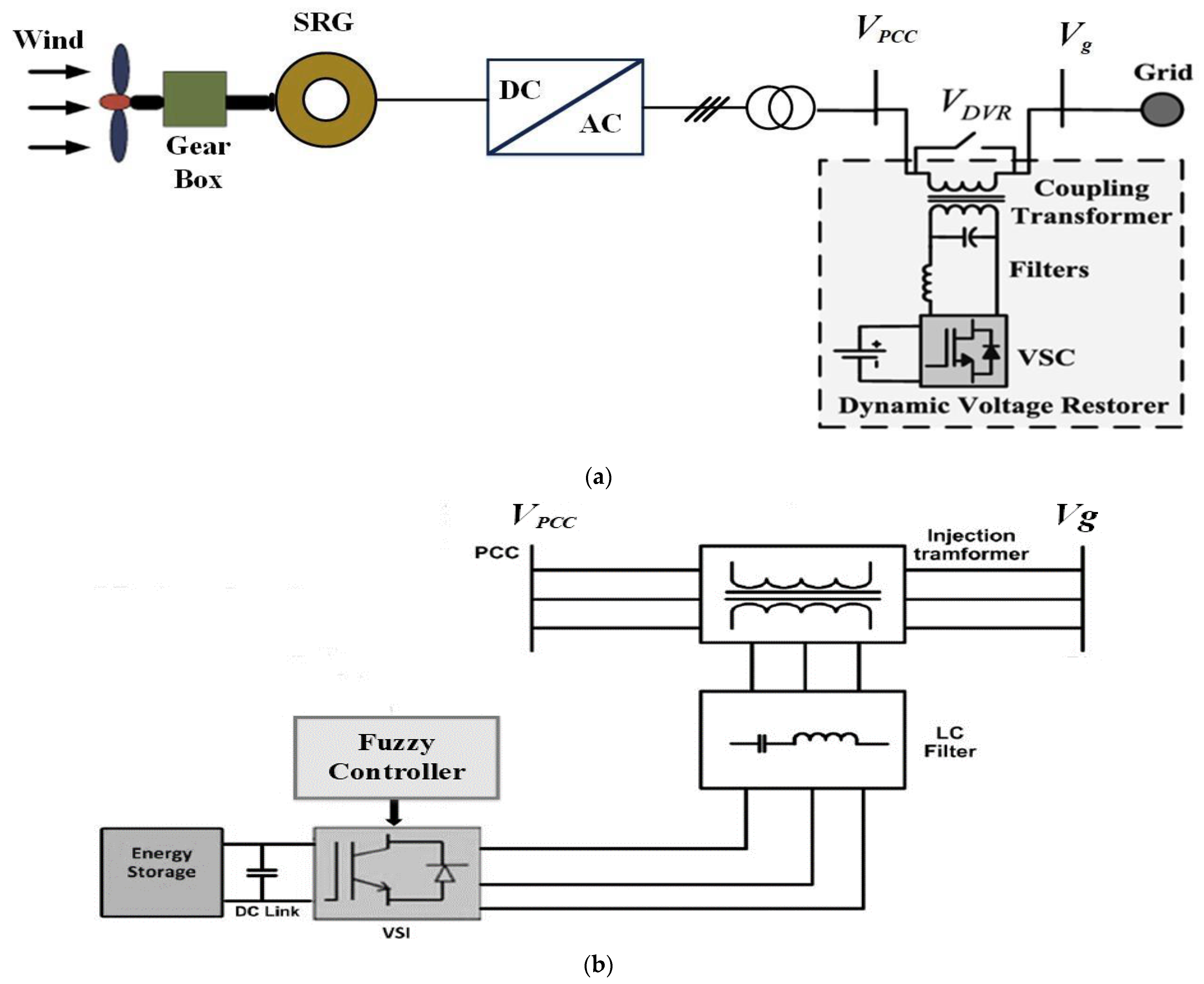
  • To introduce a FRT capability enhancement using a DVR for a WT based on an SRG.
  • To improve the stator voltage of an SRG during grid failures and implement the DVR to inject voltage at the PCC.
  • To propose a control strategy using a FLC for the DVR to enhance the capability of LVRT and to accomplish the codes of the grid without disconnecting the turbine.
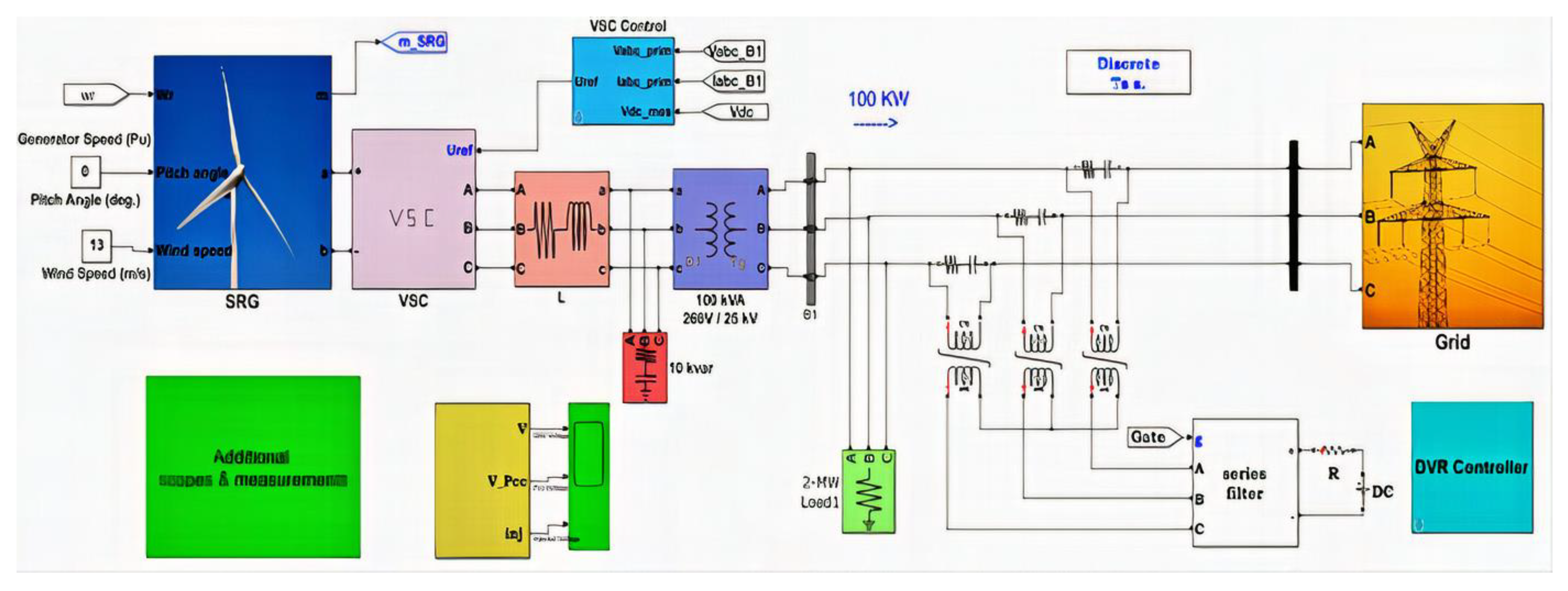
  • To validate the effectiveness and enactment of the suggested methodology under four test scenarios.
The remainder of the paper is structured as follows. Section 2 presents modelling of the SRG. Section 3 introduces DVR modelling. Section 4 introduces the control techniques of the DVR. The FLC strategy is explained in Section 5. Section 6 provides the simulation outcomes and discussions. The conclusion of the paper is provided in Section 7.

2. Modelling of 12/8 SRG

The stator of the SRG is comprised of a salient pole with a laminated core and concentrated windings. In addition, the rotor has a salient pole construction independent of windings or permanent magnets, resulting in cost savings and supply chain security, which are two important advantages [4,22]. There are many configurations for SRG. Figure 2a depicts the three-phase SRG’s structure for this paper, which has 12 poles on the stator and 8 poles on the rotor. Phase commutation and current regulation in 12/8 SRG are controlled by asymmetric bridge converters [4,23]. Half-bridge inverters, as depicted in Figure 2b, are a typical converter structure for this purpose.
It is possible to transform mechanical energy into electrical energy via electromechanical energy conversion, which is a bi-directional process. In wind turbines, the generator’s shaft is driven by the wind power [23]. Mechanical energy is transformed into electrical energy by controlling the phase currents through the inverter. Consequently, it is possible to adjust the output voltage and the current provided to the load [24].
When each phase is arbitrarily energized in the lowering region of the inductance profile at a specific conduction angle, a switched reluctance machine runs in the generating mode. Additionally, the electromagnetic torque equation, which depends on the inductance change rate, is used to support this [24]:
T = 1 2 i j 2   d L θ d θ
where, L is the phase inductance, which varies as a function of both the current, ij and rotor position, θ.
The SRG output power is calculated by adding the output power (Pout) of each phase in a single electric cycle [15].
P o = 1 T   j = 1 N s 0 T v j   i j   d t  
where, Ns, T, vj, ij denote the number of motor phases, the conduction period of one phase, and the voltage and current of Phase j, respectively. The formula of SRG voltage is as follows:
V j = i j R + d λ j d t
where R denotes the resistance of phase, λj denotes the flux linkage of phase j owing to current ij, and t denotes the time. The λj defined as
λ j = L j i j , θ   i j
The performance of the SRG further down the system’s typical functionality is displayed in Figure 3 using MATLAB/SIMULINK software. It displays the output voltage, current, and power generated by SRG.

3. DVR Modeling

Basically, the DVR is a voltage-source inverter that generates AC output voltage and injects it in series with the SRG’s terminal voltage. The suggested system in this paper is shown in Figure 4a. In contrast, DVR was implemented in the system as seen in Figure 4b to mitigate the disruption [11,25].
By injecting the necessary compensation voltage, the stator-terminal voltages of the SRG are maintained constant at the proper (pre-fault) magnitude through the control of the DVR, as shown in Figure 5. The DVR controller is made up of three single-phase controllers to provide independent control of the voltage compensation of each phase. As a result, the DVR in this instance is managed using the abc coordinate system. This will also enable the SRG to overcome faults [11,25]. In the dq reference frame, the phase-locked loop (PLL) senses the angle of phase for the grid and is used for synchronization. The approach of in-phase compensation is used. DVR for wind turbine power is appreciated due to the grid codes’ requirement for full-voltage sag compensation during fault conditions [26].
The DVR power rating regulated through the approach of in-phase compensation is: [11],
S D V R = K = a , b , c V D V R , k r e f I L
V D V R , k r e f is the RMS injected voltage of DVR in phase k and IL is the load current for RMS. Between the grid and the DVR, there is an active power reciprocation of [11]
P D V R = P L P g = 3 V L I L cos γ K = a , b , c [   V D V R , k r e f I L cos γ ]
and     V D V R , k r e f = 2   V L V g , k r e f   a n d   K = a , b , c
where Vg is the grid voltage, ψ is the difference phase angle between load voltage and load current phasors, VL is the load voltage and IL load current prior sag, V’g is the grid voltage, V’L is the load voltage and I’L load current after sag, VDVR is the DVR compensation voltage [11].
The DVR structure is located between the Vg bus and the VL load bus. It acts as a PQ conditioner to enhance voltage, manage reactive power, and decrease harmonic distortion in real time [27]. The three single-phase boosting transformers’ AC sides have a number of capacitors (Cs) linked there to form the DVR. A capacitor bank is put in series with a series resistance Rs to regulate power flow [15,28].

4. Control Techniques of DVR

The detection of the beginning and conclusion of a failure case, the creation of references, the regulation of the injected voltage, both in temporary and permanent states, and the safeguarding of the equipment are encompassed within the control of DVR. The grid-side pre-sag voltage before DVR is used to estimate the voltage decrease during the fault in the feed-forward control. The feedback control monitors the SRG side’s voltage mitigation after DVR. Converter protection is controlled by the voltage of the DC link [29]. This combined control provides feedback that takes the filter-induction voltage drop and transformer into account [30,31]. The Matlab/Simulink platform of the DVR controller is presented in Figure 6.

5. Fuzzy Control Strategy

Power-system-control applications are better suited for nonlinear controllers like FLC [31]. They can adapt to a wider range of operating situations and are simple to develop and apply. Automatic membership function refinement is possible with self-organized fuzzy controllers [32]. The system is modelled linearly in traditional process-based control techniques, which makes it impossible to guarantee respectable performance across a large range of tasks. There are two steps to the fuzzy procedure: fuzzification and defuzzification. The process of turning a crisp input into a fuzzy value is called fuzzification. Utilizing the rules, the fuzzy output is created. Fuzzy control rules, which are based on FLC, employ the value of fuzzy sets typically for error and change of error and control action. Combining the findings to provide a clear output while managing the output variable is known as defuzzification [33]. With seven linguistic variables, error and its derivative are exits in FLC.
The membership functions and the partition of fuzzy subsets are depicted in Figure 7. This arrangement’s membership functions have a triangle form.

6. Results and Discussion

Simulation outcomes under LVRT by DVR are deliberated. The obtainable on the MATLAB/SIMULINK system, DVR is investigated to enhance various fault conditions for the power system illustrated in Figure 8 to control the SRG’s voltage driven by WT. The intended DVR has a power of 0.5 MVA coupled to 25 kV distribution network.
The DVR is in standby mode as part of its normal operation. The compensation voltage required by the DVR is currently being inserted and is then controlled to maintain the stator terminal voltages of the SRG at the proper (pre-fault) magnitude, as will be shown in all cases. Table 1 shows the SRG and DVR simulation parameters. To evaluate the proposed FRT control method, the PCC findings have been provided. The efficiency of the WT-LVRT will be analyzed and evaluated in the upcoming scenarios:
  • Scenario 1/Balanced sag of 0.5 p.u.
  • Scenario 2/Unbalanced sag of 0.5 p.u.
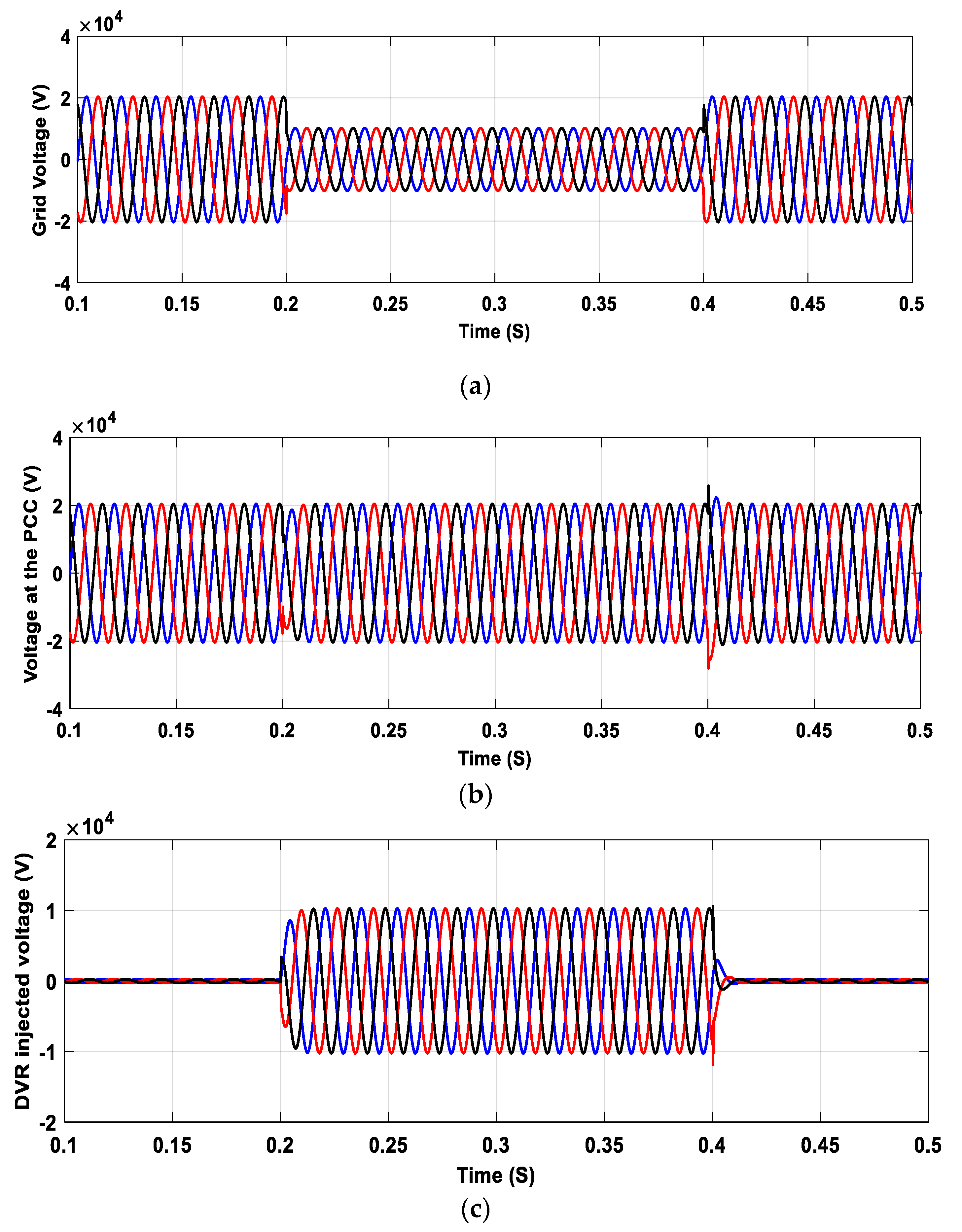
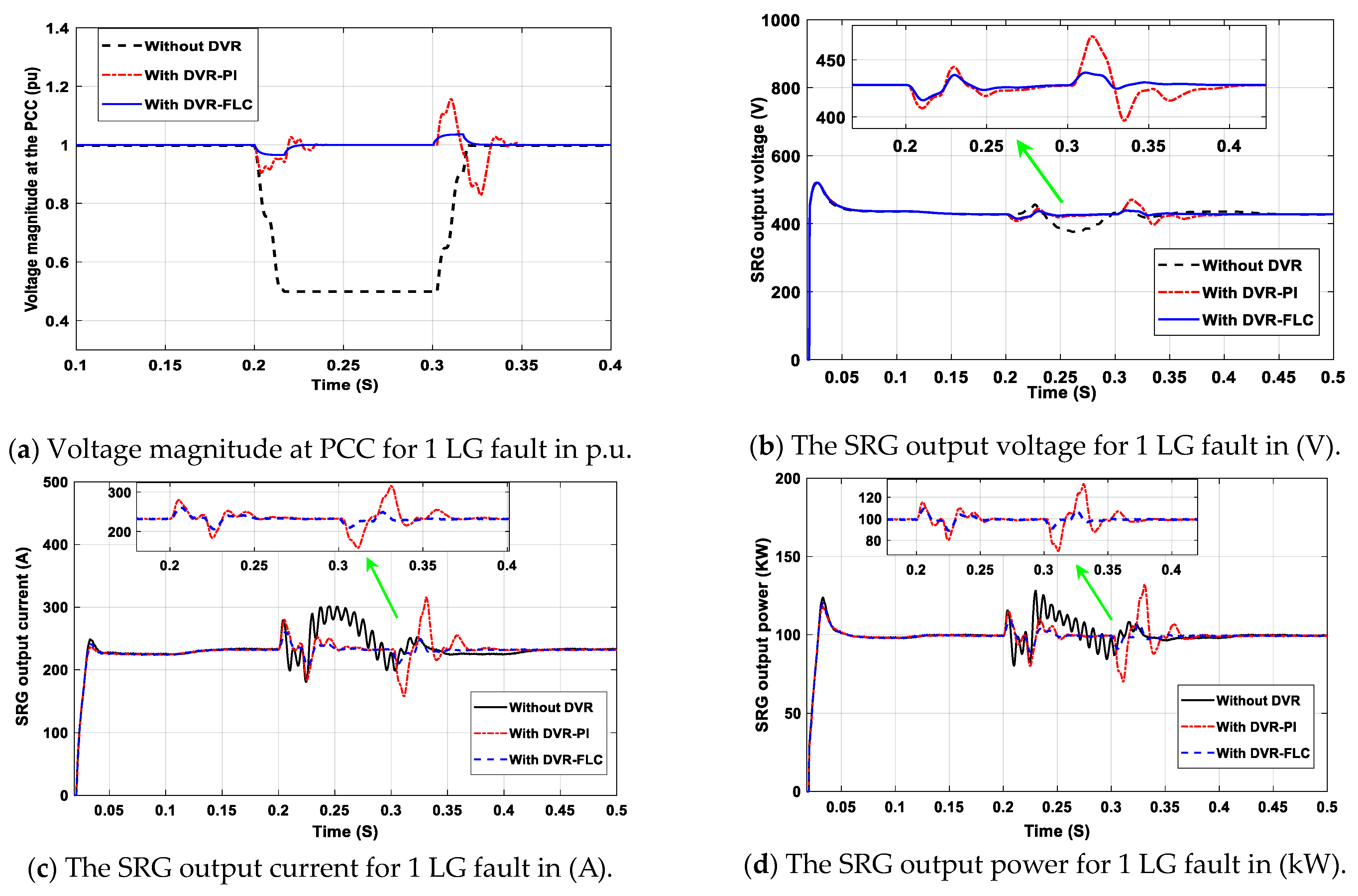
  • Scenario 3/Single line—ground fault, 1 LG.
  • Scenario 4/Analysis of harmonics spectrum.

6.1. Scenario 1: Balanced Voltage Sag

The voltage sag is the most common type of grid disturbance due to sudden switching on large inductive loads, similar to starting the motor of an electrical heater. In this case, the symmetrical voltage sag of 50% is made in the side of the grid at t = 0.2 s to 0.4 s. A similar voltage sag is produced when attaching the DVR to the PCC; the necessary compensation voltage is injected by the DVR, which is then controlled to maintain the stator terminal voltages of the SRG at the proper magnitude. The balanced sag voltage on the grid side is displayed in volts in Figure 9a. The voltage at PCC is displayed in volts in Figure 9b,c displays the voltage injected by DVR in (V).
To simulate and compare transient behaviors of the SRG in the sag mode, both FLC and PI controller control systems based on DVR-based series compensation are used. In this sag mode, the responses of the system under study are depicted in Figure 10. As shown in Figure 10a, the PCC voltage is adjusted to 1 p.u. through a slight overshoot. It is also found that by using DVR with FLC, the overshoot and oscillation can be reduced more effectively than with a PI controller. Figure 10b depicts the SRG’s output voltage in volts. After 1 cycle of oscillations, or roughly 0.016 s, a minor overshoot occurs before the voltage reaches a steady state. Figure 10c,d display the current and power delivered to the grid by SRG. These figures demonstrate the significant oscillations that occurred during the sag disturbance period without the DVR. Additionally, utilizing DVR with FLC, it is demonstrable that the current or power exhibits slight overshoots and oscillations for 0.04 s (2.5 cycles), after which it is totally damped. According to the simulation’s findings, the SRG wind turbine is successfully shielded against transient voltages and currents by the FLC-based DVR-based series compensation.

6.2. Scenario 2: Unbalanced Voltage Sag

At 0.2 s to 0.4 s, an overload occurs in phase A, and the voltage at the Vg bus is reduced to 50% phase A with respect to the reference voltage. The grid-side unbalanced sag voltage in (V) is displayed in Figure 11a. Figure 11b depicts the PCC voltage after compensation in (V), and Figure 11c displays the DVR injection voltage in (V).
As seen in Figure 11b, the DVR quickly identifies this sag state in various phases and injects the necessary voltage to keep PCC voltage in balance. Figure 12a displays the dynamic responses of the system under study for PCC voltage, Figure 12b, the output voltage of SRG, Figure 12c, current injected from SRG, and Figure 12d, output power from the SRG.
The voltage magnitude in p.u. is displayed in Figure 12a at PCC through the unbalanced sag. The voltage is thereby tightly controlled to 1 p.u. for both control systems, with a slight overshoot below the safety limits. The FLC scheme appears to be able to minimize overshooting and oscillation more successfully than the PI method. In Figure 12b, SRG output voltage in volts is displayed. A minor overshoot occurs before the voltage reaches a steady state after one cycle of oscillations, or roughly 0.016 s. The SRG WT’s current injection into the grid at PCC is shown in Figure 12c. The current rises from 230 A to 300 A in the absence of the DVR. The current is totally damped when using DVR that is FLC-based, with very minor overshoots and oscillations. Figure 12d shows the power generated by the SRG. If the DVR is not present during the unbalanced sag, the power rises to 110 kW by significant oscillations until the unbalanced sag ends. In addition to reducing overhead and oscillating active power, DVR based on FLC also responds more quickly and is unaffected by disruptions that occur on the grid side.

6.3. Scenario 3: Single Line to Ground Fault (1 LG)

At t = 0.2 s for 0.1 s (6 cycles at 60 HZ), a 1 LG occurs at the grid side during phase A. When the same fault occurs when the DVR is connected at the PCC, the suitable amount of voltage is delivered into all three phases by the DVR, resulting in an improved voltage profile at the PCC. Figure 13a displays the grid voltage in (V) with a 1 LG fault. The PCC voltage after compensation in (V) is shown in Figure 13b and the injection voltage of DVR in (V) in Figure 13c. The examined SRG wind turbine’s transient behaviors with DVR-based series compensation under a 1 LG fault are simulated and contrasted using the control strategies FLC and PI controller, respectively.
In Figure 14, the dynamic responses of the system under study during this 1 LG fault are depicted. Based on the findings illustrated in Figure 14a, it can be observed that the FLC system results in a slight overshoot before the voltage stabilizes when compared to the PI system.
The SRG voltage is depicted in (V) in Figure 14b. After 0.04 s of oscillations, or roughly 2.5 cycles using the FLC technique, the stable state is achieved when the voltage narrowly exceeds the required threshold. But using the PI scheme, the voltage reaches the steady state with high overshoot and oscillations for 0.09 s after the start of the fault and 0.1 s after the end of the fault.
The SRG current at PCC injected into the grid is depicted in Figure 14c. The current jumped from its regular level of 230 A to 300 A in the absence of the DVR, when significant oscillations were visible. Also, it can be seen that the current is regulated closely to the rated value 230 A relative to the PI system. The FLC scheme had a slight overshoot that was below the safety limits. The SRG output power at the PCC is depicted in Figure 14d. In the absence of DVR, with large oscillations, the power has increased to 130 kW. Additionally, compared to the PI scheme, it can be seen that the power is more precisely regulated to the 100 kW rated value, with just a slight overshoot below the safety limits. According to Figure 1 grid-code curves, the results of the simulation show an agreement between these standards. These values recovered within the recovery limits in a reasonable amount of time.

6.4. Scenario 4: Analysis of Harmonic Distortion

It is essential to gauge the degree of harmonic distortion in the voltage or current waveforms because total harmonic distortion (THD) has significant negative harmonics that accompany the majority of grid disturbances for the system [34,35]. The recommended DVR is used to investigate the THD values.
Figure 15 displays the THD measuring the PCC voltages and currents with sag disturbance. To demonstrate the success of the suggested DVR techniques, it is evident that utilizing DVR with FLC, the THD of the voltage and current values is greatly decreased to fall within the permitted limits specified in IEEE 519 [36].
Table 2 provides a comparison of FLC, PI, and DVR used for harmonic mitigation. It displays a noteworthy enhancement in the concert of the DVR with FLC.

7. Conclusions and Future Work

This paper examined the efficiency of DVR in SRG to achieve FRT capability and maintain normal turbine performance in the event of grid faults. During balanced sag mode, the DVR with FLC controller at the PCC mode enhanced the voltage magnitude, the current, and the power through a minor overshoot and oscillations. During unbalanced sag mode, the voltage, current and power were faithfully controlled to 1 p.u with minor overshoots and oscillations. During 1 LG fault, with a small overshoot, the voltage attains the steady state after 0.04 s of oscillations, the current is regulated closely to the rated value 230 A, and the power is regulated closely to the rated value 100 kW with a small overshoot. It is evident that in utilizing DVR with FLC, the THD is greatly decreased to fall within the permitted limits specified in IEEE 519 standards for the voltage and current values. The results of simulation using a wind turbine based on SRG with an electric grid display the good performance of DVR with the FLC for the FRT improvement.
In future work, the efficiency of DVR in SRG-based wind turbines to achieve both FRT capability and maintain normal turbine performance in the event of various grid faults must be studied with large-scale wind turbines. Generally, in the best practice, such complex compensators used in wind turbines with a large scale (more than 3 MW capacity) in terms of economical perspective will be studied. In addition, experimental validation will be studied in future work.

Funding

This work was supported by the Deputyship for Research & Innovation, Ministry of Education in Saudi Arabia for funding this research work through the project number MOE-BU-8-2020.

Institutional Review Board Statement

Not applicable.

Informed Consent Statement

Not applicable.

Data Availability Statement

Data are available on request from the authors.

Acknowledgments

The authors extend their appreciation to the Deputyship for Research & Innovation, Ministry of Education in Saudi Arabia for funding this research work through the project number: MOE-BU-8-2020.

Conflicts of Interest

The authors declare no conflict of interest.

Abbreviations

Abbreviations
1 LGSingle line to ground
CFConstant frequency
CFDRGConstant frequency (CF)-type double rotor generator
CFFFBCombined feed-forward and feed-back
DFIGDouble-fed induction generator
DVRDynamic voltage restorer
ERCEnergy regulatory commission
FACTSSeries flexible ac transmission systems
FERCFederal energy regulatory commission
FLCFuzzy logic controller
HVRTHigh voltage ride-through.
LVRTLow voltage ride-through.
MLIMulti-level inverter
NBNegative-big
NMNegative-medium
NSNegative-small
OCAMLIOdd-nary cascaded asymmetric-type MLI
PBPositive-big
PCCPoint of common coupling
PIProportional integral
PLLPhase-locked loop
PMPositive-medium
PSPositive-small
PWMPulse-width modulation
SFCLSuper-conducting fault current limiters
SRGSwitched reluctance generator
STATCOMStatic synchronous compensator
TCVRThyristor-controlled voltage regulator
THDTotal harmonic distortion
VSIVoltage source inverter
WTWind turbine
ZEZero
Parameters
CsSeries capacitor
ijCurrent of phase j
ILLoad current for RMS
ILCurrent of load prior sag
I’LLoad current after sag
LjSelf-inductance of phase j
NsNumber of motor phases
PDVRDVR compensation power
PgLoad active power rating
PLLoad active power rating
PoutOutput power
RWinding resistance per phase
RsSeries resistor with a capacitor bank
SDVRDVR apparent power rating
TConduction period
VDVRDVR compensation voltage
V D V R , k r e f RMS injected voltage of DVR in phase k
VgGrid voltage
V’gGrid voltage
vjThe voltage of phase j
VLVoltage of load
V’LLoad voltage
θPosition of the rotor related to the aligned position (θ = 0o).
λjFlux linkage of phase j
ψ The difference phase angle between load voltage and load current

References

  1. Wu, Z.; Zhu, C.; Hu, M. Improved Control Strategy for DFIG Wind Turbines for Low Voltage Ride Through. Energies 2013, 6, 1181–1197. [Google Scholar] [CrossRef] [Green Version]
  2. Gao, D.W.; Muljadi, E.; Tian, T.; Miller, M.; Wang, W. Comparison of Standards and Technical Requirements of Grid-Connected Wind Power Plants in China and the United States; National Renewable Energy Lab. (NREL): Golden, CO, USA, 2016; Volume 50, pp. 553–561. [Google Scholar] [CrossRef] [Green Version]
  3. Robert, B.; Brown, E.B. United States of America Joint Report of the North American Electric Reliability. Available online: https://www.federalregister.gov/documents/2023/04/24/2023-08610/north-american-electric-reliability-corporation-joint-federal-state-task-force-on-electric (accessed on 19 May 2023).
  4. Bahy, M.; Nada, A.S.; Elbanna, S.H.; Shanab, M.A.M. Voltage control of switched reluctance generator using grasshopper optimization algorithm. Int. J. Power Electron. Drive Syst. (IJPEDS) 2020, 11, 75–85. [Google Scholar] [CrossRef] [Green Version]
  5. Rahmanian, E.; Akbari, H.; Sheisi, G.H. Maximum Power Point Tracking in Grid Connected Wind Plant by Using Intelligent Controller and Switched Reluctance Generator. IEEE Trans. Sustain. Energy 2017, 8, 1313–1320. [Google Scholar] [CrossRef]
  6. Energy, G. Technical Requirements for Wind Generation Interconnection and Integration. N. Engl. Wind. Integr. Study 2009, 3, 1–128. [Google Scholar]
  7. Chen, X.; Yan, L.; Zhou, X.; Sun, H. A Novel DVR-ESS-Embedded Wind-Energy Conversion System. IEEE Trans. Sustain. Energy 2018, 9, 1265–1274. [Google Scholar] [CrossRef]
  8. Liasi, S.G.; Afshar, Z.; Harandi, M.J.; Kojori, S.S. An Improved Control Strategy for DVR in order to Achieve both LVRT and HVRT in DFIG Wind Turbine. In Proceedings of the 10th International Conference and Exposition on Electrical and Power Engineering (EPE), Iasi, Romania, 18–19 October 2018; pp. 724–730. [Google Scholar] [CrossRef]
  9. Ghorbanian, M.J.; Goodarzvand, F.; Pourdaryaei, A.; Mahadi, W.N.L. Mitigating voltage sag by implementing STATCOM on DFIG-based wind farms connected to a power system. In Proceedings of the 4th International Conference on Engineering Technology and Technopreneuship (ICE2T), Kuala Lumpur, Malaysia, 27–29 August 2014; pp. 131–136. [Google Scholar] [CrossRef]
  10. Molinas, M.; Suul, J.A.; Undeland, T. Low Voltage Ride Through of Wind Farms with Cage Generators: STATCOM Versus SVC. IEEE Trans. Power Electron. 2008, 23, 1104–1117. [Google Scholar] [CrossRef]
  11. Jerin, A.R.A.; Prabaharan, N.; Palanisamy, K.; Umashankar, S. FRT Capability in DFIG based Wind Turbines using DVR with Combined Feed-Forward and Feed-Back Control. Energy Procedia 2017, 138, 1184–1189. [Google Scholar] [CrossRef]
  12. Wessels, C.; Gebhardt, F.; Fuchs, F.W. Fault Ride-Through of a DFIG Wind Turbine Using a Dynamic Voltage Restorer during Symmetrical and Asymmetrical Grid Faults. IEEE Trans. Power Electron. 2011, 26, 807–815. [Google Scholar] [CrossRef] [Green Version]
  13. Hasanien, H.; Muyeen, S.; Al-Durra, A. Adaptive Control Strategy for Low Voltage Ride Through Capability Enhancement of a Grid-Connected Switched Reluctance Wind Generator. In Proceedings of the 5th IET International Conference on Renewable Power Generation (RPG) 2016, IET, London, UK, 21–23 September 2016; pp. 1–6. [Google Scholar] [CrossRef] [Green Version]
  14. Farhadi-Kangarlu, M.; Babaei, E.; Blaabjerg, F. A comprehensive review of dynamic voltage restorers. Int. J. Electr. Power Energy Syst. 2017, 92, 136–155. [Google Scholar] [CrossRef]
  15. Asadi, P. Development and Application of an Advanced Switched Reluctance Generator Drive; Texas A&M University: College Station, TX, USA, 2006. [Google Scholar]
  16. Falehi, A.; Rafiee, M. Enhancement of DFIG-Wind Turbine’s LVRT capability using novel DVR based Odd-nary Cascaded Asymmetric Multi-Level Inverter. Eng. Sci. Technol. Int. J. 2017, 20, 805–824. [Google Scholar] [CrossRef]
  17. Falehi, A.D.; Torkaman, H. Promoted supercapacitor control scheme based on robust fractional-order super-twisting sliding mode control for dynamic voltage restorer to enhance FRT and PQ capabilities of DFIG-based wind turbine. J. Energy Storage 2021, 42, 102983. [Google Scholar] [CrossRef]
  18. Din, Z.; Zhang, J.; Xu, Z.; Zhang, Y.; Zhao, J. Realization of fault ride through for doubly fed induction generator system with cascade converter. Int. Trans. Electr. Energy Syst. 2021, 31, e12792. [Google Scholar] [CrossRef]
  19. Chhipą, A.A.; Chakrabarti, P.; Bolshev, V.; Chakrabarti, T.; Samarin, G.; Vasilyev, A.N.; Ghosh, S.; Kudryavtsev, A. Modeling and Control Strategy of Wind Energy Conversion System with Grid-Connected Doubly-Fed Induction Generator. Energies 2022, 15, 6694. [Google Scholar] [CrossRef]
  20. Din, Z.; Su, D.; Zhang, J.; Xu, Z. Operation and Evaluation of Wind Power Generation System with Constant Frequency Double Rotor Generator. In Proceedings of the 2020 7th International Conference on Electrical and Electronics Engineering (ICEEE), Antalya, Turkey, 14–16 April 2020; pp. 130–136. [Google Scholar]
  21. Touati, Z.; Pereira, M.; Araújo, R.E.; Khedher, A. Integration of Switched Reluctance Generator in a Wind Energy Conversion System: An Overview of the State of the Art and Challenges. Energies 2022, 15, 4743. [Google Scholar] [CrossRef]
  22. Ramkumar, M.; Latha, K. Analysis of Maximizing the Power Output of Switched Reluctance Generator Using Different Core Materials. Adv. Mater. Sci. Eng. 2023, 2023, 8539809. [Google Scholar] [CrossRef]
  23. Reis, M.R.C.; Calixto, W.P.; Araujo, W.R.H.; Matias, C.A. Increasing efficiency of the switched reluctance generator using parametric regression and optimization methods. In Proceedings of the 18th International Scientific Conference on Electric Power Engineering (EPE), Kouty nad Desnou, Czech, 17–19 May 2017; pp. 1–6. [Google Scholar] [CrossRef]
  24. Berker, B.; Jiang, J.W.; Emadi, A. (Eds.) Switched Reluctance Motor Drives Fundamentals to Applications, 1st ed; CRC Press: Boca Raton, FL, USA, 2018; ISBN 9781138304598. [Google Scholar] [CrossRef]
  25. Gonzalez, M.; Cardenas, V.; Moran, L.; Espinoza, J. Selecting between linear and nonlinear control in a dynamic voltage restorer. Simul. Model. Pract. Theory 2014, 47, 221–235. [Google Scholar] [CrossRef]
  26. González, M.; Cárdenas, V.; Espinosa, G. Advantages of the passivity based control in dynamic voltage restorers for power quality improvement. Simul. Model. Pract. Theory 2014, 47, 221–235. [Google Scholar] [CrossRef]
  27. Sindi, H.F.; Alghamdi, S.; Rawa, M.; Omar, A.I.; Elmetwaly, A.H. Robust control of adaptive power quality compensator in Multi-Microgrids for power quality enhancement using puzzle optimization algorithm. Ain Shams Eng. J. 2023, 14, 102047. [Google Scholar] [CrossRef]
  28. Omar, A.I.; Aleem, S.H.A.; El-Zahab, E.E.; Algablawy, M.; Ali, Z. An improved approach for robust control of dynamic voltage restorer and power quality enhancement using grasshopper optimization algorithm. ISA Trans. 2019, 95, 110–129. [Google Scholar] [CrossRef]
  29. Abu Hussein, A.; Ali, M.H. Comparison among series compensators for transient stability enhancement of doubly fed induction generator based variable speed wind turbines. IET Renew. Power Gener. 2016, 10, 116–126. [Google Scholar] [CrossRef]
  30. Mohsen, S.E.A.; Ibrahim, A.M.; Elbarbary, Z.M.S.; Omar, A.I. Unified Power Quality Conditioner Using Recent Optimization Technique: A Case Study in Cairo Airport, Egypt. Sustainability 2023, 15, 3710. [Google Scholar] [CrossRef]
  31. Aldin, N.A.N.; Abdellatif, W.S.E.; Elbarbary, Z.M.S.; Omar, A.I.; Mahmoud, M.M. Robust Speed Controller for PMSG Wind System Based on Harris Hawks Optimization via Wind Speed Estimation: A Real Case Study. IEEE Access 2023, 11, 5929–5943. [Google Scholar] [CrossRef]
  32. Rashid, G.; Ali, M.H. Nonlinear Control-Based Modified BFCL for LVRT Capacity Enhancement of DFIG-Based Wind Farm. IEEE Trans. Energy Convers. 2017, 32, 284–295. [Google Scholar] [CrossRef]
  33. Benali, A.; Khiat, M.; Allaoui, T.; Denai, M. Power Quality Improvement and Low Voltage Ride Through Capability in Hybrid Wind-PV Farms Grid-Connected Using Dynamic Voltage Restorer. IEEE Access 2018, 6, 68634–68648. [Google Scholar] [CrossRef]
  34. Yahiya, M.A.A.; Uzair, M.A.R. Performance analysis of DVR, DSTATCOM and UPQC For improving the power quality with various control strategies. In Proceedings of the 2007 IEEE Power Engineering Society General Meeting, Tampa, FL, USA, 24–28 June 2007; pp. 1–8. [Google Scholar]
  35. Sakar, S.; Balci, M.E.; Aleem, S.H.E.A.; Zobaa, A.F. Hosting capacity assessment and improvement for photovoltaic-based distributed generation in distorted distribution networks. In Proceedings of the IEEE 16th International Conference on Environment and Electrical Engineering (EEEIC), Florence, Italy, 7–10 June 2016; pp. 1–6. [Google Scholar]
  36. IEEE Std. 519-2014; IEEE Recommended Practice and Requirements for Harmonic Control in Electric Power Systems. IEEE Std.: Piscataway, NJ, USA, 2014.
Figure 1. United States requirements for LVRT (FERC Order No. 661) [3].
Sustainability 15 11061 g001
Figure 2. Overall cross-sectional view of the 12/8 SRG: (a) Structure of machine and (b) A 3-ph SRG asymmetric half-bridge converter [4].
Sustainability 15 11061 g002
Figure 3. The performance of the SRG during regular system functioning: the output voltage, current, and power generated by SRG.
Sustainability 15 11061 g003
Figure 4. The Wind system block diagram and DVR modules: (a) Wind system block diagram with DVR and (b) DVR modules.
Sustainability 15 11061 g004
Figure 5. The DVR compensation scheme based on in-phase compensation.
Sustainability 15 11061 g005
Figure 6. Matlab simulation model of the proposed DVR controller.
Sustainability 15 11061 g006
Figure 7. Membership functions’ form and fuzzy subsets.
Sustainability 15 11061 g007
Figure 8. System simulation model created in MATLAB.
Sustainability 15 11061 g008
Figure 9. Results of simulations: Balanced sag voltage (a) voltage at G-bus in (V), (b) compensated voltage at PCC in (V), and (c) injected voltage by DVR in (V).
Sustainability 15 11061 g009
Figure 10. The responses of the system under study: (a) Voltage magnitude in p.u. (b) SRG output voltage in V (c) SRG output current in A (d) SRG output power in kW.
Sustainability 15 11061 g010
Figure 11. Results of simulations: Unbalanced sag voltage (a) voltage at G-bus in (V), (b) compensated voltage at PCC in (V), and (c) injected voltage by DVR in (V).
Sustainability 15 11061 g011
Figure 12. The responses of the system under study: (a) Voltage magnitude in p.u. (b) SRG output voltage in V (c) SRG output current in A (d) SRG output power in kW.
Sustainability 15 11061 g012
Figure 13. Results of simulations: 1 LG fault (a) voltage at G-bus in (V), (b) compensated voltage at PCC in (V), and (c) injected voltage by DVR in (V).
Sustainability 15 11061 g013
Figure 14. The responses of the system under study: (a) Voltage magnitude in p.u. (b) SRG output voltage in V (c) SRG output current in A (d) SRG output power in kW.
Sustainability 15 11061 g014
Figure 15. Voltage and current at the PCC bus using FFT: (a) THDv at VPCC with DVR-PI during sag mode, (b) THDv at VPCC with DVR-FLC during sag mode, (c) THDi with DVR-PI during sag mode, (d) THDi with DVR-FLC during sag mode.
Sustainability 15 11061 g015
Table 1. Model Parameters.
DVR Data [27] Values SRG Data [4]Values
VDC2000 VVr500 V
R0.8 ΩT500 N.m
VSI3 arms, 6 pulsesPo110 kw
Carrier frequency4500 HzNs12
Shunt filter resistance50 ΩNr8
Shunt filter capacitance5 µFbase speed1150 r.p.m
series filter inductance75 mHRj0.025 Ω
series filter resistance0.9 ΩJ0.04 kg.m2
ratio of Boosting transformer 1:1B0.03 N.m.s
Table 2. Harmonic mitigation with DVR-PI and DVR-FLC.
Fault TypeTHD % ValuesWithout DVRDVR-PIDVR-FLC
Sag modePCC voltage20.39%5.15%2.73%
PCC current9.48%7.57%4.65%
1 LG faultPCC voltage30.36%18.34%2.38%
PCC current21%11.28%3.12%
Disclaimer/Publisher’s Note: The statements, opinions and data contained in all publications are solely those of the individual author(s) and contributor(s) and not of MDPI and/or the editor(s). MDPI and/or the editor(s) disclaim responsibility for any injury to people or property resulting from any ideas, methods, instructions or products referred to in the content.

