Article

Insights on the Performance of Nickel Foam and Stainless Steel Foam Electrodes for Alkaline Water Electrolysis

1
TecnoVeritas—Serviços de Engenharia e Sistemas Tecnológicos, Lda, 2640-486 Mafra, Portugal
2
Center of Physics and Engineering of Advanced Materials, Laboratory for Physics of Materials and Emerging Technologies, Chemical Engineering Department, Instituto Superior Técnico, Universidade de Lisboa, 1049-001 Lisbon, Portugal
3
CBIOS—Center for Research in Biosciences & Health Technologies, Universidade Lusófona de Humanidades e Tecnologias, Campo Grande 376, 1749-024 Lisbon, Portugal
4
CERENA—Centre for Natural Resources and the Environment, Instituto Superior Técnico, Universidade de Lisboa, Av. Rovisco Pais, 1049-001 Lisbon, Portugal
5
CiiEM—Centro de Investigação Interdisciplinar Egas Moniz, Campus Universitário, Quinta da Granja, 2829-511 Caparica, Portugal
*
Author to whom correspondence should be addressed.
Sustainability 2023, 15(14), 11011; https://doi.org/10.3390/su151411011
Submission received: 28 April 2023 / Revised: 5 July 2023 / Accepted: 12 July 2023 / Published: 13 July 2023

Abstract

:
Green hydrogen production seems to be the best route to achieve a sustainable alternative to fossil fuels, as hydrogen has the highest energy density on a mass basis and its combustion does not produce greenhouse gases. Water electrolysis is the method of choice for producing green hydrogen. Among commercially available water electrolysis systems, alkaline water electrolysis (AWE) is the most well-established technology, which, nevertheless, still needs to improve its efficiency. Since the electrodes’ performance is of utmost importance for electrolysis efficiency, nickel foam (NF) and stainless steel foam (SSF) electrodes were analyzed via voltammetry to validate their catalytic activity toward the hydrogen evolution reaction (HER) and oxygen evolution reaction (OER) in 30 wt.% NaOH electrolyte solution. Moreover, at a current density of 50 mA cm−2, the NF and the SSF exhibited good stability, with the potential for HER and OER stabilizing at −0.5 V and 1.6 V vs. reversible hydrogen electrode. A lab-scale electrolyzer attained current densities of 10, 20, and 50 mA cm−2 at small cell voltages of 1.70 V, 1.80 V, and 1.95 V. The results validated NF and SSF as electrodes for a high-performance AWE electrolyzer, especially at higher temperatures. They ensured the progress for the project’s next stage, i.e., constructing an electrolyzer at a pilot scale.

1. Introduction

Due to population increase, growing energy demand severely threatens the global economy, as well as the environment, consequently leading to climate change. For the past one hundred years, fossil fuels have been, by far, the principal source of energy. As these are non-renewable sources, and their consumption produces massive emissions of greenhouse gases (GHG), replacing them with alternative clean energy resources is imperative. Hydrogen is critical for developing clean and sustainable energy systems [1,2,3,4]. Yet, hydrogen represents a modest fraction of the energy mix, and only 4% of the global hydrogen supply comes from clean sources [5,6].
Water electrolysis leads among the methods that use renewable energy to produce hydrogen [7]. In fact, by definition, hydrogen can only be called green if produced by water electrolysis using renewable energy sources [8]. But for a hydrogen economy based on water electrolysis to thrive, the available technologies still require further improvement to be considered competitive compared to hydrogen production from fossil fuels [9]. Alkaline water electrolysis (AWE) is the oldest and best well-established technique for producing high-purity hydrogen [10]. Among commercially available technologies, AWE is the one that offers high production rates at low costs of production and, because of that, is the technique more often used in large-scale water electrolysis systems [3,11,12]. However, a significant amount of work remains to be done to bridge the gaps between the extensive fundamental research on water electrolysis and its practical industrial applications [13,14,15].
The benchmark electrocatalysts for HER and OER are platinum (Pt) and ruthenium/iridium oxide (RuO2/IrO2) due to their low overpotential and Tafel slope. However, these metals are rare and expensive, which limits their large-scale practical application [16]. Nickel (Ni) and its alloys are suitable replacements for these noble metals because they exhibit the highest activity, with the advantages of being stable in strongly alkaline solutions, abundant, and inexpensive [16,17,18,19,20,21,22]. Hence, nickel foam (NF) is usually present as a substrate; however, it also has excellent catalytic behavior toward HER in alkaline media [23]. Regarding OER, the reaction mechanism is more complex [11], and metallic Ni still accounts for higher overpotentials and lower stability. But stainless steel (SS), as an alloy of Ni, iron (Fe), chromium (Cr), and other metals, is a suitable candidate for OER; in addition to its catalytic effect, it is also abundant, inexpensive, corrosion-resistant, and has excellent mechanical strength [23,24,25,26,27].
This study fits within the scope of ongoing studies of a Portuguese company (TecnoVeritas, Marfa, Portugal) pioneering the development of a pilot-scale high-efficiency alkaline water electrolyzer. The electrolyzer incorporates several features that increase its efficiency, making it an innovative technology compared to the current commercially available electrolyzers. These include (i) the high working pressure of 30 bar, which drastically reduces the energy required to compress the gases to storage pressure; (ii) the high turbulence generated inside the cells, which facilitates the release of the gas bubbles from the surface of the electrodes, allowing greater availability of the electrode surface for electrolysis; (iii) the use of a high-performance diaphragm; (iv) the zero-gap cell configuration to minimize the interelectrode distance and, therefore, the electrolyte resistance; and (v) an electrical supply without harmonic distortion. The zero-gap configuration in AWE involves pressing two porous electrodes on each side of the diaphragm, not allowing any gap between them, which significantly reduces the ohmic resistance. The major difference between this configuration and a more traditional setup is the use of porous electrodes instead of solid metal plates. The zero-gap setup allows the easy detachment of the bubbles from the electrodes’ surface, reducing their contribution to the cell voltage [28]. Thus, the most noteworthy feature of the current project is the use of porous electrodes with high catalytic effect: NF and stainless steel foam (SSF) as cathode and anode materials, respectively. These highly porous electrodes were selected because of their large surface area, which greatly increases electrolyte penetration and facilitates the detachment of the gas bubbles produced, increasing their catalytic behavior [1,29,30].
As the electrocatalytic behavior of the electrode materials is one of the main factors influencing the efficiency of the electrolyzer, the choice of using NF and SSF electrodes must be validated. Cyclic voltammetry and linear scan voltammetry are typical electrochemical methods for evaluating electrodes’ activity [31]. Thus, these methods were used in the present study to validate the chosen materials by assessing their performance towards HER and OER at different temperatures. Besides their catalytic behavior, the foams’ stability in alkaline medium was also evaluated through chronopotentiometry. Since the foams showed excellent individual performance, their behavior toward the overall water electrolysis was also assessed. Furthermore, the experimental results will be further used to predict the polarization curves and hydrogen production rates of the high-efficiency electrolyzer developed at TecnoVeritas, using Matlab/Simulink software R2019a (MathWorks, Natick, MA, USA).

2. Materials and Methods

The performance of the NF (Nanoshel, NS6130-10-1093, Ni > 99.9 wt.%, 50PPI/3 mm, Wilmington, DE, USA) and SSF (Nanoshel, NS6130-10-1095, SS316 > 99.9 wt.%, 50PPI/3 mm, Wilmington, DE, USA) foam electrodes was studied individually using the experimental setups shown in Figure 1a,b. Cyclic voltammetry (CV), linear scan voltammetry (LSV), and chronopotentiometry (CP) electrochemical techniques were performed using a Squidstat Plus potentiostat/galvanostat from Admiral Instruments (Tempe, AZ, USA), controlled by the associated Squidstat user interface software. Electrochemical measurements were carried out in triplicate in a typical 3-electrode electrochemical glass cell containing 100 mL of 30 wt.% NaOH (Eka Chemicals, 98 wt.%, Bohus, Sweden) electrolyte solution (10 M, pH~15). All solutions were prepared using Millipore water. The cell temperature was thermostatically controlled by an Ultraterm 6000383 P-Selecta water bath (J.P. Selecta, S.A., Barcelona, Spain). The foams NF (9.98 cm2) and SSF (4.59 cm2) electrodes were employed as working electrodes, a platinum mesh (50 cm2) was used as a counter electrode for the CV and LSV techniques, a graphite electrode (4 cm2) was used as counter electrode for CP, and a saturated calomel electrode (SCE) from HANNA Instruments (Smithfield, RI, USA), model HI5412, was used as a reference electrode. The electrodes were carefully placed inside the cell to ensure an even current distribution. The NF/SSF working electrode was kept at a fixed distance from the platinum counter electrode (on the opposite side of the cell) and at 1 cm from the SCE reference. Electrical connections were made using typical copper cables for electrochemical measurements and new crocodile clips. The potentials measured against the SCE reference electrode were then converted to the reversible hydrogen electrode (RHE) scale using Equation (1), which is temperature-dependent. The term c1, corresponding to the potential of the SCE reference versus the standard hydrogen electrode, was obtained from an online calculator [32], and c2 = ln 10 (RT/F). All potential values given throughout the paper relate to the RHE scale.
ERHE = ESCE,sat + c1 + (c2 × pH)
The CV technique was used to record the complete voltammograms for both electrodes to study their redox behavior at 25 and 80 °C, and at different scan rates, 10, 50, and 100 mV s−1. The foams were also cycled in the non-Faradaic processes region, i.e., where the double-layer formation exists, to estimate their electrochemical active surface area (ECSA). Herein, the ECSA is expressed as the ratio of the double-layer capacitance for the foam, Cdl foam (µF), and for a smooth electrode, Cdl smooth (µF cm−2), Equation (2). The voltammograms were obtained at scan rates, ν, in the 10–100 mV s−1 range at 25 °C. The working electrode potential was swept between the open circuit potential (OCP) and 50 mV around this value. From the CVs, it is possible to calculate the average capacitive current, Idl. The linear slope of Idl as a function of ν makes it possible to determine Cdl foam using Equation (3),
ECSA = C dl   foam C dl   smooth
I dl   = I c + I a 2 = C dl dE dt
where Ic and Ia stand for the cathodic and anodic currents at the potential value in the middle of the selected potential window, respectively [33,34]. These latter tests were performed in more diluted solutions, namely 1 M NaOH (pH 14) for the NF and 0.1 M NaOH (pH 13) for the SSF.
The LSV technique was performed in the 25–80 °C range, starting at OCP and scanning the potential at 1 mV s−1 to the cathodic side for NF, and from OCP to the anodic side for SSF at 2 mV s−1. The CP for both electrodes was carried out at a constant current density of 50 mA cm−2 (absolute value) for 16 h at 25 °C. The electrodes’ performance towards the overall water splitting process was analyzed at 25 °C using the NF as the cathode and the SSF as the anode (Figure 1c) by running cell polarization curves at a potential scan rate of 2 mV s−1 from the open circuit voltage (OCV) until 2 V.
The electrochemical data incorporate the ohmic drop (iR) correction. The cell resistance was determined by adding the electrolyte resistance, R, to that of the electrical cables (0.4 Ω). The former was calculated using Equation (4), where ĸ (S cm−1) is the conductivity of the electrolyte solution, l (cm) is the distance between the reference and working electrodes, and A (cm2) is the working electrode surface area [35]. The ĸ of the 30 wt.% NaOH solution and the R for the NF and SSF electrodes are presented in Table 1.
R = l/(ĸA)

3. Results and Discussion

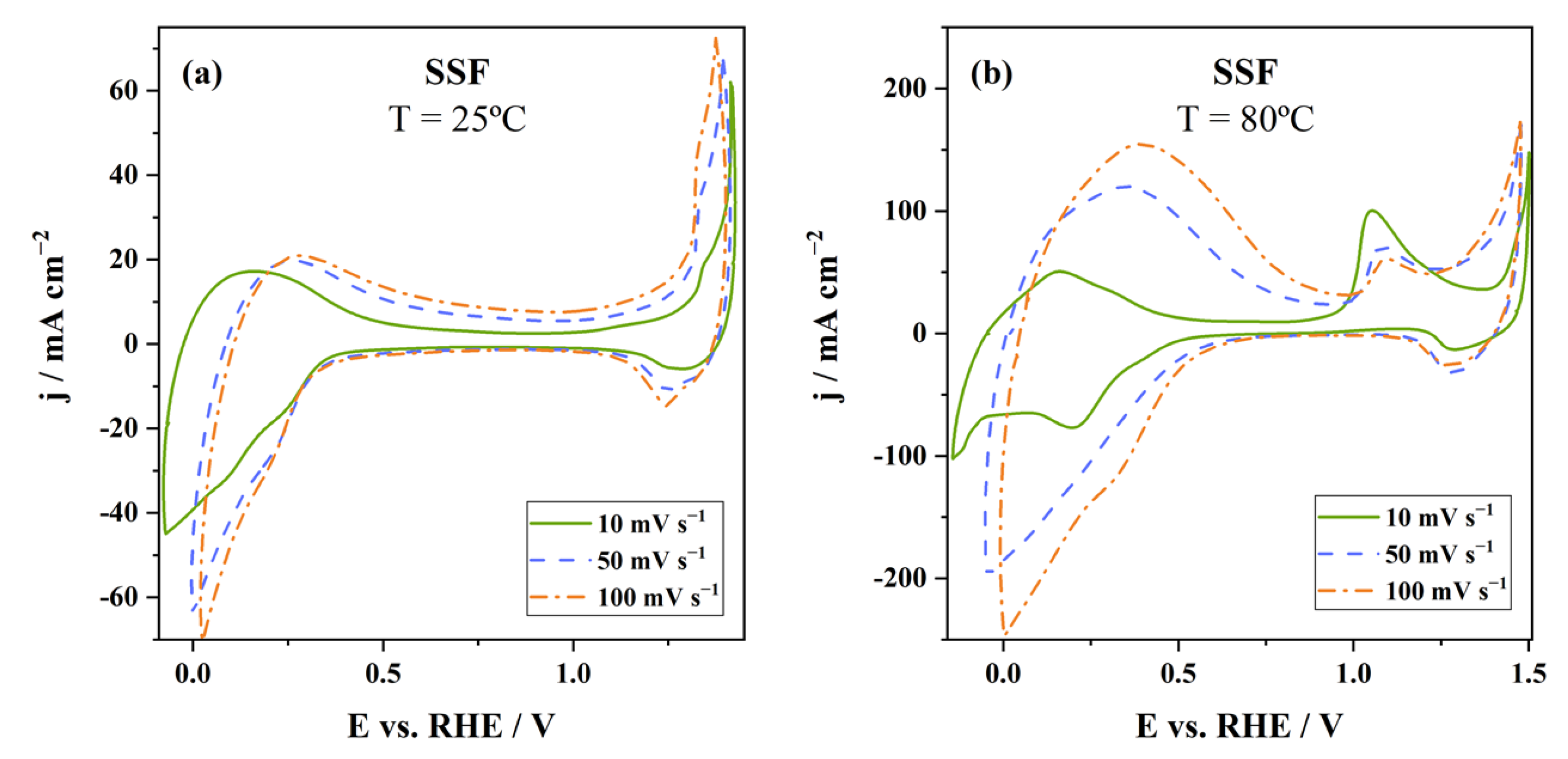
3.1. Characterization of the Redox Behavior of the Electrodes

The cyclic voltammograms recorded at 10, 50, and 100 mV s−1, at 25 °C and 80 °C, are shown in Figure 2, for the NF, and Figure 3, for the SSF. For both metallic foams, the current densities are higher at 80 °C, indicating that the temperature favors the processes.
Concerning the NF, two oxidation peaks are observed in Figure 2, corresponding to the oxidation of Ni to NiOx and Ni(OH)2 and of Ni(OH)2 to NiOOH, as reported in the literature [37]. The corresponding reduction peaks are also well-identified. Hydrogen production starts between −0.20 and −0.15 V at 25 °C and between −0.10 and 0 V at 80 °C, meaning the rise in temperature favors the reaction. Moreover, significantly high current densities were attained in the obtained CVs. This might be explained by the high electrolyte concentration used (10 M NaOH), since higher electrolyte concentrations generally increase conductivity [38]. The potential values where the oxidation and reduction processes occur were slightly different from expected [37]; this might be due to the electrolyte diffusion being more difficult inside a thick, porous network than in denser electrodes.
Concerning the SSF electrochemical behavior, the literature reports the division of the CVs into three regions [39]. The voltammograms presented in Figure 3 clearly show those three well-defined regions. The first region at lower potentials incorporates the first oxidation/reduction related to the iron activity. The next region, at potentials between 0.5 and 1.0 V vs. RHE, is a passivity region. The third region, at higher potentials, is associated with the redox processes of species like Cr, Ni, and Mo. The OER then starts at potentials around 1.35 V and 1.40 V at 25 °C and 80 °C, respectively. As expected, higher potential scan rates lead to higher currents in the recorded CVs. Notably, this effect of scan rate on the iron redox processes (first region, left side) is significantly enhanced at 80 °C, leading to a thicker passivation layer that inhibits the redox processes occurring in the third region (1–1.3 V), which explains the observed opposite trend of those of the first region.

3.2. Study of the HER/OER from the Tafel Analysis
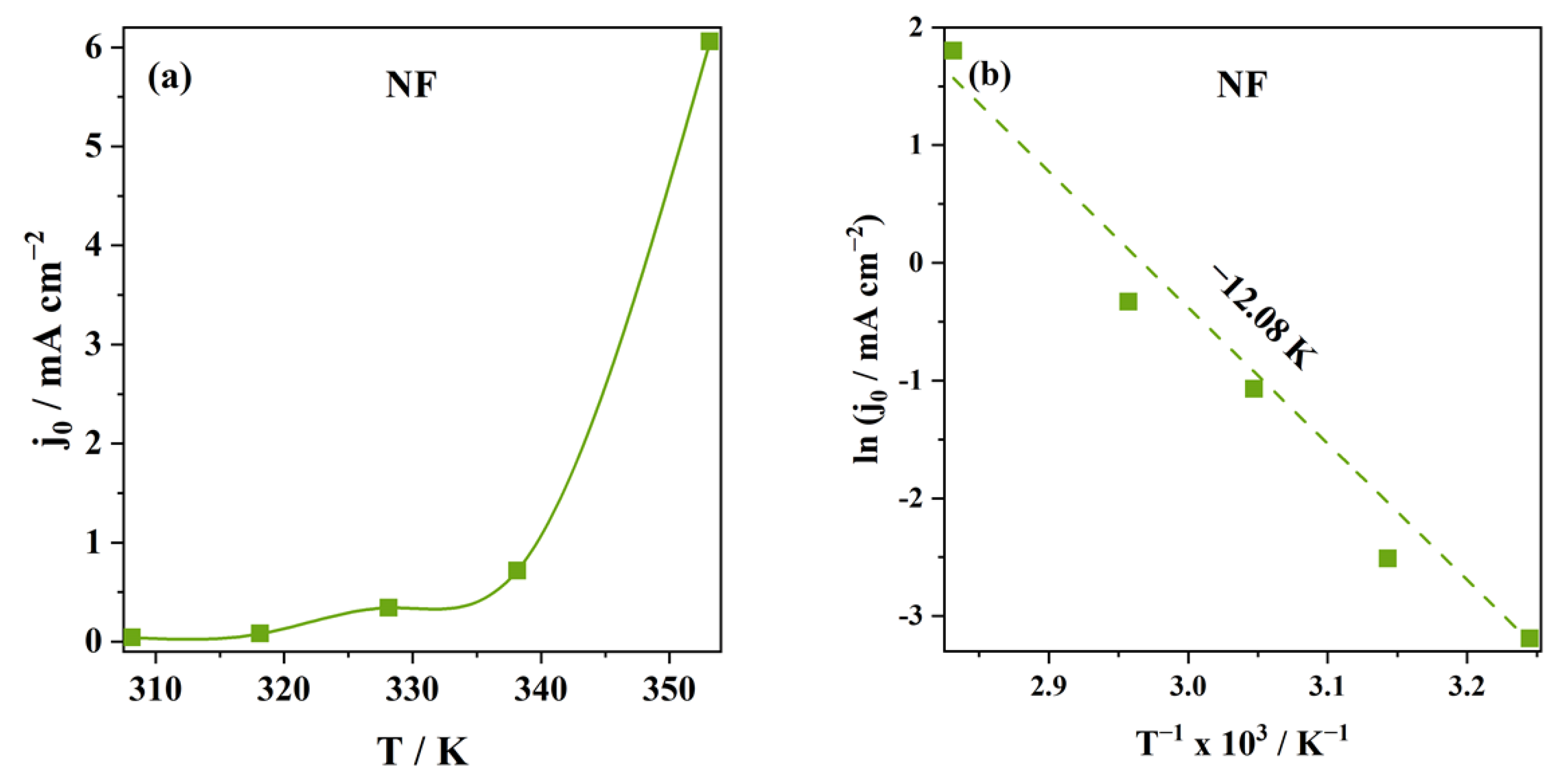
3.2.1. HER

The electrocatalytic activity of the NF towards the HER was evaluated using LSV. Figure 4a displays the polarization curves obtained through scanning the electrode potential from the OCP to −0.25 V vs. RHE at 5 mV s−1 scan rate at different temperatures. The direct observation of the polarization curves demonstrates that the temperature increase favors hydrogen evolution—significantly higher current densities are reached at higher temperatures, and the formation of hydrogen starts at lower potentials.
The corresponding Tafel plots shown in Figure 4b were obtained by adjusting the experimental data to Equation (5). From the Tafel plots, the Tafel slope, b, was obtained directly, and the charge transfer coefficient, α, and exchange current density, j0, were calculated through Equations (6) and (7), respectively,
|η| = a + b log |j|
b = −2.3 RT/nαF
j0 = 10−a/b
where η is the potential difference between the applied potential and the equilibrium potential (0 V vs. RHE for HER), T is the temperature (in K), R is the ideal gas constant (8.314 J mol−1 K−1), n is the number exchanged, and F is Faraday’s constant (96,485 C mol−1) [11].
The onset overpotential, ηonset, i.e., the overpotential required to initiate the reaction, was determined through the intersection of the almost vertical line related to the increase in the current density against the potential (i.e., the Tafel region) with the nearly horizontal line representing current densities close to 0. Table 2 summarizes the parameters calculated from the Tafel analysis shown in Figure 4b.
It is clear from Table 2 that the Tafel slopes increase with the temperature. Usually, this behavior indicates that the temperature rise does not favor the reaction: the higher the Tafel slope, the smaller the current density variation for a more significant potential variation. Nevertheless, the observed increase is not that sharp. This tendency has been observed in previous works, like the one reported by Pierozynski and Mikolajczyk [40], in which the Tafel slopes increased from 137 mV dec−1 at 20 °C to 222 mV dec−1 at 60 °C (Table 3).
From the resulting Tafel slopes, it was possible to conclude that, since their values are superior to 120 mV dec−1, the reaction rate-determining step is either Volmer or Heyrovsky, depending on the surface coverage of the adsorbed hydrogen. No visible modification was observed in the NF surface resulting from the applied potentials and temperatures, suggesting good stability of the NF electrode during these experiments.
Regarding the cathodic charge transfer coefficient, it is observed that as the temperature rises, its value deviates slightly from 0.5. Usually, a transfer coefficient close to 0.5 translates into good reaction reversibility. When it assumes lower values, the oxidation processes are favored, and the energy fraction contributing to hydrogen production is small. This is also a less favorable aspect of the performance of the NF electrode at higher temperatures. Pierozynski and Mikolajczyk also reported this trend [40], with a decrease in the αc value from 0.45 to 0.37 as the temperature increases from 20 °C to 60 °C.
However, the ηonset and j0 values support the statement that the temperature rise enhances the HER, as evident by the decrease in the ηonset and the significant increase in the j0 (Figure 5a). Specifically, at higher temperatures, the low onset overpotential for HER and the high j0 values (cf. Table 2) obtained for the NF are outstanding compared to previous studies (Table 3).
To prove that the temperature favors HER, the activation energy, Ea, was also calculated using the Arrhenius equation, Equation (8) [26]. The relation between the logarithm of j0 with the reciprocal temperature can be seen in Figure 5b.
lnj 0 = lnA i E a RT
The adjustment to the Arrhenius equation was acceptable, with an R2 value of 0.98. The slope from the Arrhenius plot (Figure 5b) led to an Ea of 100 kJ mol−1. The resulting activation energy is higher than that of pure Ni electrodes (51 kJ mol−1 [26]). The high value obtained can be justified by the significant increase in j0 with the temperature, leading to a higher slope.
In conclusion, it can be said that the NF electrode shows an excellent performance towards the HER at all temperatures and that the temperature rise enhances this behavior. The less positive results obtained regarding the cathodic charge transfer coefficient and Tafel slopes are insufficient to refute this statement since the j0 increase with the temperature is outstanding.

3.2.2. OER

Similar to the NF, the SSF was studied towards the OER using LSV. The polarization curves for all the temperatures, presented in Figure 6a, were obtained by varying the potential at 2 mV s−1 from the OCP to 1.65 V. In general, the OER starts at a potential of around 1.48 V. Then, the corresponding Tafel plots in Figure 6b were obtained following the same procedure described for the HER. In the OER case, η is calculated as the difference between the applied potential and the standard electrode potential, 1.23 V. OER kinetic parameters are then determined from Equations (5)–(7), as well as ηonset for OER. The parameters obtained from the Tafel analysis are summarized in Table 4.
Table 4 shows that the Tafel slope decreases by almost 70 mV with the temperature increase, suggesting that higher temperatures favor the OER. Lower values of the Tafel slope translate into a more significant variation in the current density with a small variation in the potential. On the other hand, the ηonset shows a detrimental increase with the temperature. Regarding j0, the values are low and decrease with the temperature. This trend directly stems from the Tafel analysis, as it is influenced by the decrease in the Tafel slope and its low values. Therefore, it cannot be regarded as a sign that temperature does not favor oxygen evolution at the SSF.
Concerning the αa, the values present a substantial increase with the temperature, becoming closer to 1, meaning that the energy fraction contributing to H2 production significantly increases with the temperature. Overall, the temperature rise favors OER despite the j0 decrease with temperature, making it impossible to determine the Ea for this reaction. Table 5 directly compares the results obtained for the herein-studied SSF and other reported SS-based electrodes for OER, showing good agreement with previous studies [23,24,26,43,44,45].

3.3. Stability Tests

The CP technique was utilized to assess the long-term performance of the foams and draw conclusions about their stability. The measurements were conducted at a constant applied current of −50 mA cm−2 for the NF and 50 mA cm2 for the SSF for 16 h at 25 °C. The CP curves obtained for the HER (with NF) and the OER (with SSF) can be seen in Figure 7a and Figure 7b, respectively.
A minor potential variation in the first 5 h can be observed for the NF. Then, it stabilizes at around −0.5 V. Nevertheless, in the 16 h of testing, the potential varies only about 0.02 V, indicating the excellent stability of the electrode. Regarding the SSF, when submitted to the constant current density of 50 mA cm−2, the potential increases by about 0.06 V within the 16 h of the test, stabilizing at a potential close to 1.6 V. These values agree with the ones presented by Hu et al. [23], who performed a similar study with NF and stainless steel mesh (SSM).
The stability tests (Figure 7) also demonstrate that a current density of 50 mA cm−2 can be generated using NF as the cathode and SSF as the anode by applying a cell voltage of ca. 2–2.1 V. This assumption is based on the fact that the NF attains −50 mA cm−2 at a potential of −0.5 V (Figure 7a) and the SSF attains 50 mA cm−2 at a potential between 1.53 and 1.6 V (Figure 7b). Thus, considering the potential difference between the SSF anode and the NF cathode, an electrolyzer operating at 50 mA cm−2 would roughly require a cell voltage of 1.6 V minus −0.5 V, which is 2.1 V.

3.4. Determination of the ECSA

Since the materials are foams, it is important to determine their ECSA. The ECSA represents the area of the electrode material in contact with the electrolyte, where the HER and OER occur. In the case of foam electrodes, this area is not the same as the geometric area. There are several approaches to calculating the ECSA, and in this study, it was determined by cycling the electrodes at different scan rates, from 10 to 100 mV s−1, in a non-Faradaic region and then applying Equations (2) and (3). Figure 8a,c show the CVs of the foams obtained at different scan rates by cycling the electrodes ±50 mV around the OCP. It can be observed that the curves approach the expected rectangular behavior, confirming the existence of the double layer. The Idl was obtained following Equation (3) at a potential of 0.795 V for the NF and 0.885 V for the SSF. The plots of Idl against ν are presented in Figure 8b,d. From the slope of these plots, Cdl values of 1643 µF cm−2 and 253 µF cm−2 were obtained for the NF and the SSM electrodes, respectively. A higher Cdl was expected for the NF, since Zhou et al. [46] reported a value of 3400 µF cm−2. The resulting ECSA values determined by Equation (2) were 820 cm2 and 179 cm2 for the NF and SSF, respectively. The results collected are shown in Table 5.
With the ECSA calculated, it was also possible to obtain the roughness factor, Rf, of the electrodes, by dividing it by the geometric area of the electrodes, Ageometric, as shown in Equation (9). The results are also presented in Table 6.
Rf = ECSA/Ageometric

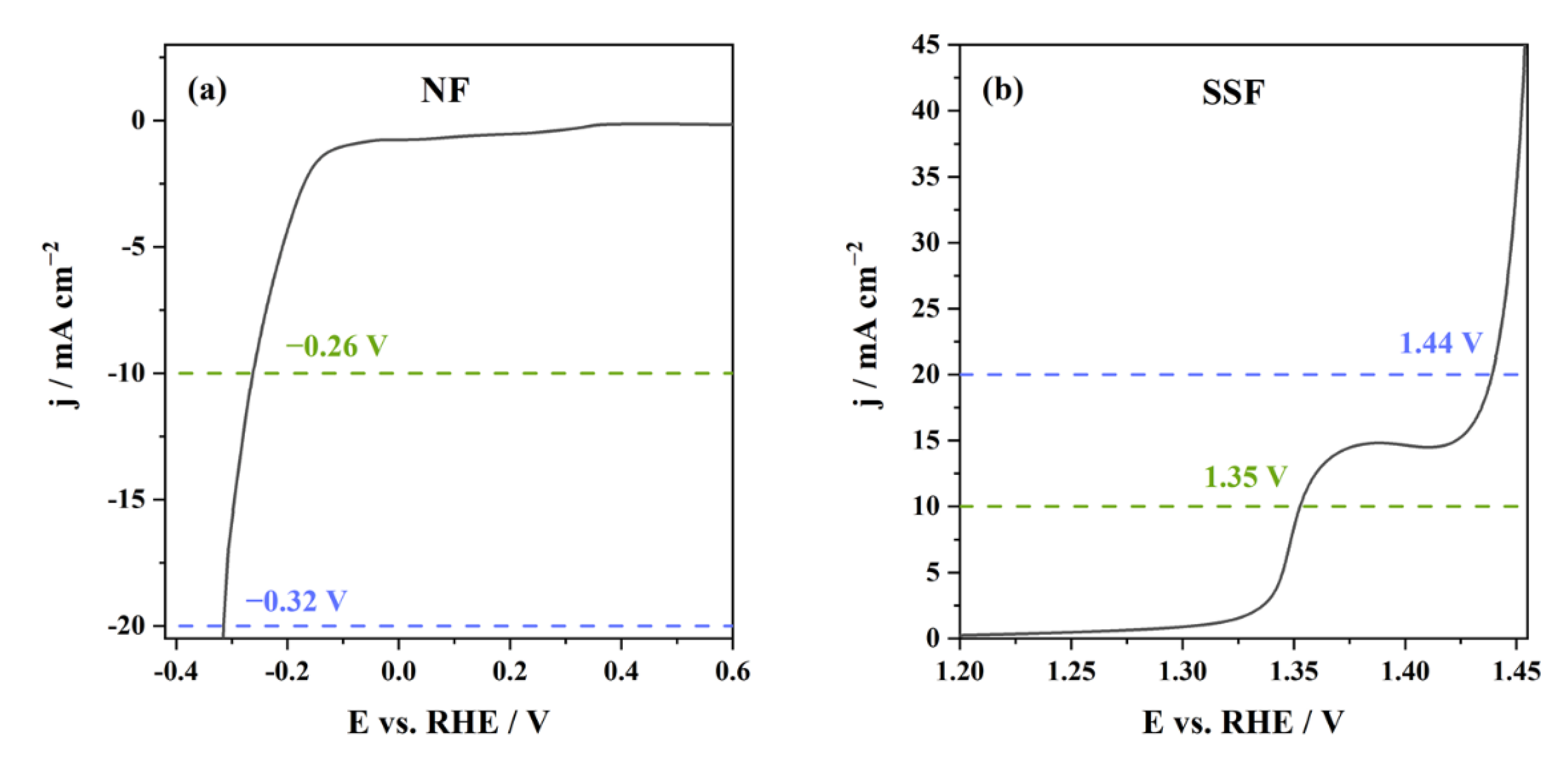
3.5. Overall Water Electrolysis Performance

Based on the positive results obtained for the electrodes’ individual performance, their catalytic activity for the overall water splitting process was further studied in a two-electrode system using NF as the cathode and SSF as the anode. The electrolysis cell polarization curve was recorded from the OCV to 2.0 V at 2 mV s−1 (Figure 9).
These results follow, and even surpass, those reported by Hu et al. [23], who studied the overall water splitting process using NF as the cathode and SS mesh as the anode. The potentials required to generate 10, 20, and 50 mA cm−2 were slightly higher than the ones obtained in this work (Figure 9), specifically 1.74 V, 1.86 V, and 1.93 V.
Additionally, it can be seen that the potentials at 10 and 20 mA cm−2 are slightly lower but still in agreement with the potential differences obtained from the linear scan voltammograms of the individual electrodes (Figure 10), 1.61 V and 1.76 V, respectively. The potential to generate 50 mA cm−2 is even better than the potential difference obtained from the foams’ stability tests. Thus, the present results confirm the steady-state performance of NF and SSF for the HER, OER, and overall water splitting.

4. Conclusions

The path towards future energy systems lies in using green hydrogen, produced by water electrolysis powered by renewable energy sources. Therefore, enhancing the efficiency and market competitiveness of water electrolysis technologies is crucial for a hydrogen economy to thrive and achieve decarbonization targets in 2050.
The proper selection of the electrode materials is, by far, one of the main factors influencing the efficiency of the electrochemical reactions. Therefore, this study confirmed the appropriateness of nickel foam (NF) and stainless steel foam (SSF) as the cathode and anode for a high-efficiency electrolyzer being developed by TecnoVeritas (Portugal). The foams’ catalytic behavior was examined using CV, LSV, and CP in the 25–80 °C range to assess the impact of temperature on their performance.
The individual performance studies revealed that the NF and SSF electrodes exhibited outstanding catalytic behavior towards HER and OER, respectively, particularly at elevated temperatures. Furthermore, they showed stable activity when subjected to a continuous current density of 50 mA cm−2 for 16 h. The high surface area of the foam electrodes appears to be the key factor influencing the efficiency of HER and OER.
Building upon their exceptional individual performance, the behavior of the foams in the overall water electrolysis process was evaluated in a small-scale electrolysis cell. The results surpassed those observed in the individual study of the foams, confirming their consistent performance in HER, OER, and the whole water splitting process.
Hence, the current study confirms the suitability of NF and SSF as the cathode and anode, respectively, for a highly efficient electrolyzer. Furthermore, it can be deduced that the efficiency of the electrolyzer escalates with higher temperatures, such as 80 °C. These results enable TecnoVeritas to progress towards the pilot scale of the project, marking another significant stride towards attaining the goal of carbon neutrality in an economically viable way.

Author Contributions

Conceptualization, J.A. and D.M.F.S.; investigation, A.L.S.; methodology, A.L.S., J.A., and D.M.F.S.; resources, J.A. and D.M.F.S.; supervision, J.A., M.J.C. and D.M.F.S.; validation, J.A., M.J.C., and D.M.F.S.; writing—original draft preparation, A.L.S.; writing—review and editing, M.J.C. and D.M.F.S. All authors have read and agreed to the published version of the manuscript.

Funding

The support of the Foundation for Science and Technology (FCT, Portugal) is gratefully acknowledged for funding a contract in the scope of programmatic funding UIDP/04540/2020 (D.M.F. Santos).

Data Availability Statement

The data presented in this study are available on request from the corresponding author.

Acknowledgments

The authors gratefully acknowledge TecnoVeritas (https://www.tecnoveritas.net, accessed on 19 October 2022) for providing the industrial facilities and for helping in the supervision of A.L. Santos.

Conflicts of Interest

The authors declare no conflict of interest.

References

  1. David, M.; Ocampo-Martínez, C.; Sánchez-Peña, R. Advances in alkaline water electrolyzers: A review. J. Energy Storage 2019, 23, 392–403. [Google Scholar] [CrossRef] [Green Version]
  2. Communication COM/2020/301: A Hydrogen Strategy for a Climate-Neutral Europe. Available online: https://knowledge4policy.ec.europa.eu/publication/communication-com2020301-hydrogen-strategy-climate-neutral-eulrope_en (accessed on 27 May 2021).
  3. Rashid, M.M.; Al Mesfer, M.K.; Naseem, H.; Danish, M. Hydrogen production by water electrolysis: A review of alkaline water electrolysis, PEM water electrolysis and high temperature water electrolysis. Int. J. Eng. Adv. Technol. 2015, 4, 2249–8958. Available online: https://citeseerx.ist.psu.edu/viewdoc/download?doi=10.1.1.673.5912&rep=rep1&type=pdf (accessed on 2 May 2021).
  4. Da Silva Veras, T.; Mozer, T.S.; dos Santos, D.d.C.R.M.; da Silva César, A. Hydrogen: Trends, production and characterization of the main process worldwide. Int. J. Hydrogen Energy 2017, 42, 2018–2033. [Google Scholar] [CrossRef]
  5. IEA: Hydrogen—Tracking Energy Integration. Available online: https://www.iea.org/reports/hydrogen (accessed on 3 August 2021).
  6. IRENA, Hydrogen from Renewable Power: Technology Outlook for the Energy Transition, International Renewable Energy Agency 2018. Available online: https://www.irena.org/publications/2018/Sep/Hydrogen-from-renewable-power (accessed on 10 June 2021).
  7. Nikolaidis, P.; Poullikkas, A. A comparative overview of hydrogen production processes. Renew. Sustain. Energy Rev. 2017, 67, 597–611. [Google Scholar] [CrossRef]
  8. Rezk, H.; Olabi, A.G.; Abdelkareem, M.A.; Alahmer, A.; Sayed, E.T. Maximizing Green Hydrogen Production from Water Electrocatalysis: Modeling and Optimization. J. Mar. Sci. Eng. 2023, 11, 617. [Google Scholar] [CrossRef]
  9. Arcos, J.M.M.; Santos, D.M.F. The hydrogen color spectrum: Techno-economic analysis of the available technologies for hydrogen production. Gases 2023, 3, 25–46. [Google Scholar] [CrossRef]
  10. Ferreira, A.P.R.A.; Oliveira, R.C.P.; Mateus, M.M.; Santos, D.M.F. A review of the use of electrolytic cells for energy and environmental applications. Energies 2023, 16, 1593. [Google Scholar] [CrossRef]
  11. Chatenet, M.; Pollet, B.G.; Dekel, D.R.; Dionigi, F.; Deseure, J.; Millet, P.; Braatz, R.D.; Bazant, M.Z.; Eikerling, M.; Staffell, I.; et al. Water electrolysis: From textbook knowledge to the latest scientific strategies and industrial developments. Chem. Soc. Rev. 2022, 51, 4583–4762. [Google Scholar] [CrossRef]
  12. Schmidt, O.; Gambhir, A.; Staffell, I.; Hawkes, A.; Nelson, J.; Few, S. Future cost and performance of water electrolysis: An expert elicitation study. Int. J. Hydrogen Energy 2017, 42, 30470–30492. [Google Scholar] [CrossRef]
  13. Tang, J.; Xu, X.; Tang, T.; Zhong, Y.; Shao, Z. Perovskite-based electrocatalysts for cost-effective ultrahigh-current-density water splitting in anion exchange membrane electrolyzer cell. Small Methods 2022, 6, 2201099. [Google Scholar] [CrossRef]
  14. Xu, X.; Shao, Z.; Jiang, S.P. High-entropy materials for water electrolysis. Energy Technol. 2022, 10, 2200573. [Google Scholar] [CrossRef]
  15. Sun, H.; Xu, X.; Kim, H.; Jung, W.; Zhou, W.; Shao, Z. Electrochemical water splitting: Bridging the gaps between fundamental research and industrial applications. Energy Environ. Mater. 2023, e12441. [Google Scholar] [CrossRef]
  16. Sengupta, D.; Privitera, S.M.S.; Milazzo, R.G.; Bongiorno, C.; Scalese, S.; Lombardo, S. Ni foam electrode solution impregnated with Ni-FeX(OH)Y catalysts for efficient oxygen evolution reaction in alkaline electrolyzers. RSC Adv. 2020, 10, 25426–25434. [Google Scholar] [CrossRef]
  17. Kjartansdóttir, C.K.; Moller, P. Development of Hydrogen Electrodes for Alkaline Water Electrolysis. Doctoral Thesis, Technical University of Denmark, Lyngby, Denmark, 2014. [Google Scholar]
  18. Pletcher, D.; Li, X. Prospects for alkaline zero gap water electrolysers for hydrogen production. Int. J. Hydrogen Energy 2011, 36, 15089–15104. [Google Scholar] [CrossRef] [Green Version]
  19. Gong, M.; Wang, D.Y.; Chen, C.C.; Hwang, B.J.; Dai, H. A mini review on nickel-based electrocatalysts for alkaline hydrogen evolution reaction. Nano Res. 2016, 9, 28–46. [Google Scholar] [CrossRef]
  20. Santos, A.L.; Cebola, M.-J.; Santos, D.M.F. Towards the hydrogen economy—A review of the parameters that influence the efficiency of alkaline water electrolyzers. Energies 2021, 14, 3193. [Google Scholar] [CrossRef]
  21. Milazzo, R.G.; Privitera, S.M.S.; D’Angelo, D.; Scalese, S.; Di Franco, S.; Maita, F.; Lombardo, S. Spontaneous galvanic displacement of Pt nanostructures on nickel foam: Synthesis, characterization and use for hydrogen evolution reaction. Int. J. Hydrogen Energy 2018, 43, 7903–7910. [Google Scholar] [CrossRef]
  22. Milazzo, R.G.; Privitera, S.M.S.; Scalese, S.; Monforte, F.; Bongiorno, C.; Condorelli, G.G.; Lombardo, S.A. Ultralow loading electroless deposition of IrOx on nickel foam for efficient and stable water oxidation catalysis. Int. J. Hydrogen Energy 2020, 45, 26583–26594. [Google Scholar] [CrossRef]
  23. Hu, X.; Tian, X.; Lin, Y.W.; Wang, Z. Nickel foam and stainless steel mesh as electrocatalysts for hydrogen evolution reaction, oxygen evolution reaction and overall water splitting in alkaline media. RSC Adv. 2019, 9, 31563–31571. [Google Scholar] [CrossRef]
  24. Yu, F.; Li, F.; Sun, L. Stainless steel as an efficient electrocatalyst for water oxidation in alkaline solution. Int. J. Hydrogen Energy 2016, 41, 5230–5233. [Google Scholar] [CrossRef]
  25. Sadaf, S.; Walder, L.; Kuepper, K.; Dinklage, S.; Wollschläger, J.; Schneider, L.; Hardege, J.; Daum, D.; Schäfer, H.; Steinhart, M. Stainless steel made to rust: A robust water-splitting catalyst with benchmark characteristics. Energy Environ. Sci. 2015, 8, 2685–2697. [Google Scholar]
  26. Colli, A.N.; Girault, H.H.; Battistel, A. Non-Precious Electrodes for Practical Alkaline Water Electrolysis. Materials 2019, 12, 1336. [Google Scholar] [CrossRef] [PubMed] [Green Version]
  27. Ekspong, J.; Wågberg. Stainless Steel as A Bi-Functional Electrocatalyst—A Top-Down Approach. Materials 2019, 12, 2128. [Google Scholar] [CrossRef] [PubMed] [Green Version]
  28. Phillips, R.; Dunnill, C.W. Zero gap alkaline electrolysis cell design for renewable energy storage as hydrogen gas. RSC Adv. 2016, 6, 100643–100651. [Google Scholar] [CrossRef] [Green Version]
  29. Tahir, M.; Pan, L.; Idrees, F.; Zhang, X.; Wang, L.; Zou, J.J.; Wang, Z.L. Electrocatalytic oxygen evolution reaction for energy conversion and storage: A comprehensive review. Nano Energy 2017, 37, 136–157. [Google Scholar] [CrossRef]
  30. Sequeira, C.A.C.; Santos, D.M.F.; Šljukić, B.; Amaral, L. Physics of electrolytic gas evolution. Braz. J. Phys. 2013, 43, 199–208. [Google Scholar] [CrossRef] [Green Version]
  31. Bard, A.J.; Faulkner, L.R. Electrochemical Methods: Fundamentals and Applications, 2nd ed.; John Wiley & Sons: New York, NY, USA, 2001. [Google Scholar]
  32. An Electrochemistry Resource for Reference Electrodes, Electrochemical Impedance Instrumentation. Available online: http://www.consultrsr.net/resources/ref/calomelpotl.htm (accessed on 20 May 2021).
  33. Zhang, J.; Wang, T.; Pohl, D.; Rellinghaus, B.; Dong, R.; Liu, S.; Zhuang, X.; Feng, X. Interface engineering of MoS2/Ni3S2 heterostructures for highly enhanced electrochemical overall-water-splitting activity. Angew. Chem. 2016, 128, 6814–6819. [Google Scholar] [CrossRef]
  34. Cossar, E.; Houache, M.S.E.; Zhang, Z.; Baranova, E.A. Comparison of electrochemical active surface area methods for various nickel nanostructures. J. Electroanal. Chem. 2020, 870, 114246. [Google Scholar] [CrossRef]
  35. Ohmic Drop Part 2—Measurements, Metrohm Autolab B.V. Available online: http://www.autolabj.com/appl.files/appl%20note2015/Autolab_Application_Note_EC04.pdf (accessed on 25 January 2023).
  36. Woo, A.L.-W. Conductance Studies of Concentrated Solutions of Sodium Hydroxide and Potassium Hydroxide Electrolytes. Master Thesis, South Dakota State University, Brookings, SD, USA, 1968. Available online: https://openprairie.sdstate.edu/cgi/viewcontent.cgi?article=4547&context=etd (accessed on 3 August 2021).
  37. Hall, D.S. An Electrochemical and Spectroscopic Investigation of Nickel Electrodes in Alkaline Media for Applications in Electrocatalysis. Doctoral Thesis, Cambridge University, Cambridge, UK, 2015. Available online: https://www.researchgate.net/publication/272786543_An_Electrochemical_and_Spectroscopic_Investigation_of_Nickel_Electrodes_in_Alkaline_Media_for_Applications_in_Electro-Catalysis (accessed on 20 May 2021).
  38. Zouhri, K.; Lee, S.-Y. Evaluation and optimization of the alkaline water electrolysis ohmic polarization: Exergy study. Int. J. Hydrogen Energy 2016, 41, 7253–7263. [Google Scholar] [CrossRef]
  39. Díaz, B.; Freire, L.; Montemor, M.F.; Nóvoa, X.R. Oxide film growth by CSV on AISI 316L: A combined electrochemical and analytical characterization. J. Braz. Chem. Soc. 2013, 24, 1246–1258. [Google Scholar] [CrossRef]
  40. Pierozynski, B.; Mikolajczyk, T. On the temperature dependence of hydrogen evolution reaction at nickel foam and Pd-modified nickel foam catalysts. Electrocatalysis 2014, 6, 51–59. [Google Scholar] [CrossRef]
  41. Siwek, K.I.; Eugénio, S.; Santos, D.M.F.; Silva, M.T.; Montemor, M.F. 3D nickel foams with controlled morphologies for hy-drogen evolution reaction in highly alkaline media. Int. J. Hydrogen Energy 2019, 44, 1701–1709. [Google Scholar] [CrossRef]
  42. Jamesh, M.I. Recent progress on earth abundant hydrogen evolution reaction and oxygen evolution reaction bifunctional electrocatalysts for overall water splitting in alkaline media. J. Power Sources 2016, 333, 213–236. [Google Scholar] [CrossRef]
  43. Cardoso, D.S.P.; Amaral, L.; Santos, D.M.F.; Šljukić, B.; Sequeira, C.A.C.; Macciò, D.; Saccone, A. Enhancement of hydrogen evolution in alkaline water electrolysis by using nickel-rare earth alloys. Int. J. Hydrogen Energy 2015, 40, 4295–4302. [Google Scholar] [CrossRef]
  44. Zhang, G.R.; Shen, L.L.; Schmatz, P.; Krois, K.; Etzold, B.J.M. Cathodic activated stainless steel mesh as a highly active electrocatalyst for the oxygen evolution reaction with self-healing possibility. J. Energy Chem. 2020, 49, 153–160. [Google Scholar] [CrossRef]
  45. Tiwari, S.K.; Singh, A.K.-L.; Singh, R.N. Studies on the electrocatalytic properties of some austenitic stainless steels for oxygen evolution in an alkaline medium. J. Electroanal. Chem. Interfacial Electrochem. 1991, 319, 263–274. [Google Scholar] [CrossRef]
  46. Zhou, H.; Fang, Y.; Sun, J.; He, R.; Chen, S.; Chu, C.-W.; Ren, Z. Highly active catalyst derived from a 3D foam of Fe(PO3)2/Ni2P for extremely efficient water oxidation. Proc. Natl. Acad. Sci. USA 2017, 114, 5607–5611. [Google Scholar] [CrossRef]
Figure 1. Experimental setup for studying the performance of (a) NF, (b) SSF, and (c) the two electrodes towards the overall water electrolysis in 10 M NaOH at 25 °C.
Sustainability 15 11011 g001
Figure 2. CVs of the NF in 10 M NaOH at different scan rates at (a) 25 °C and (b) 80 °C.
Sustainability 15 11011 g002
Figure 3. CVs of the SSF in 10 M NaOH at different scan rates at (a) 25 °C and (b) 80 °C.
Sustainability 15 11011 g003
Figure 4. (a) Polarization curves and (b) Tafel plots for the HER at NF electrode at different temperatures.
Sustainability 15 11011 g004
Figure 5. (a) Effect of temperature on j0 and (b) the corresponding Arrhenius plot for the NF.
Sustainability 15 11011 g005
Figure 6. (a) Polarization curves and (b) Tafel plots for the OER at the SSF electrode at different temperatures.
Sustainability 15 11011 g006
Figure 7. CP curves for (a) NF and (b) SSF at a constant current density of −50 mA cm−2 and 50 mA cm−2, respectively, at 25 °C.
Sustainability 15 11011 g007
Figure 8. CVs recorded at 10–100 mV s−1 of (a) NF and (c) SSF and the corresponding average capacitive current as a function of the scan rate for (b) NF and (d) SSF.
Sustainability 15 11011 g008
Figure 9. Polarization curve of a two-electrode system with NF cathode and SSF anode at 25 °C.
Sustainability 15 11011 g009
Figure 10. Polarization curves recorded at 25 °C for (a) NF and (b) SSF.
Sustainability 15 11011 g010
Table 1. Effect of temperature on the conductivity (ĸ) of the 30 wt.% NaOH solution, and the determined electrolyte resistance for the NF and SFF electrodes.
T/°Cĸ/S cm−1 [36]RNF/ΩRSSF/Ω
250.26460.37840.8234
350.35920.27880.6066
450.49920.20060.4364
550.63730.15710.3419
650.80080.12510.2721
800.98450.10170.2213
Table 2. Parameters obtained from Tafel analysis for HER at NF electrode.
T/°C3545556580
b/mV dec−1118128152165225
αc/V0.520.490.410.380.28
j0/mA cm−20.0410.0810.3420.7176.058
R20.9971.001.000.9991.00
ηonset/mV20520019016075
Table 3. Overview of the performance of previously reported Ni-based electrodes (and state-of-the-art Pt/C catalyst) for HER.
ElectrodeElectrolyteT/°Cj/
mA cm−2
ηHER/mVb/
mV dec−1
StabilitySource
NF10 M NaOH35onset205118stable E of ca. −700 mV at −50 mA cm−2 for 16 hthis work
NF10 M NaOH80onset75225-this work
NF1 M KOHRT−10217130stable E of ca. −400 mV at −50 mA cm−2 for 20 h[23]
NF0.1 M NaOH20--137-[40]
NF0.1 M NaOH60--222-[40]
Ni8 M KOHRTonset21098stable j of ca. −17.5 mA cm−2 at −350 mV for ca. 4 h[41]
Aged Ni6 M KOH30−10170--[26]
Aged Ni6 M KOH75−10150--[26]
Ni mesh1 M KOHRT−10275143-[23]
NF@SS38 M KOHRTonset130160stable j of ca. −130 mA cm−2 at −350 mV for ca. 4 h[41]
Pt/C1 M KOHRT−103330-[42]
Table 4. Parameters obtained from Tafel analysis for OER at SS electrode.
T/°C3545556580
b/mV dec−110151444134
αa/V0.300.620.740.790.94
j0/mA cm−21.021 × 10−11.943 × 10−42.263 × 10−55.850 × 10−62.088 × 10⁻⁷
R20.9980.9890.9930.9970.993
ηonset/mV240260270280290
Table 5. Overview of the performance of previously reported SS-based electrodes (and state-of-the-art IrO2 catalyst) for OER.
ElectrodeElectrolyteT/°Cj/
mA cm−2
η O E R / mV b/
mV dec−1
StabilitySource
SSF10 M NaOH35onset230101variation of ca. 60 mV at 50 mA cm−2 for 16 hthis work
SSF10 M NaOH80onset29034-this work
316L SS1 M KOHRT1037030stable ηOER during 25 h and stable j of ca. 17 mA cm−2 at 1.63 V for 25 h[24]
Polished 316L SS6 M KOH3010295--[26]
Polished 316L SS6 M KOH7510260--[26]
Cathodic activated SSM1 M KOHRT1027570roughly stable E of 1.6 V at 10 mA cm−2 for 15 h[43]
SSM1 M KOHRT1027751stable E of 1.6 V at 50 mA cm−2 for 20 h[23]
302 SS1 M KOH256.340033stable E of 1.67 V at 25 mA cm−2 for over 40 h[45]
IrO21 M KOHRT1033076-[44]
Table 6. Double-layer capacitance (Cdl), ECSA, and Rf measured for the foams.
NFSSF
Cdl smooth/µF cm−219 [36]30.1 [24]
Cdl foam/µF16,4005400
Cdl foam/µF cm−216431176
ECSA/cm2863179
Rf8639
Disclaimer/Publisher’s Note: The statements, opinions and data contained in all publications are solely those of the individual author(s) and contributor(s) and not of MDPI and/or the editor(s). MDPI and/or the editor(s) disclaim responsibility for any injury to people or property resulting from any ideas, methods, instructions or products referred to in the content.

