Article

Research on J2 Evolution Law and Control under the Condition of Internal Pressure Relief in Surrounding Rock of Deep Roadway

School of Energy and Mining Engineering, China University of Mining & Technology-Beijing, Beijing 100083, China
*
Author to whom correspondence should be addressed.
Sustainability 2023, 15(13), 10226; https://doi.org/10.3390/su151310226
Submission received: 27 April 2023 / Revised: 19 June 2023 / Accepted: 21 June 2023 / Published: 28 June 2023

Abstract

:
In order to solve the support problem of deep soft crushed coal roadway, a concentrated cavern in a mining station of a mine is taken as the test object. Based on the analysis and summary of the field observation data and the law of rock pressure appearance, a new technology of pressure relief anchoring with the main body of “initiative support + borehole pressure relief” is proposed. This new technology will carry out strong active support in the shallow part of the surrounding rock and excavate a row of low-density large-diameter pressure relief boreholes in the deep coal body of the roadway ribs. The numerical analysis model is established by FLAC3D, and the second invariant of deviatoric stress (J2) is used as the analysis index to elaborate the influence of different borehole parameters on the pressure relief effect of roadway surrounding rock. The results show that different borehole parameters have different effects on roadway pressure relief, that is, borehole depth > borehole length > borehole spacing. After the borehole process is used to relieve the pressure of the surrounding rock, the deformation of the mining roadway side in the subsequent observation process is always controlled within the range of 100 mm, and the shallow surrounding rock support system is effectively protected. The comprehensive control effect is very obvious. Therefore, the field practice proves that the supporting technology can effectively solve the problem of large deformation support of similar roadway surrounding rock.

1. Introduction

With the increasing depletion of shallow coal resources, the depth and scope of coal mining in China are constantly expanding, and the mining center of coal resources in China is gradually shifting to the deep ground [1,2,3,4]. As the deep rock mass has the typical complex occurrence of “high in-situ stress”, “high ground temperature”, and “high karst water pressure” [5,6,7,8,9,10], and because of the impact of the strong disturbance caused by coal mining, roadway damage has increased significantly in terms of duration and scope. This has led to perennial renovation of roadways becoming the norm, seriously affecting the safe and efficient production of coal [11,12,13,14,15,16]. Traditional technology theory has mainly been used to deal with mining shallow coal resources, though it has been unable to explain the continuous high-strength deformation of surrounding rock in deep roadways [17,18,19,20]. For this reason, domestic and foreign scholars have carried out fruitful explorations on the mechanical properties of deep coal [21,22,23,24], the deformation and failure mechanism and characteristics of deep surrounding rock [25,26], and the theory and technology of surrounding rock control [27,28,29] from different disciplines. These explorations provide valuable practical experience for the development and improvement of new theories and technologies for deep mining. In view of the large degree of deformation of surrounding rock in deep roadways, long continuous deformation time, the negative impacts of damage, and other control problems, domestic and foreign scholars have put forward a variety of control theories and technologies for surrounding rock. These include controlling the loose load of excavation rock mass acting on the support body [30], controlling the deformation of surrounding rock [31,32], forming the bearing structure of surrounding rock [33], strengthening the properties of surrounding rock by bolt grouting [34] and relieving pressure inside surrounding rock [35]. Xia [36] determined the evolution rule of the loose circle of roadway surrounding rock by simulating the blasting excavation of deep roadway, which provided a feasible practical and theoretical basis for the support of deep soft crushed roadway. Huang [37] analyzed and summarized the characteristics of “three high and one disturbance" in deep roadway and proposed the theory of the large deformation of surrounding rock rheology and structural instability in deep mining roadway. Xie [38] proposed a comprehensive support technology based on bolt and cable support by analyzing the factors affecting the stability of the surrounding rock-bearing structure of the gob-side roadway, which strengthened the bearing structure of the surrounding rock. Li [39] revealed the failure mechanism of bolt support for the problems of high stress, soft surrounding rock, and support failure in the deep roadway, developed high-strength bolt-grouting technology, and improved the quality of surrounding rock support. Yang [40] took the return air roadway of a mine working face as their research background and verified the feasibility of controlling the surrounding rock by excavating the pressure relief roadway. The above research achievements provide valuable practical experience for surrounding rock control of deep roadways. Aiming at the exploration and research of borehole pressure relief, previous researchers focused on applying multiple rows of high-density large-diameter boreholes to the roadway rib to realize the transfer of high stress in the shallow surrounding rock, but this technology has been mainly used to solve the problem of stress concentration in shallow surrounding rock. The traditional surrounding rock borehole pressure relief theory technology used to solve the problem of deep roadway surrounding rock deformation has the following drawbacks: (1) the application of multi-row high-density boreholes in the roadway will aggravate the degree of fragmentation of the shallow surrounding rock, and the bearing capacity of the surrounding rock will further decline. At this time, the surrounding rock is in a low-stress state, and no pressure relief is needed. (2) Due to the application of an intensive borehole, the supporting structure of the shallow surrounding rock is destroyed, and the shallow supporting system of the surrounding rock is sacrificed in the process of relieving pressure. Therefore, due to the differences in deep mining conditions, strengthening support, surrounding rock modification, and traditional pressure relief technology cannot effectively control the deformation of surrounding rock and maintain the stability of the roadway. Moreover, most of the above results take the single principal stress [41,42] as the research index, especially in the aspect of borehole pressure relief, while the second invariant of deviatoric stress (J2) is not introduced as the evaluation basis. The second invariant of deviatoric stress comprehensively considers the combined action of horizontal stress, vertical stress, and shear stress, which can better present the deformation and failure of surrounding rock.
In view of the serious deterioration of the surrounding rock conditions of the centralized cavern and the failure of the support system, the mine adopted a series of high strength surrounding rock reinforcement techniques, such as strong bolts, cable support systems, and grouting, to improve the mechanical properties of the surrounding rock. The control effect on the surrounding rock was not qualitatively improved, but the number of roadway renovations was relatively reduced. With the continuous mining of the working face, the cavern will be destroyed to a greater extent under the dual influence of high stress and strong mining. In order to effectively solve the problem of the deformation of surrounding rock and improve the damage to roadway, this paper proposes a new pressure relief anchoring technology with “initiative support + borehole pressure relief” as the main body, which is compared with the traditional pressure relief technology with dense borehole as shown in Figure 1. The core of this technology is to excavate a row of low-density large-diameter pressure-relief boreholes in the deep coal of the two ribs of the roadway. This is to ensure that effective space is provided for the high-stress transfer of the two ribs of the roadway without destroying the shallow strong anchoring surrounding rock structure. In this paper, the second invariant of deviatoric stress (J2) [43,44,45,46] is used to analyze the stress evolution law of surrounding rock under different borehole parameters. The field engineering practice verifies the practicability of the pressure relief technology, and the research results provide an important scientific basis for improving the surrounding rock control of similar roadways. The research idea of this paper is shown in Figure 2.

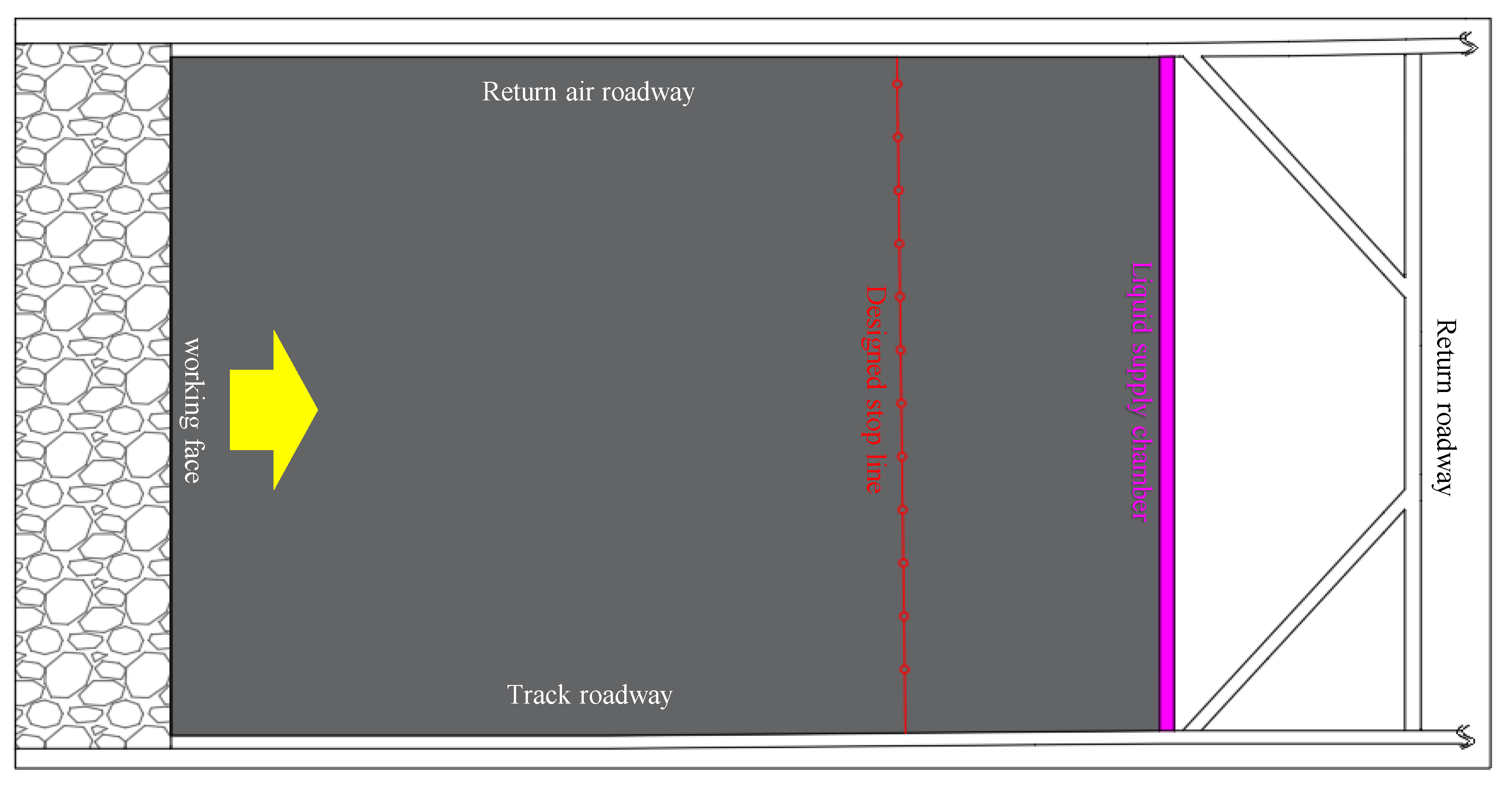
2. Engineering Situation

2.1. Engineering Geological Conditions

The buried depth of the test coal seam is 675 m, and the average coal thickness is 3.0 m. The centralized cavern in a mining section is a rectangle with a width of 5.0 m × a height of 3.0 m. The coal structure in which the cavern is located is complex and the fracture development is clear. The centralized cavern in a mining section is shown in Figure 3.

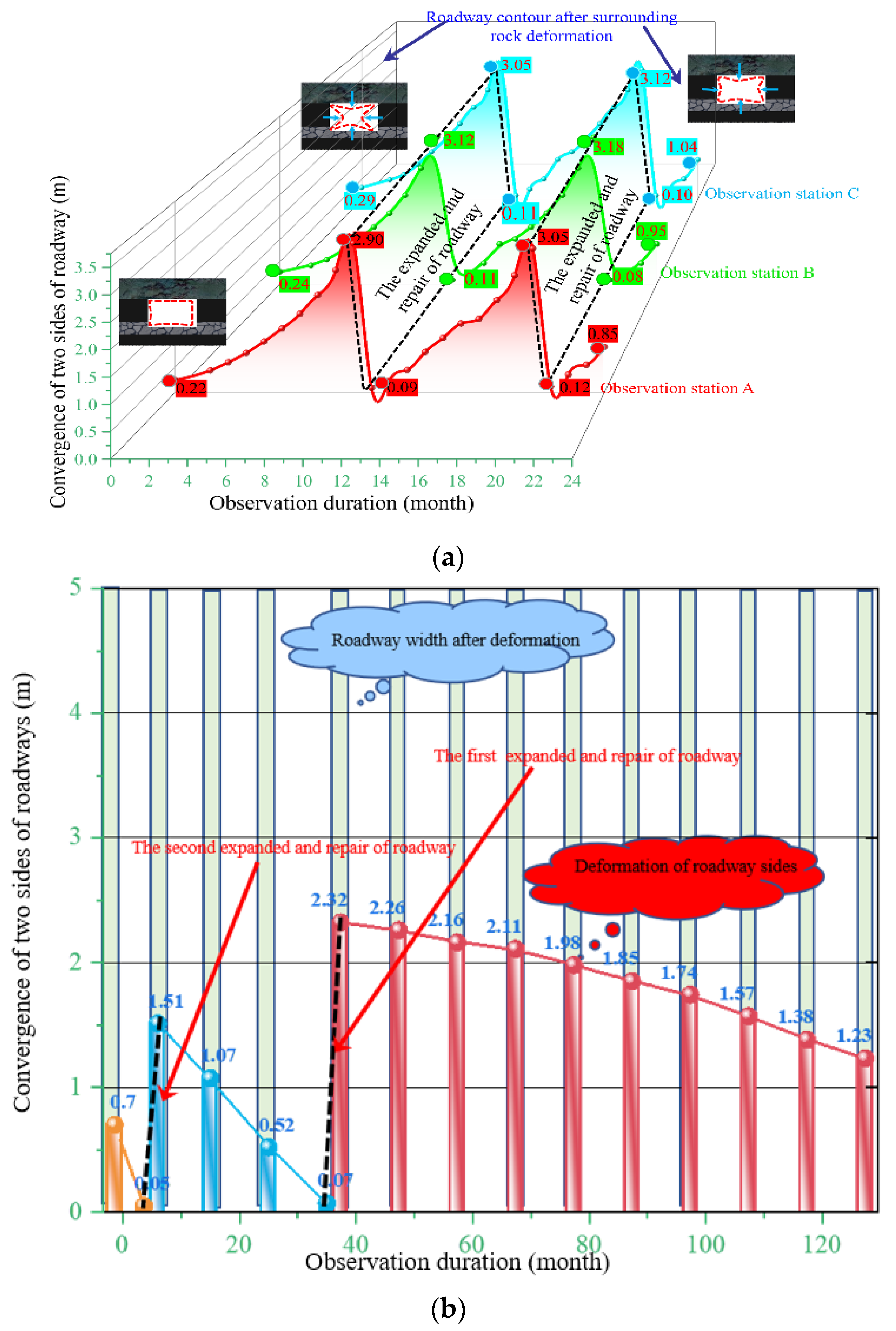
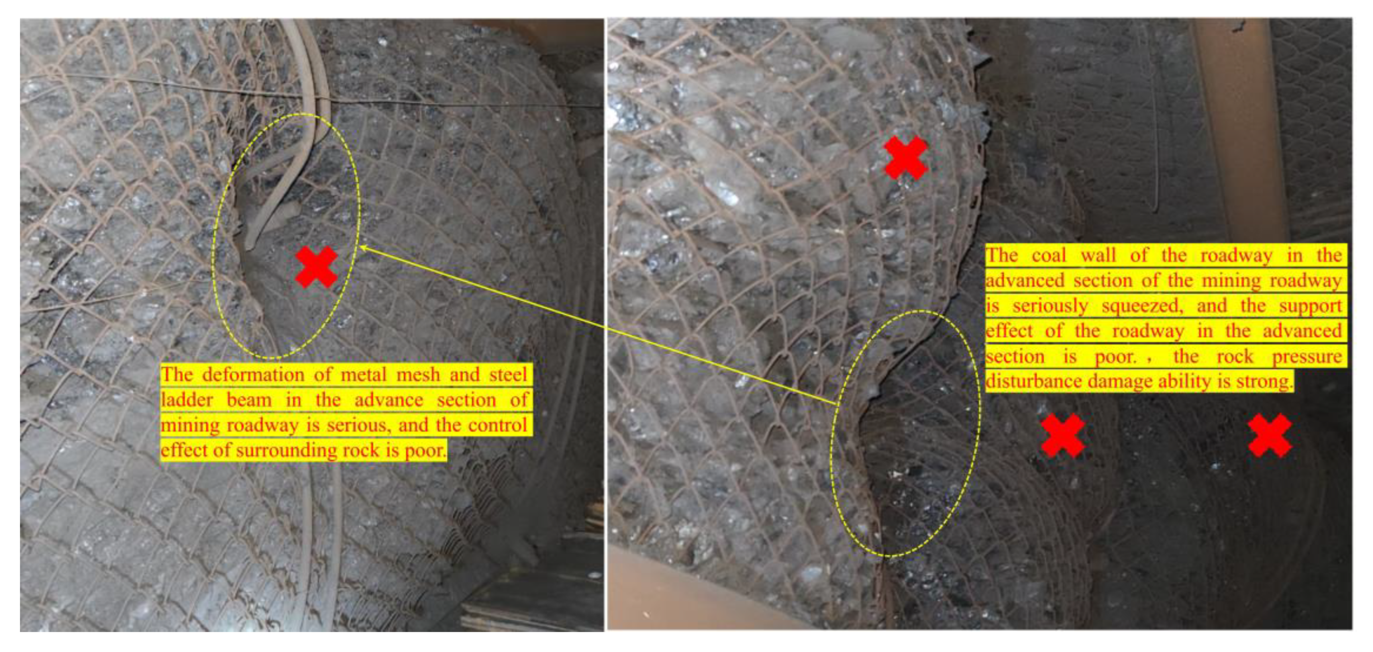
2.2. Characteristics of Mine Pressure in Surrounding Rock of Test Cavern

In order to ensure the normal operation of the mining work, the centralized cavern in a mining section, as shown in Figure 4a, must be repaired every year. This undoubtedly increases the redundant workload and greatly reduces the efficiency of safe mining. The results of the surrounding rock movement of the transportation roadway in the working face, as seen in Figure 4b, show that the surrounding rock movement of roadway in the range of 120 m in front of the working face is more than 1.0 m. The surrounding rock support failure diagram of the mining roadway in the advanced section of the working face is shown in Figure 5. It can be seen that, under the influence of mining in this working face, the mine pressure behavior of the roadway in the advanced section of the working face is very severe, and that the mine pressure disturbance damage ability is strong.
In summary, it is concluded that, when the working face is mined to the designed stop line, the centralized cavern in a mining section will be affected by the severe mining of the working face and that a wider range of damage will then occur. At this time, the cavern is seriously damaged and cannot meet the needs of mining production.

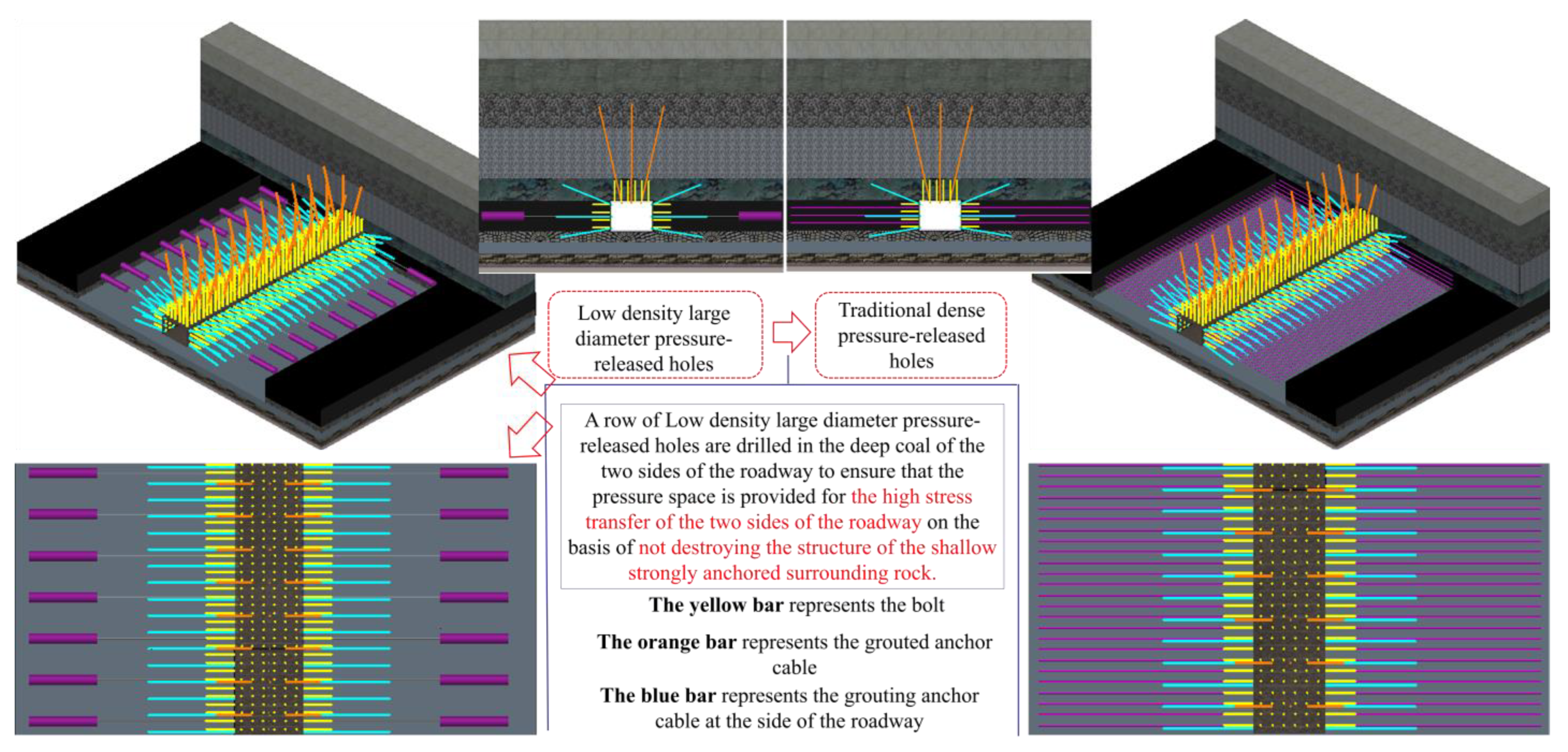
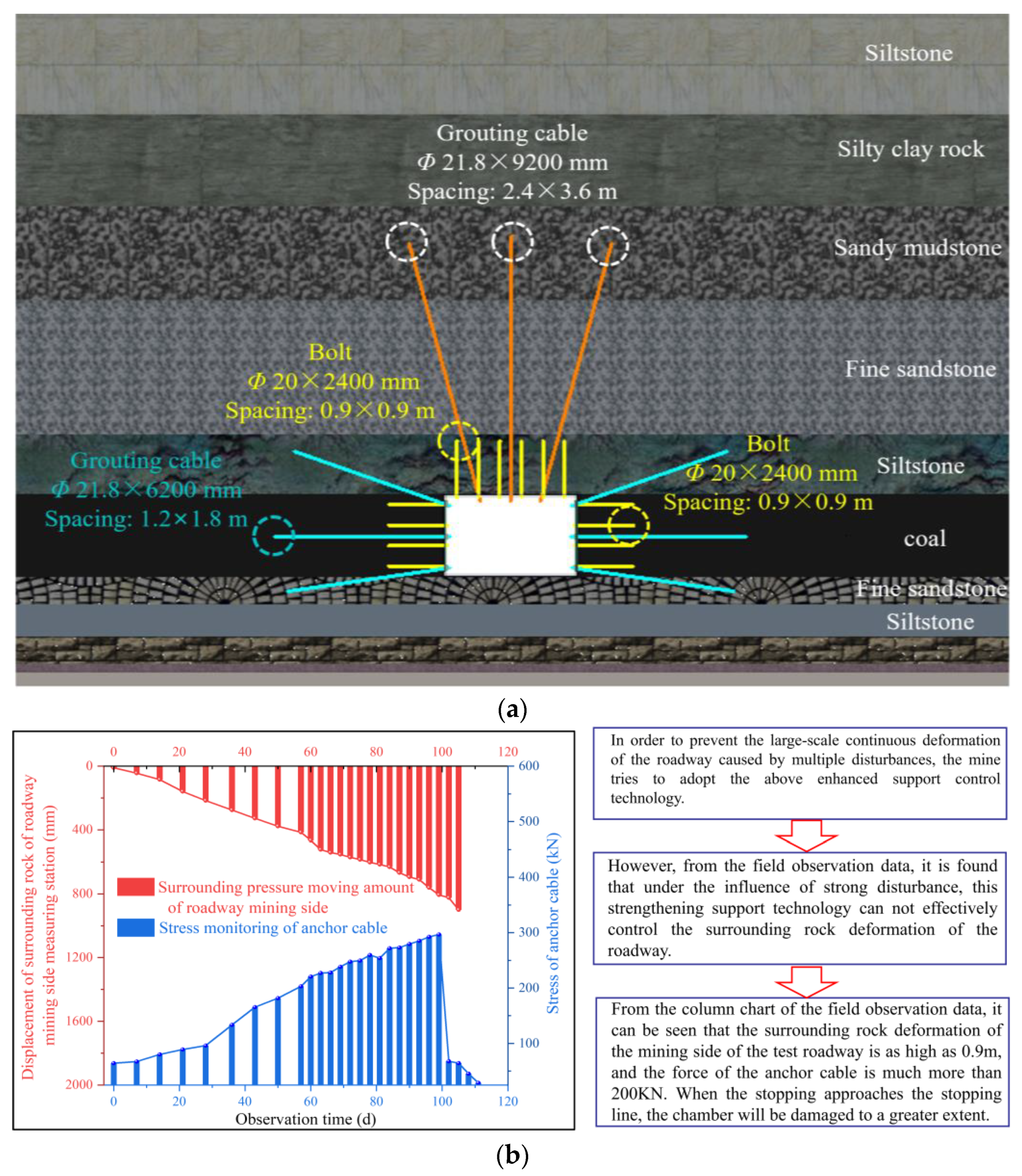
2.3. Problems Existing in The Test Cavern after Strengthening Support and Surrounding Rock Modification Technology

In view of the phenomenon wherein the continuous, large deformation of the surrounding rock of the test cavern must be regularly expanded and renovated, the roof of the cavern in Figure 6a adopts a grouting anchor cable group with Φ 21.8 × 9200 mm and a row spacing of 2.4 × 3.6 m. The two ribs adopt the comprehensive control technology of a grouting anchor cable with Φ 21.8 × 6200 mm and a spacing of 1.2 × 1.8 m. The above control technology was adopted in the field for the displacement of the surrounding rock of the chamber mining side; the observation results of the bolt (cable) and the field deformation are shown in Figure 6b.
It can be seen from Figure 6 that the continuous deformation of the roadway surrounding rock cannot be effectively improved by strengthening support and surrounding rock modification technology. With the continuous mining of the working face near the stop line, the centralized cavern in a mining section will not be able to withstand the strong mining influence of the working face, which in turn will lead to a wider range of deformation and failure. Therefore, the continuous deformation of the roadway cannot be controlled by control technology for the surrounding rock that comprises, in the traditional process, strengthening supports and modifications to surrounding rock. In this paper, effective measures are taken to control the deformation of surrounding rock by improving the stress state of surrounding rock, so as to ensure that the test cavern meets the needs of efficient and safe mining in the working face.

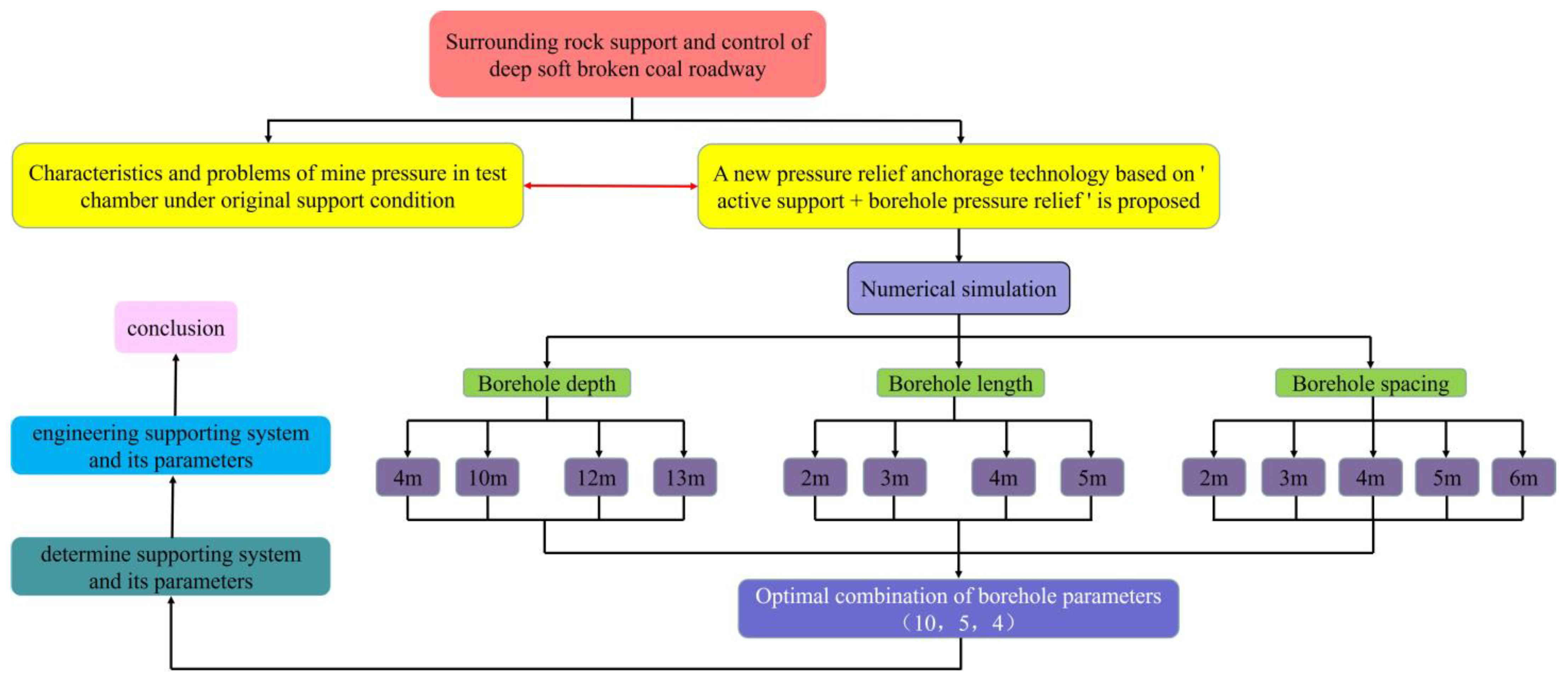
3. Determination of Key Parameters of Borehole Pressure Relief Model

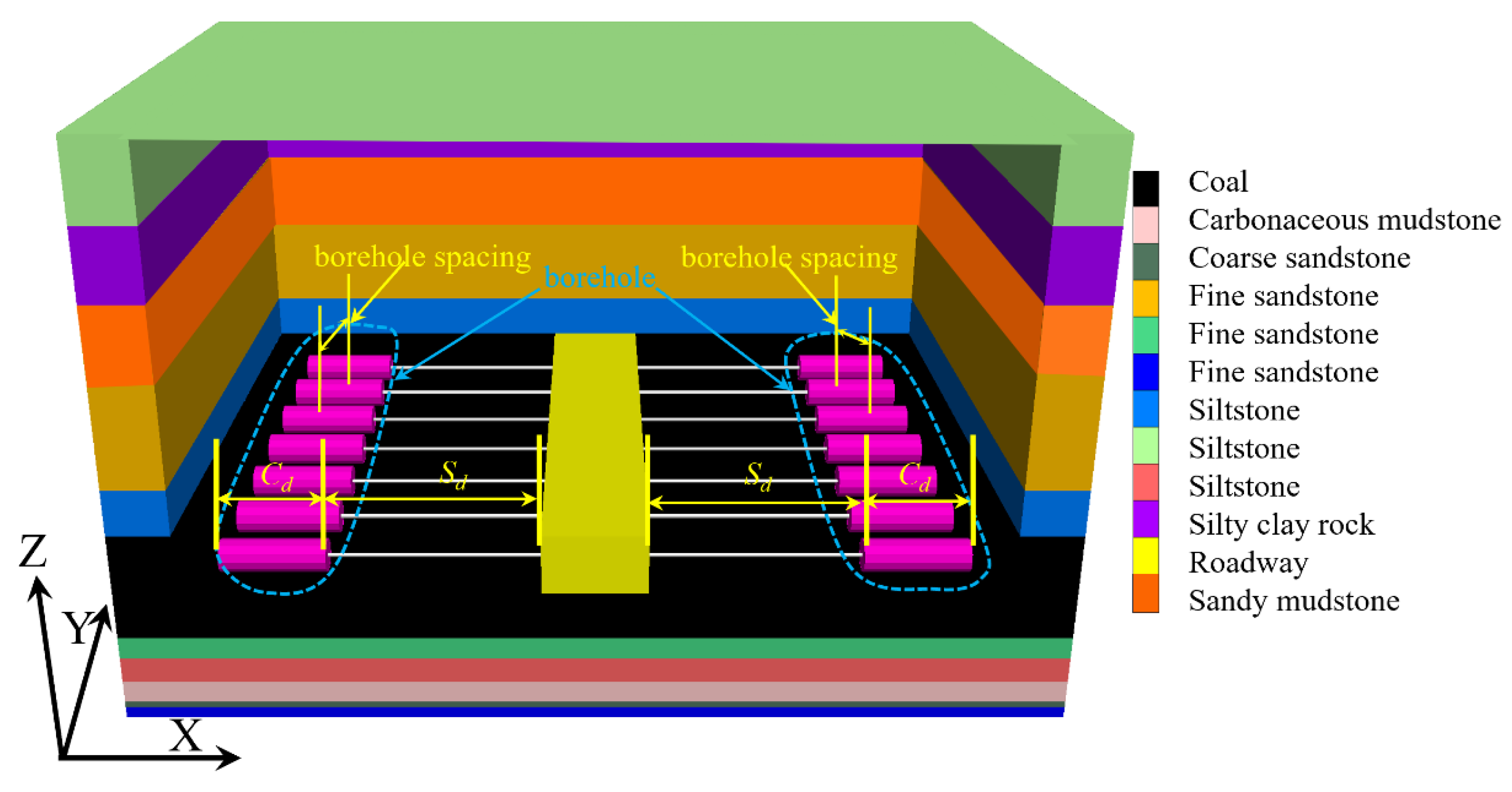
3.1. Numerical Calculation Model

In order to analyze the distribution and evolution law of the second invariant (J2) of the deviatoric stress of the surrounding rock of the roadway under different borehole parameters more vividly and deeply, and to provide more reliable guidance for determining the appropriate borehole parameters (borehole depth, borehole length, borehole spacing) on-site, the FLAC3D numerical software was used to construct a numerical model of the pumping station cavern in the mining area, according to the field engineering geological data and conditions and as shown in Figure 7.
The model uses the Mohr–Coulomb yield criterion to constrain the horizontal displacement of the left and right boundaries in the x direction, the front and rear boundaries in the y direction, and the bottom boundary in the z direction. The vertical displacement in the z direction of the bottom boundary of the model is constrained, the top boundary of the model is constrained by stress, and the lateral pressure coefficient is 1.25.

3.2. The Second Invariant of Deviatoric Stress (J2) Is Used as The Basis for Evaluating the Effect of Pressure Relief

In order to better reveal the essence of the deformation and failure of the surrounding rock of the cavern, this paper uses the deviatoric stress theory in elastoplastic mechanics as the analysis basis, and the plastic deformation is mainly determined by the deviatoric stress tensor invariant.
In elastoplastic mechanics, the stress tensor is usually divided into two parts. Some of these are spherical stress tensors or hydrostatic stress tensors, while the other part is the deviatoric stress tensor. The stress tensor can therefore be expressed by the following formula [47]:
σ i j = σ x τ xy τ xz τ yx σ y τ yz τ zx τ zy σ z = s ij   +   σ m δ ij δ i j = 0 , i j 1 , i = j ,   σ m = 1 3 ( σ x + σ y + σ z )
where a spherical tensor is the stress tensor component; δ i j is the Kronecker symbol; and s i j is the skew component of the stress tensor.
The invariant of the deviatoric stress tensor can be derived as
J 2 = 1 2 S i j S j i = 1 2 ( S 1 2 + S 2 2 + S 3 2 ) = 1 6 [ ( σ 1 σ 2 ) 2 + ( σ 2 σ 1 ) 2 + ( σ 3 σ 1 ) 2 = 1 6 [ ( σ x σ y ) 2 + ( σ y σ z ) 2 + ( σ z σ x ) 2 + 6 ( τ x y 2 + τ y z 2 + τ z x 2 ) ]
where S1, S2, S3 represent the components of the partial stress tensor.
In summary, the second invariant of deviatoric stress (J2) is not only irrelevant to the selection of coordinate system but also takes into account the damaging effect of normal stress and shear stress on rock mass. Therefore, the second invariant of deviatoric stress (J2) is selected to measure the plastic deformation of the surrounding rock. Compared with the single principal stress, J2 can accurately reflect the essence of the deformation of the surrounding rock mass.

3.3. Evaluation Index of Borehole Pressure Relief Effect and Classification of Pressure Relief Degree

The aim of borehole pressure relief technology in deep coal roadway is to transfer the high J2 area of the two ribs of the coal roadway to the deep surrounding rock of the borehole and improve the stress state of the surrounding rock surface. This is undertaken on the basis of maintaining the shallow anchoring, so as to realize the pressure relief protection of the surrounding rock of the continuous large deformation roadway. Once the borehole operation is completed, the J2 distribution in the coal rib will have an internal and external asymmetric “double hump” stress area, hereinafter referred to as the “asymmetric bimodal distribution”. The typical stress adjustment curve is shown in Figure 8.
The direct evaluation index of the deviatoric stress relief effect: di/do (the ratio of internal deviatoric stress peak to the original deviatoric stress peak), Sd-K(do) (the distance from the borehole position to the original deviatoric stress peak position), K(di)-K(do) (the distance from the peak position of internal deviatoric stress to the peak position of original deviatoric stress), de/do (the ratio of external deviatoric stress peak to original deviatoric stress peak), ∇(de) (the increasing range of the peak value of external eccentric stress), K(de)-K(do) (the distance from the peak position of the external deviatoric stress to the peak position of the original deviatoric stress), ∇ [K(de)-K(do)] (the transfer amplitude of the peak position of external deviatoric stress). This paper comprehensively evaluates the transfer effect of high stress around the roadway by analyzing the variation law of the above evaluation indexes under the parameters of borehole depth (Sd) and borehole length (Cd) and the pressure relief degree under the parameter of borehole spacing.

3.4. Determination of Key Borehole Parameters

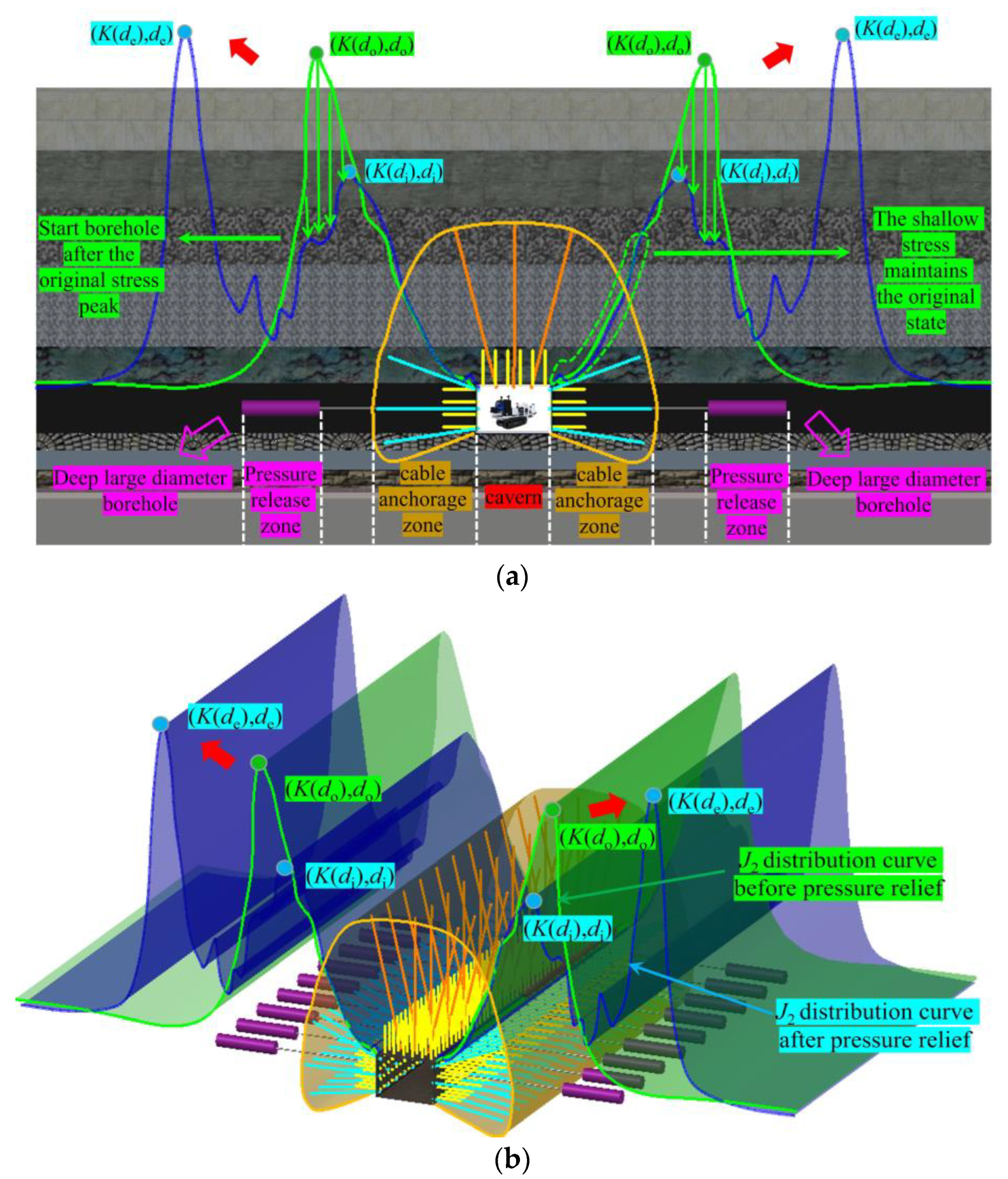
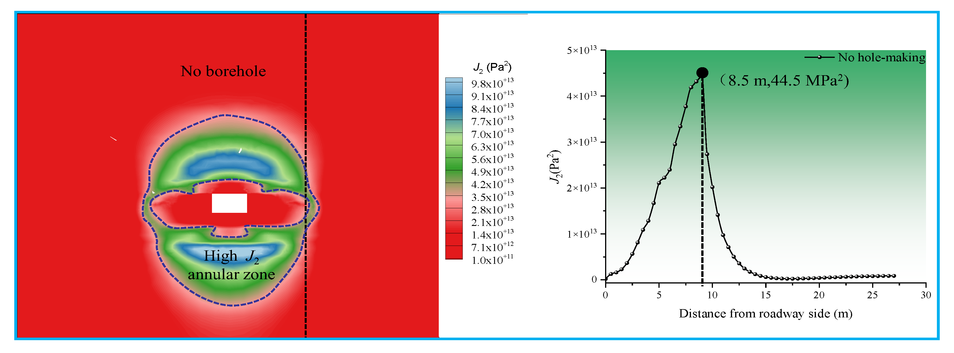
3.4.1. Distribution of J2 in the Surrounding Rock of the Cavern before the Borehole

The distribution of J2 in the surrounding rock of the cavern before the borehole, but after the excavation of the centralized cavern in a mining section, is shown in Figure 9.
Under the condition of no borehole pressure relief, the roof and floor of the surrounding rock of the cavern and the two ribs form a high J2 annular zone, and the J2 peak of the two ribs of the roadway reaches 44.5 MPa2. When the working face advances to the final mining line, the J2 peak value of the surrounding rock of the cavern will be higher than 44.5 MPa2, and the cavern will also be damaged to a greater extent, which is not enough to meet the needs of working face mining.
Therefore, this paper puts forward the surrounding rock control technology of cavern borehole pressure relief. Then, the effect of different borehole parameters on the pressure relief of surrounding rock is analyzed, and the best borehole pressure relief scheme is determined.
The distribution of J2 in the surrounding rock of the cavern under different borehole depths, after the two ribs of the centralized cavern in a mining section have been excavated, is shown in Figure 10.

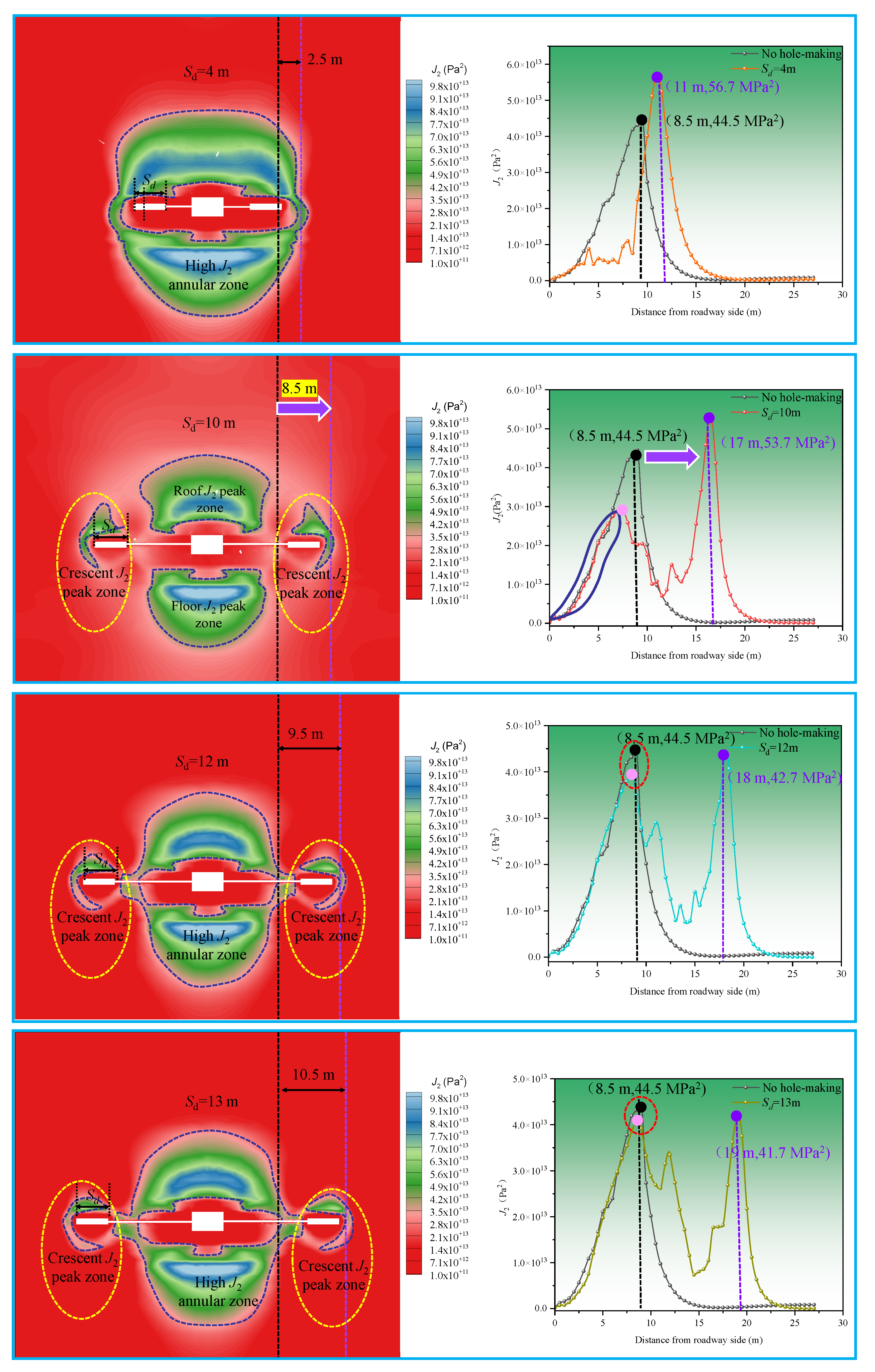
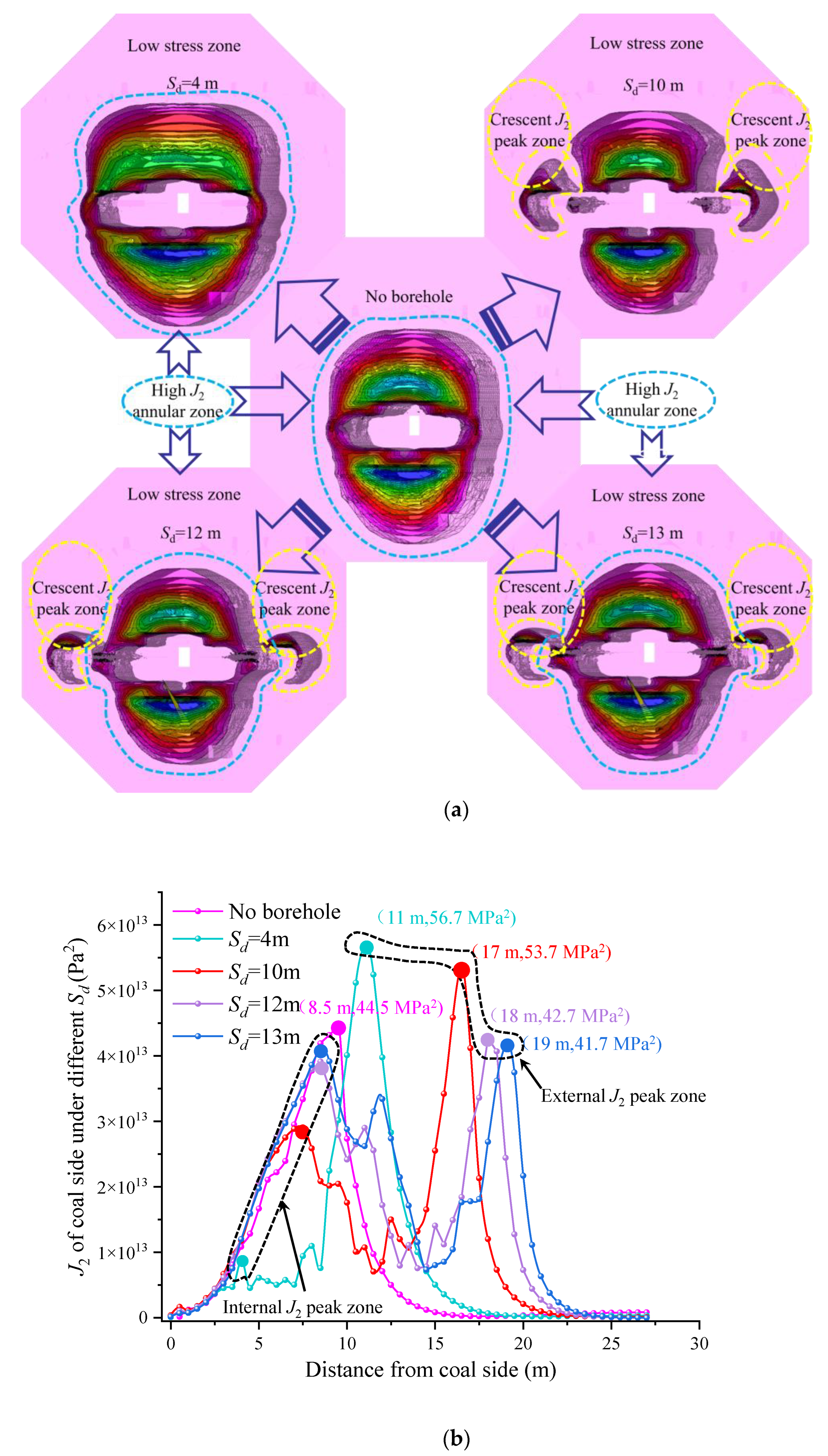
3.4.2. Determination of Borehole Depth

Through the line chart in Figure 10, it can be seen that, under different borehole depths, the J2 of the surrounding rock of the cavern will appear in two asymmetric double peak areas inside and outside, but that the change of the borehole depth will cause the J2 value of the surrounding rock of the roadway to continuously adjust. The distribution characteristics of the surrounding rock J2 under different borehole depths can be summarized as follows:
(1)
Due to the excavation of boreholes in deep coal, the surrounding rock J2 is redistributed. It can be seen from the line chart that, with the increase of borehole depth, the size and peak position of the inner peak (near the roadway rib) continue to approach the peak value of the undrilled stress. On the contrary, the size of the outer peak gradually decreases, while the peak position has a tendency to shift to a deeper position than the original peak.
(2)
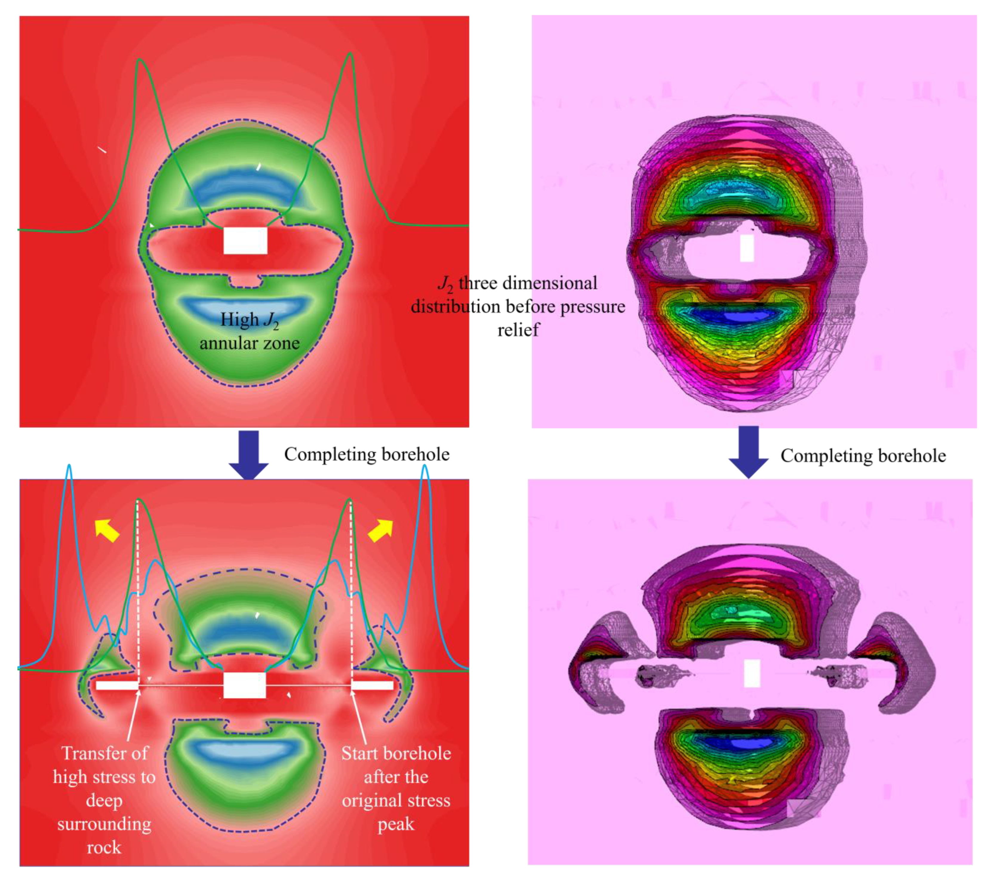
When the borehole depth is 4 m, the peak value of the outer J2 is 56.7 MPa2, and the peak position is only 2.5 m away from the original position. There is still a high J2 annular zone around the roadway, and the range of high J2 is basically consistent with that without a borehole. Even after the borehole, the peak value of J2 in the roadway rib is higher than that without the borehole, and the high J2 peak zone has a poor transfer effect to the deep surrounding rock. This shows that the borehole depth of 4 m is ineffective for surrounding rock pressure relief.
(3)
When the borehole depth is 10 m, the internal J2 peak is 29.1 MPa2, and the external J2 peak is 53.7 MPa2. Compared with the cases with no borehole and with borehole depth of 4 m, there is no longer a high J2 annular zone, and the influence range of the high J2 peak zone is greatly reduced. When the depth of the borehole is 10 m, and the peak position of J2 is transferred to the deep part of the surrounding rock by 8.5 m, the peak area of J2 outside the two ribs of the roadway has been effectively transferred to the deep surrounding rock of the borehole, and the original anchoring effect of the shallow part of the roadway is protected. This realizes the effective pressure relief of the surrounding rock of the roadway.
(4)
When the borehole depth is 12 m, the high J2 annular zone appears again around the roadway surrounding rock. The peak value of internal J2 is 39.1 MPa2, which is only 5.4 MPa2 lower than the original J2 peak value. The peak value of external J2 is 42.7 MPa2. The two ribs of the roadway form a double peak high J2 zone. The existence of double J2 peaks in the surrounding rock of the chamber is likely to cause secondary damage to the rock mass of the roadway. The borehole depth of 12 m is not conducive to the internal pressure relief of the surrounding rock.
(5)
When the borehole depth is 13 m, a larger range of high J2 annular zone appears around the surrounding rock of the roadway, and the range of the annular zone is similar to that of the non-borehole. The peak value of the inner J2 is 40.9 MPa2, which is only 3.6 MPa2 lower than the original J2 peak value, and the peak value of the outer J2 is 41.7 MPa2. The two ribs of the roadway will form a double peak high J2 zone larger than the 12 m range of the borehole. Therefore, a borehole according to this parameter can easily lead to a larger range of secondary damage to the surrounding rock mass and cannot protect the shallow support system of the roadway. A borehole depth of 13 m is more unfavorable to the internal pressure relief of the surrounding rock.
In order to determine the appropriate borehole depth more intuitively, the J2 contour cloud diagram in Figure 11a, stress distribution curve in Figure 11b, and pressure relief evaluation index in Table 1 under different borehole depths are summarized as follows:

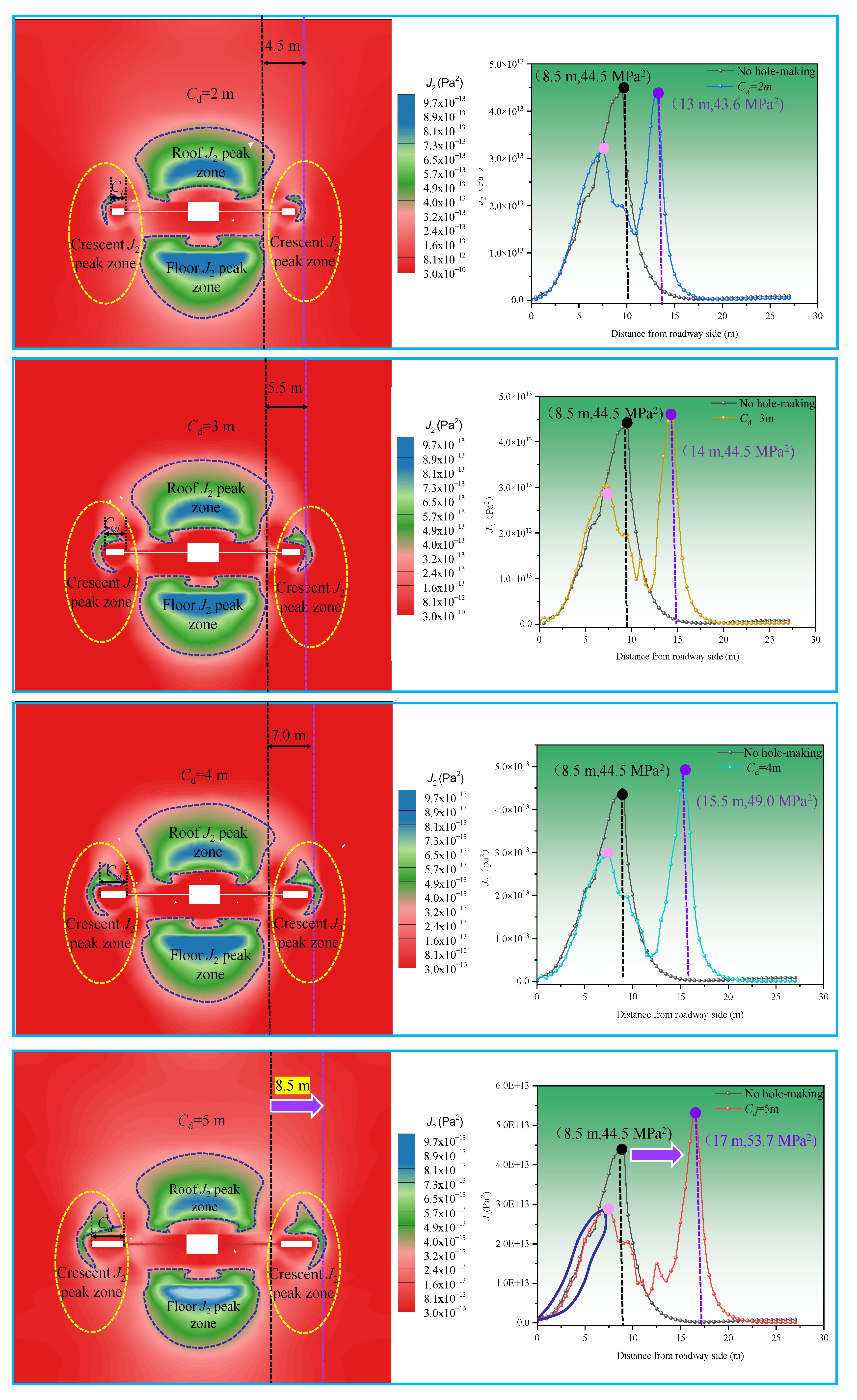
3.4.3. Determination of Borehole Length

The distribution of J2 in the surrounding rock of the cavern under different borehole lengths, after the two ribs of the centralized cavern in a mining section have been excavated, is shown in Figure 12.
It can be seen from the broken line diagram of Figure 12 that, under different borehole lengths, there are also two asymmetric double peak areas in the surrounding rock J2 of the cavern, but that the change of the borehole length causes the J2 value of the surrounding rock of the roadway to be continuously adjusted. The distribution characteristics of the surrounding rock J2 under different borehole lengths can be summarized as follows:
(1)
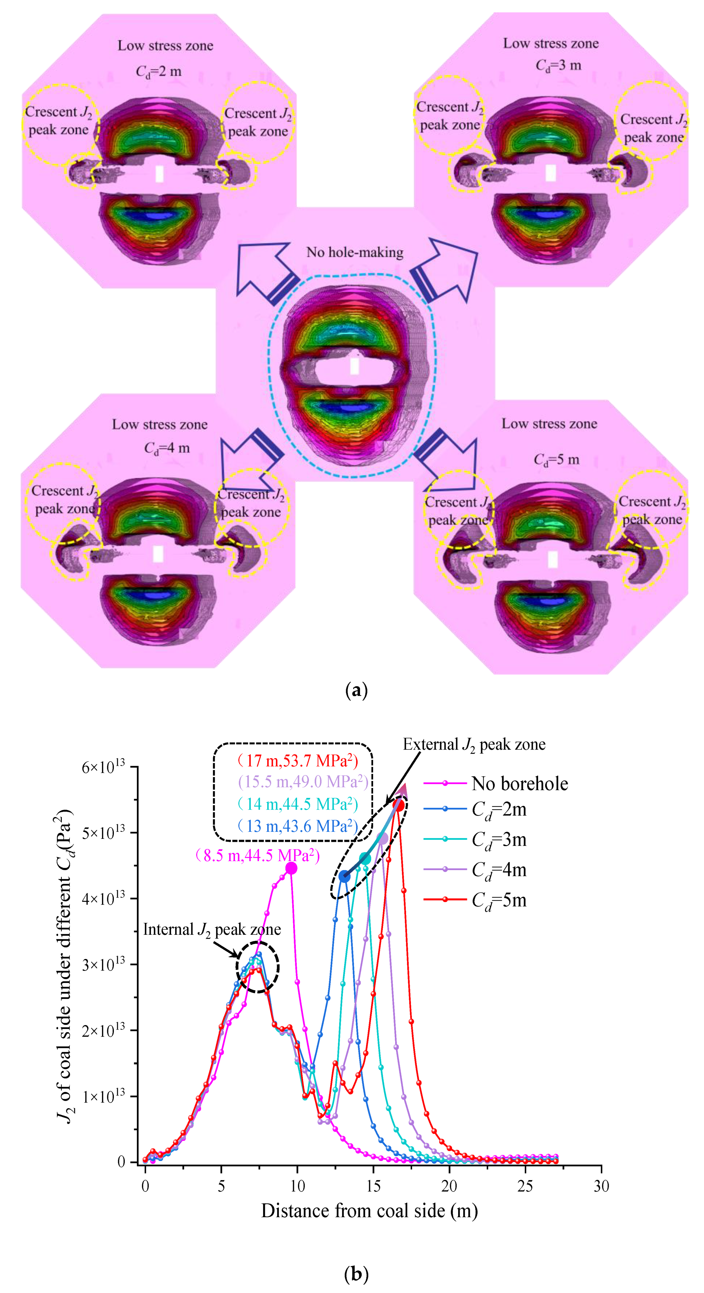
The adjustment of borehole length will not change the shape and value of J2 in the deep surrounding rock after borehole operation. The peak value of outer J2 increases and the effect of deep transfer to surrounding rock is obvious.
(2)
The change of borehole length does not cause significant changes in the peak value of internal J2, but has a certain influence on the peak value and position of external J2 as well as on the distribution range of crescent J2 peak area in the figure.
(3)
When the borehole length is 2 m, 3 m, 4 m, or 5 m, the peak value of external J2 is 43.6 MPa2, 44.5 MPa2, 49.0 MPa2, and 53.7 MPa2, respectively. It can be seen that the change in borehole length has a certain influence on the growth of external J2 peak value, 2 m → 3 m (2.06%), 3 m → 4 m (10.11%), 4 m → 5 m (9.59%).
(4)
With the increase of borehole length, the peak value of outer J2 has a tendency to transfer to the deep part of the surrounding rock. Compared with the peak position of J2 without borehole, the peak position of J2 with borehole lengths of 2 m, 3 m, 4 m, and 5 m is transferred to the deep part by 4.5 m, 5.5 m, 7 m, and 8.5 m, respectively. Compared with the change range of the J2 value, the transfer range of the J2 position is larger, 2 m → 3 m (22.22%), 3 m → 4 m (27.27%), 4 m → 5 m (21.43%).
In order to determine the appropriate borehole length more intuitively, the J2 contour cloud diagram in Figure 13a, stress distribution curve in Figure 13b, and pressure relief evaluation index Table 2 under different borehole lengths are summarized as follows:

3.4.4. Determination of Borehole Spacing

The distribution of J2 in the surrounding rock of the cavern under different borehole spacing conditions, after digging pressure relief holes in the two ribs of the centralized cavern in a mining section, is shown in Figure 14.
It can be seen from Figure 14 that, under the premise of selecting the appropriate borehole depth and borehole length, the appropriate borehole spacing can release the high stress around the borehole and avoid the stress concentration between the holes. The distribution characteristics of surrounding rock J2 under different borehole spacings can be summarized as follows:
(1)
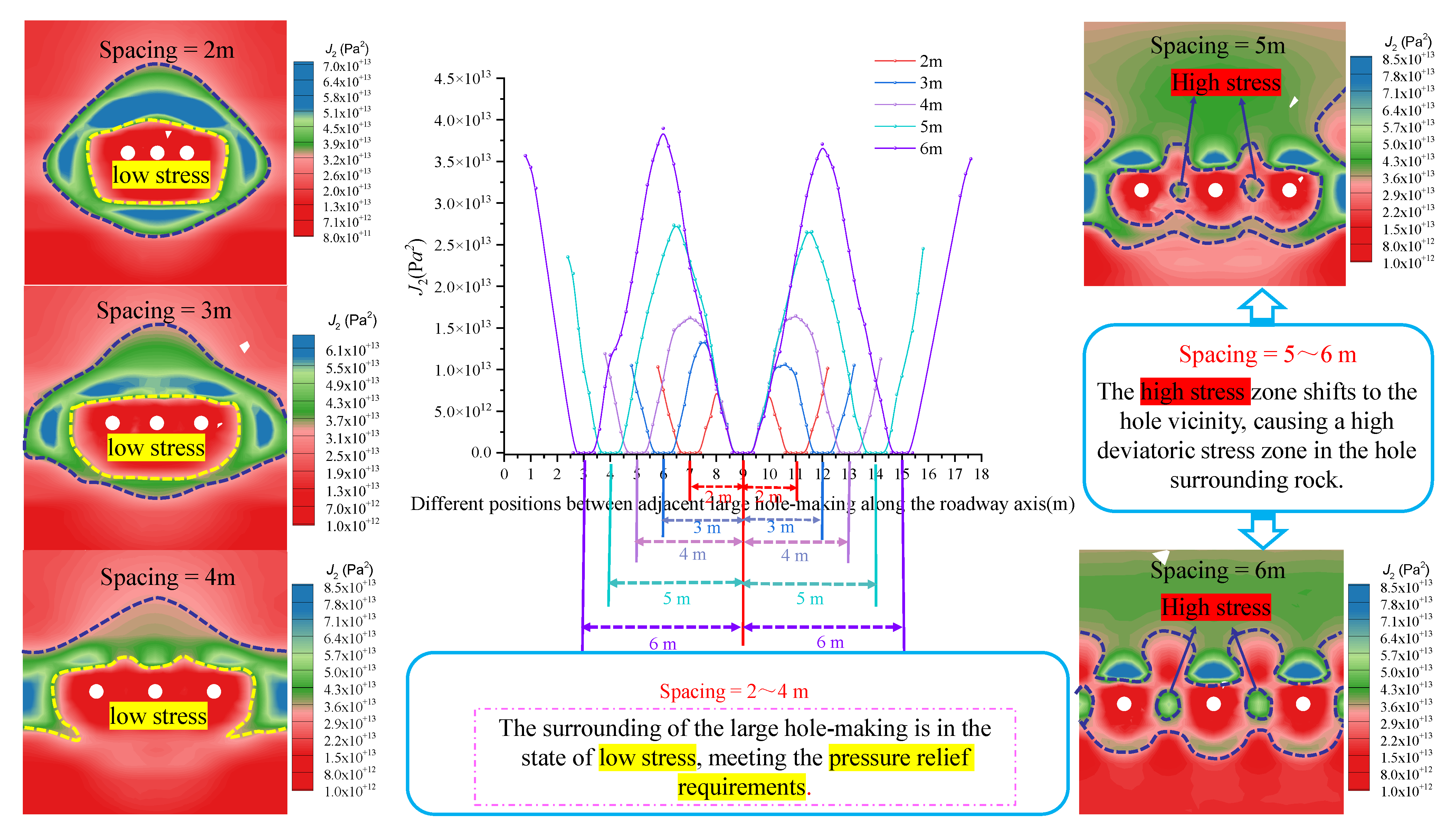
Through the analysis of the stress curve in Figure 13, it can be concluded that, although the borehole spacing is different, the peak value of J2 along the axial direction of the cavern always appears near the middle of the two boreholes, and with the increase of the borehole spacing, the peak value of J2 gradually increases, and the influence range of the high J2 peak zone between the pressure relief holes increases.
(2)
Combined with the analysis of the stress cloud diagram of Figure 14, when the borehole spacing is 5~6 m, a stress concentration occurs in the surrounding rock between adjacent boreholes. This clearly shows that the high stress is transferred to the vicinity of the borehole due to the excessive selection of the borehole spacing, which is not conducive to the release of high stress between adjacent boreholes.
(3)
When the borehole spacing is 2 m, 3 m, and 4 m, the maximum J2 values of the adjacent borehole space rock mass are 10.1 MPa2, 10.5 MPa2, and 12.4 MPa2, respectively. Due to the small borehole spacing, the stress concentration phenomenon no longer occurs around the borehole, thus demonstrating the realization of the pressure relief work of the high-stress transfer to the deep surrounding rock in the direction of the borehole profile. Finally, considering the construction progress and economic benefits, the borehole spacing should not be too small.
In summary, by analyzing and comparing the distribution, evolution, and pressure relief effect of surrounding rock J2 under different borehole parameters, it is concluded that different borehole parameters have different pressure relief effects on the roadway, that is, borehole depth > borehole length > borehole spacing. According to the basic geological conditions of the test cavern, and taking into account the construction progress of the on-site hydraulic punching, a suitable borehole parameter scheme was designed comprising a borehole depth of Sd = 10 m, length of Cd = 5 m, and spacing of 4 m. The adjustment of J2 before and after the borehole of the surrounding rock of the cavern, under these borehole parameters, is shown in Figure 15.

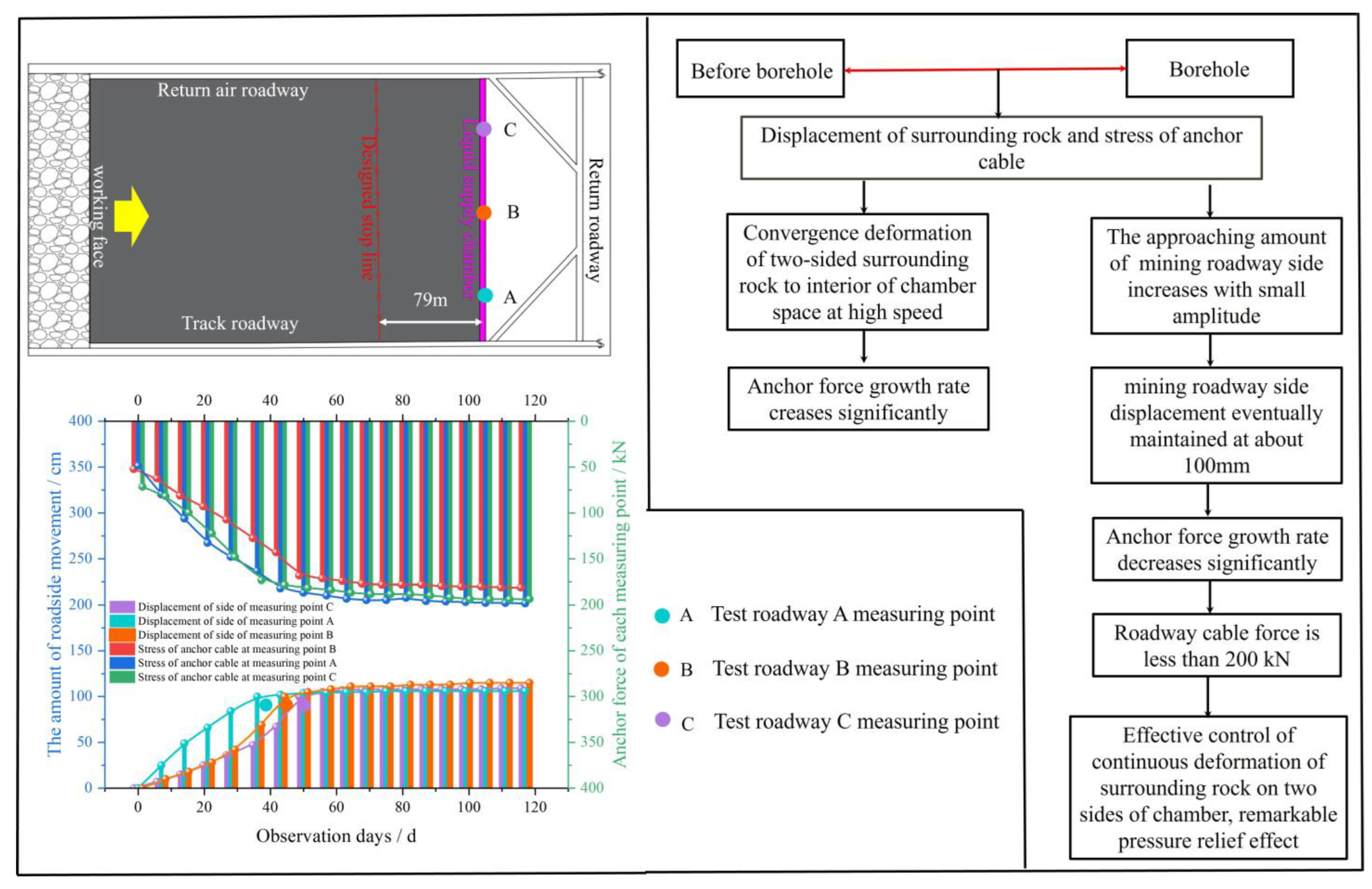
4. Engineering Application

By analyzing the results of field observation data and the characteristics of mine pressure behavior, a new pressure relief anchoring technology is proposed—“initiative support + borehole pressure relief”—as the main body of strong active support in the shallow part of the surrounding rock and the excavation of a row of low-density large-diameter pressure relief boreholes in the deep coal body of the two ribs of the roadway. The comprehensive control technology scheme and control effect of the roadway surrounding rock is shown in Figure 16.
Observation of surrounding rock data
The displacement of surrounding rock and the stress of anchor cable before and after the pressure relief of the centralized cavern were observed and counted. The field observation effect is shown in Figure 17.
From the variation curve of the surrounding rock movement of the mining roadway side of the cavern before and after borehole pressure relief, shown in in Figure 17 (the actual borehole time of each station is marked in the figure), it can be seen that, by comparing the approaching amount of the surrounding rock of the mining roadway side before and after borehole pressure relief, the surrounding rock of the mining roadway side before borehole converges and deforms to the chamber space at a faster speed. When the mining roadway side adopts internal pressure relief measures, the displacement of the mining roadway side increases by a small margin and the displacement of the mining roadway side is finally maintained at about 100 mm. After the internal pressure relief of the mining roadway side of the cavern, the stress growth rate of the anchor cable is clearly reduced. At this time, the stress of the anchor cable on the roadway rib is less than 200 kN, and it is within the reasonable range of the anchor cable. Once the borehole operation had become stable, the deformation of the surrounding rock of the test cavern was well controlled, the support system did not undergo significant damage and deformation, and the field achieved ideal results.
It can be seen that the borehole pressure relief technology realizes the transfer of high stress to the deep part of the surrounding rock without destroying the shallow anchoring ability of the surrounding rock, effectively controlling the continuous deformation of the surrounding rock on both ribs of the cavern, and that the pressure relief effect is remarkable.

5. Conclusions

The continuous deformation of the surrounding rock of the roadway cannot be effectively improved, even after a series of high-strength reinforcement technologies for surrounding rock, such as strong anchor cable support system and grouting, are implemented in the cavern of a mine’s concentrative pumping station to improve the mechanical properties of the surrounding rock. Seeking to improve the stress state of the surrounding rock, this paper proposes a row of low-density, large-diameter, pressure relief boreholes in the deep coal body of the two ribs of the roadway. On the basis of maintaining the strong anchoring of the surrounding rock structure in the shallow part, a new pressure relief anchoring technology with “initiative support + borehole pressure relief” as its main body is provided to provide compensation space for the high-stress transfer of the two ribs of the roadway. The field construction test proves that the pressure relief effect of this technology is good. The test results provide a new way for studying the large deformation and failure of surrounding rock in similarly deep roadways and have important engineering reference significance. The conclusions are summarized as follows:
(1)
By analyzing and comparing the distribution, evolution, and pressure relief effect of surrounding rock J2 under different borehole parameters, it is concluded that different borehole parameters have different effects on the pressure relief effect of a roadway, which is simply summarized as borehole depth > borehole length > borehole spacing. When the borehole depth increases from 4 m to 13 m, the peak value of J2 (near the roadway rib) gradually increases but is smaller than the peak value of J2 without the borehole, and the peak value of J2 shifts to the deep part of the surrounding rock with the increase of borehole depth. When the depth of the borehole is 10 m, the peak position of J2 is transferred to the deep part of the surrounding rock by 8.5 m, which not only protects the original anchoring effect in the shallow part of the roadway but also effectively transfers the peak zone of J2 outside the two ribs of the roadway to the deep surrounding rock of the borehole. This realizes the effective pressure relief of the surrounding rock of the roadway.
(2)
The J2 peak value (di) and its position relationship are related to the borehole depth. The adjustment of borehole length will not change the J2 shape, position, and numerical value within 10 m of the roadway after drilling. The peak value of outer J2 has increased, and the effect of transferring to the deep part of the surrounding rock is obvious. Therefore, the buffer compensation space can be provided for the high J2 transmission and the surrounding rock deformation by reasonably increasing the borehole length.
(3)
On the basis of selecting the appropriate borehole depth and borehole length, the appropriate borehole spacing can release the high stress of surrounding rock and avoid the stress concentration between holes. When the borehole spacing is greater than 5 m, due to the excessive selection of borehole spacing, the higher stress is transferred to the vicinity of the borehole, which is not conducive to the release of high stress between adjacent boreholes. When the borehole spacing is less than 4 m, the borehole spacing is small, and the stress concentration phenomenon no longer occurs around the borehole, thus realizing the pressure relief work of the high-stress transfer to the deep surrounding rock in the direction of the borehole profile. However, considering the economic factors, the borehole spacing should not be too small.
(4)
At present, from the perspective of on-site borehole construction progress, borehole equipment seriously restricts borehole efficiency and affects the normal operation of on-site mining work. Therefore, we need to develop more advanced and efficient borehole equipment to meet borehole needs and coordinate on-site construction progress more efficiently. In addition, due to the different borehole conditions under special geological conditions, we will continue to extend the borehole pressure relief technology to different geological conditions in the future to further improve the borehole pressure relief system.

Author Contributions

Conceptualization, D.C. and S.X.; Methodology, D.C., Z.W. and Z.J.; Validation, D.C. and S.X.; Formal analysis, D.C. and Z.W.; Investigation, Z.L., Q.Y. and J.Z.; Data curation, D.C. and Z.W.; Writing—original draft preparation: D.C., Z.W. and Z.J.; Writing—review and editing: D.C.; Visualization, Z.L., Q.Y. and J.Z.; Supervision, D.C. Project administration, D.C. and S.X.; Funding acquisition: D.C. All authors have read and agreed to the published version of the manuscript.

Funding

This work was financially supported by the National Natural Science Foundation of China (Grant No. 52004286), the Fundamental Research Funds for the Central Universities (Grant No. 2022XJNY02), and the China Postdoctoral Science Foundation (Grant No. 2020T130701, 2019M650895), all of which are gratefully acknowledged.

Institutional Review Board Statement

Not applicable.

Informed Consent Statement

Not applicable.

Data Availability Statement

The data can be provided if necessary.

Conflicts of Interest

The authors declare no conflict of interest.

References

  1. Kang, H.P.; Feng, Y.J. Hydraulic fracturing technology and its applications in strata control in underground coal mines. Coal Sci. Technol. 2017, 45, 1–9. [Google Scholar]
  2. Gao, R.; Yu, B.; Meng, X.B. Stress distribution and surrounding rock control of mining near to the overlying coal pillar in the working face. Int. J. Min. Sci. Technol. 2019, 29, 881–887. [Google Scholar] [CrossRef]
  3. Xie, S.R.; Wu, Y.Y.; Chen, D.D.; Liu, R.P.; Han, X.T.; Ye, Q.C. Failure analysis and control technology of intersections of large-scale variable cross-section roadways in deep soft rock. Int. J. Coal Sci. Technol. 2022, 9, 1–23. [Google Scholar] [CrossRef]
  4. Wang, X.Y.; Zhang, L. Experimental Study on Permeability Evolution of Deep Coal Considering Temperature. Sustainability 2022, 14, 14923. [Google Scholar] [CrossRef]
  5. Cheng, Z.H.; Pan, H.; Zou, Q.L.; Li, Z.H.; Chen, L.; Cao, J.L.; Zhang, K.; Cui, Y. Gas flow characteristics and optimization of gas drainage borehole layout in protective coal seam mining: A case study from the Shaqu coal mine, Shanxi Province, China. Nat. Resour. Res. 2021, 30, 1481–1493. [Google Scholar] [CrossRef]
  6. Tahmasebinia, F.; Yang, A.; Feghali, P.; Skrzypkowski, K. A Numerical Investigation to Calculate Ultimate Limit State Capacity of Cable Bolts Subjected to Impact Loading. Appl. Sci. 2022, 13, 15. [Google Scholar] [CrossRef]
  7. Liu, Y.B.; Wang, E.Y.; Jiang, C.B.; Zhang, D.M.; Li, M.H.; Yu, B.C.; Zhao, D. True Triaxial Experimental Study of Anisotropic Mechanical Behavior and Permeability Evolution of Initially Fractured Coal. Nat. Resour. Res. 2023, 32, 567–585. [Google Scholar] [CrossRef]
  8. Yang, R.S.; Li, Y.L.; Guo, D.M.; Yao, L.; Yang, T.M.; Li, T.T. Failure mechanism and control technology of water-immersed roadway in high-stress and soft rock in a deep mine. Int. J. Min. Sci. Technol. 2017, 27, 245–252. [Google Scholar] [CrossRef]
  9. Li, P.Y.; Wu, J.H.; Tian, R.; He, S.; He, X.D.; Xue, C.Y.; Zhang, K. Geochemistry, hydraulic connectivity and quality appraisal of multilayered groundwater in the Hongdunzi Coal Mine, Northwest China. Mine Water Environ. 2018, 37, 222–237. [Google Scholar] [CrossRef]
  10. Zhu, J.Z.; Liu, Y.; Liu, Q.M.; Yang, S.; Fan, J.J.; Cui, Y.; Li, L. Application and evaluation of regional control technology of limestone water hazard: A case study of the Gubei coal mine, North China. Geofluids 2021, 2021, 1–15. [Google Scholar] [CrossRef]
  11. Li, G.; Sun, Q.H.; Ma, F.S.; Guo, J.; Zhao, H.J.; Wu, Y.F. Damage evolution mechanism and deformation failure properties of a roadway in deep inclined rock strata. Eng. Fail. Anal. 2023, 143, 106820. [Google Scholar] [CrossRef]
  12. Xie, H.P.; Gao, M.Z.; Zhang, R.; Peng, G.Y.; Wang, W.Y.; Li, A.Q. Study on the mechanical properties and mechanical response of coal mining at 1000 m or deeper. Rock Mech. Rock Eng. 2019, 52, 1475–1490. [Google Scholar] [CrossRef]
  13. Chen, D.D.; Zhu, J.K.; Ye, Q.C.; Ma, X.; Xie, S.R.; Guo, W.K.; Li, Z.J.; Wang, Z.Q.; Feng, S.H.; Yan, X.X. Application of Gob-Side Entry Driving in Fully Mechanized Caving Mining: A Review of Theory and Technology. Energies 2023, 16, 2691. [Google Scholar] [CrossRef]
  14. He, M.C.; Wang, Q. Excavation compensation method and key technology for surrounding rock control. Eng. Geol. 2022, 307, 106784. [Google Scholar] [CrossRef]
  15. Feng, X.J.; Ding, Z.; Hu, Q.J.; Zhao, X.; Ali, M.; Banquando, J.T. Orthogonal numerical analysis of deformation and failure characteristics of deep roadway in coal mines: A case study. Minerals 2022, 12, 185. [Google Scholar] [CrossRef]
  16. Gao, M.Z.; Xie, J.; Gao, Y.A.; Wang, W.Y.; Li, C.; Yang, B.G.; Liu, J.J.; Xie, H.P. Mechanical behavior of coal under different mining rates: A case study from laboratory experiments to field testing. Int. J. Min. Sci. Technol. 2021, 31, 825–841. [Google Scholar] [CrossRef]
  17. Sun, W.J.; Wu, Q.; Liu, H.L.; Jiao, J. Prediction and assessment of the disturbances of the coal mining in Kailuan to karst groundwater system. Phys. Chem. Earth Parts A/B/C 2015, 89, 136–144. [Google Scholar] [CrossRef]
  18. Lu, J.; Jiang, C.; Jin, Z.; Wang, W.; Zhuang, W.; Yu, H. Three-dimensional physical model experiment of mining-induced deformation and failure characteristics of roof and floor in deep underground coal seams. Process Saf. Environ. Prot. 2021, 150, 400–415. [Google Scholar] [CrossRef]
  19. Zheng, L.J.; Zuo, Y.J.; Hu, Y.F.; Wu, W. Deformation mechanism and support technology of deep and high-stress soft rock roadway. Adv. Civ. Eng. 2021, 2021, 6634299. [Google Scholar] [CrossRef]
  20. He, M.C. Progress and challenges of soft rock engineering in depth. J. China Coal Soc. 2014, 39, 1409–1417. [Google Scholar]
  21. Yang, S.Q.; Chen, M.; Jing, H.W.; Chen, K.F.; Meng, B. A case study on large deformation failure mechanism of deep soft rock roadway in Xin’An coal mine, China. Eng. Geol. 2017, 217, 89–101. [Google Scholar] [CrossRef]
  22. Dong, Y.; Luan, Y.Z.; Ji, Z.L.; Luan, H.X. Optimization of Physical Parameters and Analysis of Rock Movement and Deformation Patterns in Deep Strip Mining. Appl. Sci. 2023, 13, 506. [Google Scholar] [CrossRef]
  23. Mu, W.; Li, L.; Zhang, Y.; Yu, G.; Ren, B. Failure Mechanism of Grouted Floor with Confined Aquifer Based on Mining-Induced Data. Rock Mech. Rock Eng. 2023, 56, 2897–2922. [Google Scholar] [CrossRef]
  24. Zang, C.W.; Chen, M.; Zhang, G.C.; Wang, K.; Gu, D.D. Research on the failure process and stability control technology in a deep roadway: Numerical simulation and field test. Energy Sci. Eng. 2020, 8, 2297–2310. [Google Scholar] [CrossRef] [Green Version]
  25. Cheng, G.W.; Chen, C.X.; Li, L.C.; Zhu, W.C.; Yang, T.H.; Dai, F.; Ren, B. Numerical modelling of strata movement at footwall induced by underground mining. Int. J. Rock Mech. Min. Sci. 2018, 108, 142–156. [Google Scholar] [CrossRef]
  26. Qin, D.D.; Wang, X.F.; Zhang, D.S.; Chen, X.Y. Study on surrounding rock-bearing structure and associated control mechanism of deep soft rock roadway under dynamic pressure. Sustainability 2019, 11, 1892. [Google Scholar] [CrossRef] [Green Version]
  27. Xie, S.R.; Li, S.J.; Huang, X.; Sun, Y.D.; Yang, J.H.; Qiao, S.X. Surrounding rock principal stress difference evolution law and control of gob-side entry driving in deep mine. J. China Coal Soc. 2015, 40, 2355–2360. [Google Scholar]
  28. Wang, Z.G. Research on “Three-in-one” compound stowing supporting technology for soft rock roadway in deep mine. Min. Saf. Environ. Prot. 2016, 43, 64–67. [Google Scholar]
  29. Hou, C.J.; Gou, P.F. Mechanism study on strength enhancement for the rocks surrounding roadway supported by bolt. Chin. J. Rock Mech. Eng. 2000, 19, 342–345. [Google Scholar]
  30. Hao, P.W.; Dong, H.L.; Liu, Z.H.; Li, J.P.; Jing, L.W. New technology and mechanism study of the bearing enhancement of broken rock zone in underground rock roadway. Appl. Mech. Mater. 2013, 345, 447–454. [Google Scholar] [CrossRef]
  31. Chen, D.D.; Guo, F.F.; Li, Z.J.; Ma, X.; Xie, S.R.; Wu, Y.Y.; Wang, Z.Q. Study on the Influence and Control of Stress Direction Deflection and Partial-Stress Boosting of Main Roadways Surrounding Rock and under the Influence of Multi-Seam Mining. Energies 2022, 15, 8257. [Google Scholar] [CrossRef]
  32. Xie, S.R.; Wang, E.; Chen, D.D.; Li, H.; Jiang, Z.S.; Yang, H.Z. Stability analysis and control technology of gob-side entry retaining with double roadways by filling with high-water material in gently inclined coal seam. Int. J. Coal Sci. Technol. 2022, 9, 52. [Google Scholar] [CrossRef]
  33. Wang, Q.; Jiang, B.; Pan, R.; Li, S.C.; He, M.C.; Sun, H.B.; Qin, Q.; Yu, H.C.; Luan, Y.C. Failure mechanism of surrounding rock with high stress and confined concrete support system. Int. J. Rock Mech. Min. Sci. 2018, 102, 89–100. [Google Scholar] [CrossRef]
  34. Chen, D.D.; Wu, Y.Y.; Xie, S.R.; Guo, F.F.; He, F.L.; Liu, R.P. Reasonable location of stopping line in close-distance underlying coal seam and partition support of large cross-section roadway. Int. J. Coal Sci. Technol. 2022, 9, 1–22. [Google Scholar] [CrossRef]
  35. Liu, J.W.; Liu, C.Y.; Yao, Q.L.; Si, G.Y. The position of hydraulic fracturing to initiate vertical fractures in hard hanging roof for stress relief. Int. J. Rock Mech. Min. Sci. 2020, 132, 104328. [Google Scholar] [CrossRef]
  36. Xia, H.B.; Xu, Y.; Zhang, Y.J. Numerical simulation and experimental analysis of roadway surrounding rock loose circle under blasting vibration. In Proceedings of the 2013 Fourth International Conference on Digital Manufacturing & Automation, Qindao, China, 29–30 June 2013; pp. 850–854. [Google Scholar]
  37. Huang, B.X.; Zhang, N.; Jing, H.W.; Kan, J.; Meng, B.; Li, N.; Xie, W.B.; Jiao, J.B. Large deformation theory of rheology and structural instability of the surrounding rock in deep mining roadway. J. China Coal Soc. 2020, 45, 911–926. [Google Scholar]
  38. Xie, S.R.; Pan, H.; Chen, D.D.; Zeng, J.C.; Song, H.Z.; Cheng, Q.; Xiao, H.B.; Yan, Z.Q.; Li, Y.H. Stability analysis of integral load-bearing structure of surrounding rock of gob-side entry retention with flexible concrete formwork. Tunn. Undergr. Space Technol. 2020, 103, 103492. [Google Scholar] [CrossRef]
  39. Li, S.C.; Wang, H.T.; Wang, Q.; Jiang, B.; Wang, F.Q.; Guo, N.B.; Liu, W.J.; Ren, Y.X. Failure mechanism of bolting support and high-strength bolt-grouting technology for deep and soft surrounding rock with high stress. J. Cent. South Univ. 2016, 23, 440–448. [Google Scholar] [CrossRef]
  40. Yang, H.Q.; Zhang, N.; Han, C.L.; Sun, C.L.; Song, G.H.; Sun, Y.N.; Sun, K. Stability control of deep coal roadway under the pressure relief effect of adjacent roadway with large deformation: A case study. Sustainability 2021, 13, 4412. [Google Scholar] [CrossRef]
  41. Kong, D.Z.; Cheng, Z.B.; Zheng, S.S. Study on the failure mechanism and stability control measures in a large-cutting-height coal mining face with a deep-buried seam. Bull. Eng. Geol. Environ. 2019, 8, 6143–6157. [Google Scholar] [CrossRef]
  42. Wang, M.; Niu, Y.H.; Yu, Y.J.; Sun, S.X. Experimental research on characteristics of deformation and failure of surrounding rock of roadway in deep mine under influence of principal stress evolution. Chin. J. Geotech. Eng. 2016, 38, 237–244. [Google Scholar]
  43. Tastan, E.O.; Carraro, J.A.H. Effect of principal stress rotation and intermediate principal stress changes on the liquefaction resistance and undrained cyclic response of ottawa sand. J. Geotech. Geoenvironmental Eng. 2022, 148. [Google Scholar] [CrossRef]
  44. Wang, D.A.; Pan, J. A non-quadratic yield function for polymeric foams. Int. J. Plast. 2006, 22, 434–458. [Google Scholar] [CrossRef]
  45. Polanco-Loria, M.; Hopperstad, O.S.; Børvik, T.; Berstad, T. Numerical predictions of ballistic limits for concrete slabs using a modified version of the HJC concrete model. Int. J. Impact Eng. 2008, 35, 290–303. [Google Scholar] [CrossRef]
  46. DeVries, P.M.R.; Viégas, F.; Wattenberg, M.; Meade, B.J. Deep learning of aftershock patterns following large earthquakes. Nature 2018, 560, 632–634. [Google Scholar] [CrossRef] [PubMed]
  47. Johnson, W.; Mellor, P.B. Engineering Plasticity. Int. J. Prod. Res. 1984, 22, 723. [Google Scholar]
Figure 1. The advantages and disadvantages of the traditional dense pressure-released holes technology and the new excavation of low-density, large-diameter, pressure-released holes.
Sustainability 15 10226 g001
Figure 2. Research flow of this study.
Sustainability 15 10226 g002
Figure 3. Basic information about the centralized cavern in a mining section.
Sustainability 15 10226 g003
Figure 4. Observation results of roadway deformation around coal face. (a) Deformation curve of coal roadway without working face disturbance and (b) deformation curve of roadway in an advanced section of working face.
Sustainability 15 10226 g004
Figure 5. A deformation diagram of surrounding rock support of mining roadway in an advanced section.
Sustainability 15 10226 g005
Figure 6. Schematic diagram of the cavern’s reinforced support. (a) Comprehensive support control scheme and (b) field observation results and field analysis.
Sustainability 15 10226 g006
Figure 7. Numerical calculation model.
Sustainability 15 10226 g007
Figure 8. Typical J2 adjustment curve. (a) Typical J2 adjustment curve plan and (b) elevation view of typical J2 adjustment curve.
Sustainability 15 10226 g008
Figure 9. Distribution of J2 in surrounding rock of the antecedent cavern without a borehole.
Sustainability 15 10226 g009
Figure 10. Distribution of J2 in the surrounding rock of the antecedent cavern with different borehole depths.
Sustainability 15 10226 g010
Figure 11. J2 contour cloud map and distribution curve of different borehole depths. (a) J2 contour cloud map of different borehole depths and (b) J2 distribution curve under different borehole depths.
Sustainability 15 10226 g011
Figure 12. Distribution of J2 in surrounding rock of antecedent cavern with different borehole lengths.
Sustainability 15 10226 g012
Figure 13. J2 contour cloud map and distribution curve of different borehole lengths. (a) J2 contour cloud map of different borehole lengths and (b) J2 distribution curve under different borehole lengths.
Sustainability 15 10226 g013
Figure 14. The curve and program of J2 distribution of cavern surrounding rock at different spacings.
Sustainability 15 10226 g014
Figure 15. Adjustment of J2 before and after cave formation in cavern surrounding rock.
Sustainability 15 10226 g015
Figure 16. Comprehensive control technology scheme and control effect of roadway surrounding rock.
Sustainability 15 10226 g016
Figure 17. The observation effect diagram of surrounding rock at three measuring points of chamber A, B and C.
Sustainability 15 10226 g017
Table 1. Pressure relief evaluation index under different borehole depths.
Sd/mdi/MPa2di/doK(di)-K(do)/mde/MPa2K(de)/mde/doK(de)-K(do)/m
48.790.20−4.556.7111.272.5
1029.10.65−153.7171.218.5
1239.10.88042.7180.969.5
1340.90.92041.7190.9410.5
Table 2. Pressure relief evaluation index under different borehole lengths.
Cd/mdi/MPa2K(di)/mK(di)-K(do)/mde/MPa2de/do∇(de)/%K(de)/mK(de)K(do)/m∇ [K(de)-K(do)]/%
231.57.5−143.60.98-134.5-
330.37.5−144.51.02.06145.522.22
429.57.5−149.01.1010.1115.5727.27
529.17.5−153.71.219.59178.521.43
Disclaimer/Publisher’s Note: The statements, opinions and data contained in all publications are solely those of the individual author(s) and contributor(s) and not of MDPI and/or the editor(s). MDPI and/or the editor(s) disclaim responsibility for any injury to people or property resulting from any ideas, methods, instructions or products referred to in the content.

