Article

Experimental and Numerical Study of Flexural Stiffness Performance of Ultra-Thin, Prefabricated, and Laminated Slab Base Slabs

1
Guangxi Key Laboratory of New Energy and Building Energy Saving, Guilin University of Technology, Guilin 541004, China
2
College of Civil Engineering and Architectural, Guilin University of Technology, Guilin 541004, China
3
College of Architecture and Electrical Engineering, Hezhou University, Hezhou 542899, China
4
East China Architectural Design & Research Institute Co., Ltd., Shanghai 200002, China
5
College of Management Science and Engineering, Guangxi University of Finance and Economics, Nanning 530003, China
*
Author to whom correspondence should be addressed.
Sustainability 2022, 14(20), 13472; https://doi.org/10.3390/su142013472
Submission received: 28 August 2022 / Revised: 30 September 2022 / Accepted: 8 October 2022 / Published: 19 October 2022

Abstract

:
To study the effects of different parameters on the short-term stiffness and cracking load of precast laminated base slabs, static loading experiments were conducted on five base slabs to obtain their damage patterns, stiffness changes, and deflection. The parametric research on the base slab’s short-term stiffness and cracking load was followed by changing the parameters, such as the truss height, truss spacing, and base slab thickness, using finite element refinement modeling based on test cases. The results show: (1) the ductility, short-term stiffness, and cracking load of the base slab can be significantly improved by reducing the truss spacing, and its short-term stiffness and cracking load with the 300 mm truss spacing are relatively improved by comparing to the 60 mm one; (2) increasing the height of truss improves the short-term stiffness, cracking load, and ductility of base slab; however, the improvements decrease with the increase of truss height. With consideration of the cost and construction requirements, the proper truss spacing is provided.

1. Introduction

With the accelerated industrialization of construction in China, laminated slabs have been highly respected in recent years because they combine the advantages of prefabricated and cast-in-place slabs [1], and reinforced truss concrete laminated slabs are one of the most widely used floor slabs [2,3]. The traditional concrete stacked slab base slab has a great thickness, generally, not less than 60 mm [4,5]. Yang et al. [6] proposed a new two-way reinforced truss-laminated slab and found that under the same load, it has a more fantastic cracking moment than the one-way reinforced truss base slab, but its truss upper chord tendons are narrower from the top surface of the base slab (Pipeline Layout Space); see Figure 1. This is not conducive to pipeline arrangements, and its self-weight makes transportation and lifting inconvenient. To solve the above problems, we propose an ultra-thin, reinforced, precast concrete-truss slab only 30 mm in thickness in contrast to a conventional 60 mm thick one, with the advantages of more space for pipeline layout space, being lightweight for transportation and lifting, and no outside extended steel bars around the slab sides, for easy production and construction.
The design theory [7,8,9], design optimization [10,11,12], and splicing process [13,14,15] of laminated panels have been thoroughly studied by scholars at home and abroad. The study of the force performance of the slabs during the construction phase are mainly as follows: Liu et al. [16,17] proposed a new type of steel truss laminated slab, and the study showed that the steel pipe truss was better both than the steel bar truss and steel slab truss. The steel truss could significantly enhance the base slab’s overall force and synergistic working performance. Li and Shi et al. [18,19] found that increasing base slab thickness, truss height, reinforcement diameter, laminated layer thickness, and reinforcement rate can improve laminated slabs’ bearing capacity and flexural stiffness. Ye, Gao, Nie, et al. [20,21,22] showed that adding reinforcement trusses can effectively reduce the deflection of the laminated slab during the construction phase and improve short-term stiffness. Ma et al. [23] pointed out that if the short-term stiffness of the laminated slab in the construction phase meets the requirements, the stiffness and bearing capacity in the use phase will have a high safety reserve, revealing the significance of researching short-term stiffness in the construction phase. At the same time, short-term stiffness plays a crucial role in the construction phase of laminated precast base slabs, and if the short-term stiffness is met, the construction can be carried out with less or no support, which will significantly improve construction efficiency and reduce the project cost.
In summary, no research has been carried out on ultra-thin laminated base slabs. Therefore, in this paper, the flexural performance of an ultra-thin, precast, laminated base slab is investigated by experiments, and short-term stiffness and cracking load changes based on diverse parameters are analyzed using finite elements. Then, we can provide data references for promoting and applying reinforced truss-concrete laminated slabs in practical projects.

2. Experiment Overview

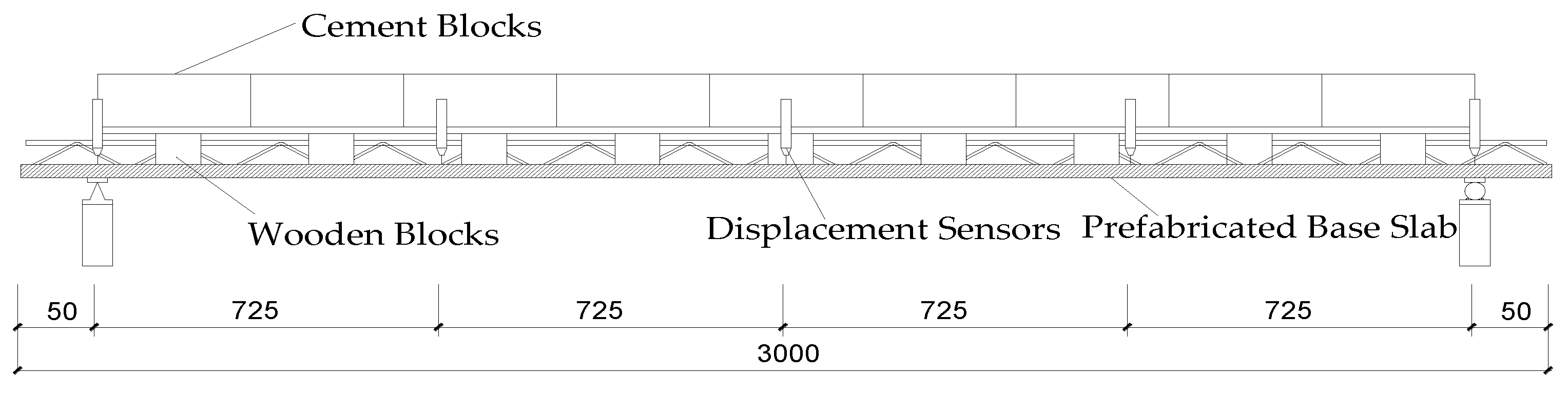
2.1. Specimen Design

Five precast steel truss concrete slab specimens were fabricated and numbered from YZB1 to YZB5. YZB5 is a common single truss laminated base slab (60 mm) [5], while the ultra-thin base slab YZB4 reduces the thickness of the base slab to 30 mm on the basis of the common laminated base slab. To compensate for the reduced flexural rigidity and load bearing capacity of the base slab due to the reduced thickness of the base slab, double truss ultra-thin base slabs YZB1~3 with different truss heights are provided, with different spacing between YZB2 and YZB4 trusses. The overall dimensions of the specimens were the same, and common sizes were chosen, with a slab length of 3000 mm, a slab width of 600 mm, a protective layer thickness of 15 mm, a top chord reinforcement diameter of 12 mm, a bottom chord reinforcement diameter of 8 mm, a web reinforcement diameter of 6 mm, and a bottom distribution reinforcement diameter of 6 mm. The top chord reinforcement, bottom chord reinforcement, and transverse distribution reinforcement are all HRB400 hot rolled steel bars; the spacing between transverse distribution bars is 600 mm; the web bars are all HPB300 hot-rolled round steel bars; and the bottom width of truss bars is 70 mm. The concrete strength grade of each specimen is C30. The main parameters of each specimen are shown in Table 1. The specimens’ reinforcement schematic diagrams are shown in Figure 2, and the photos of specimens YZB1 and YZB4 are shown in Figure 3.

2.2. Material Properties

Both three cubic test blocks and the corresponding steel bar of different diameters were reserved for testing the compressive strength of concrete and the mechanical properties of steel bars. After the test, the compressive strength of the concrete cube specimens and the mechanical properties of the reinforcement are listed in Table 2 and Table 3.

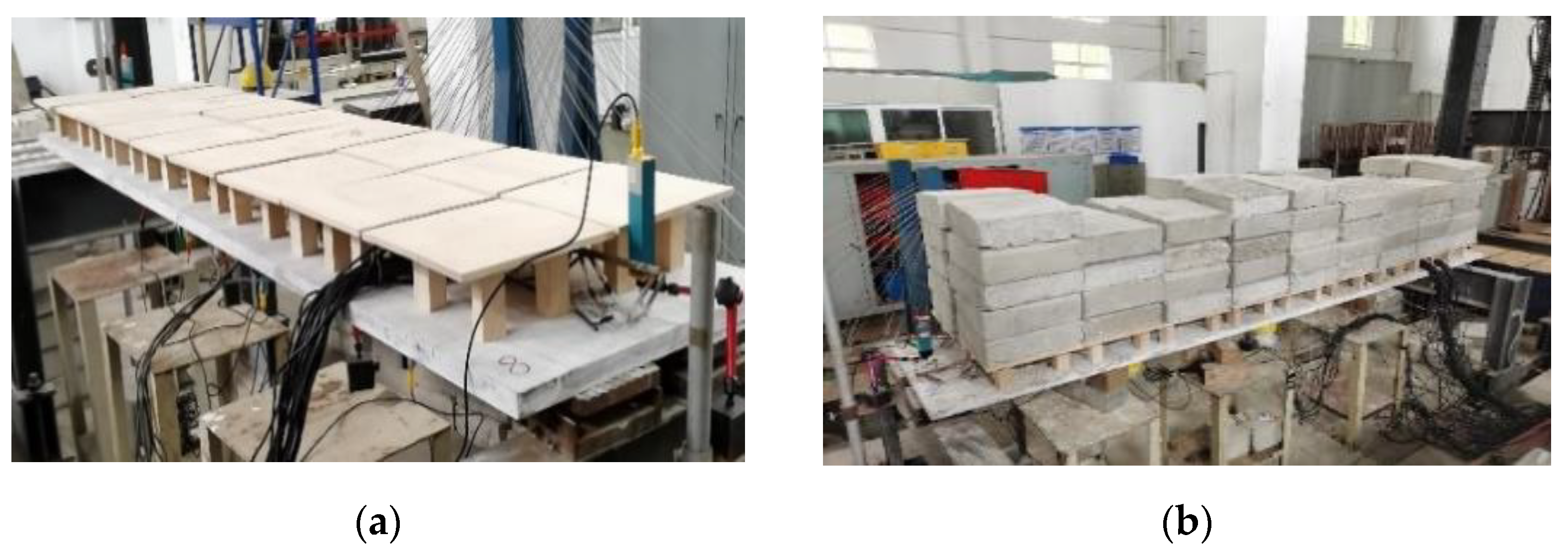
2.3. Loading Scheme and Measurement Content

Referring to the relevant recommendations in GB50152-2012 Standard for Test Methods for Concrete Structures [24], the stacking load test was carried out step by step until the specimen was damaged with the 25 kg cement block loading. Considering that there are exposed steel trusses on the upper surface of the specimen, which cannot directly contact the cement block, the wood block and board are used to erect the height, as shown in Figure 4 and Figure 5a. To prevent eccentricity of the stacked load, each layer of cement blocks is arranged in a symmetrical pile, and the blocks are placed in the order shown in Figure 6, step by step.
The specimen’s deflection change, crack development, and bearing capacity was collected using five displacement sensors, placed separately at the support of the test slab, 1/4 span on both sides and the middle of the span, as shown in Figure 3.

3. Experimental Results and Analysis

3.1. Experimental Phenomenon

At the early loading stage, the experimental phenomena of each prefabricated substrate specimen were the same, the deflection of the specimen increased slowly with the application of load, and no cracks appeared on the bottom surface of the slab. The experimental slab was continuously loaded until small cracks appeared in the concrete at the bottom of the slab, mainly distributed near the mid-span of the slab. The cracks of the specimens gradually widen with the increase of loading, and the crack number increases and extends to the two sides of the support. The cracks at the bottom of the slab under the ultimate load condition are in the form of multiple cracks through the width of the slab.
Specimens YZB1 to YZB3 were damaged when the slab lost its bearing capacity due to compression bending of the upper chord reinforcement of the reinforcing truss; see Figure 7a; specimens YZB4 and YZB5 were damaged by vertical collapse accompanied by the crushed concrete in the pressurized area at the late stage of loading; see Figure 7b. And the distribution of the crack pattern in the span of the bottom of each specimen is shown in Figure 8.

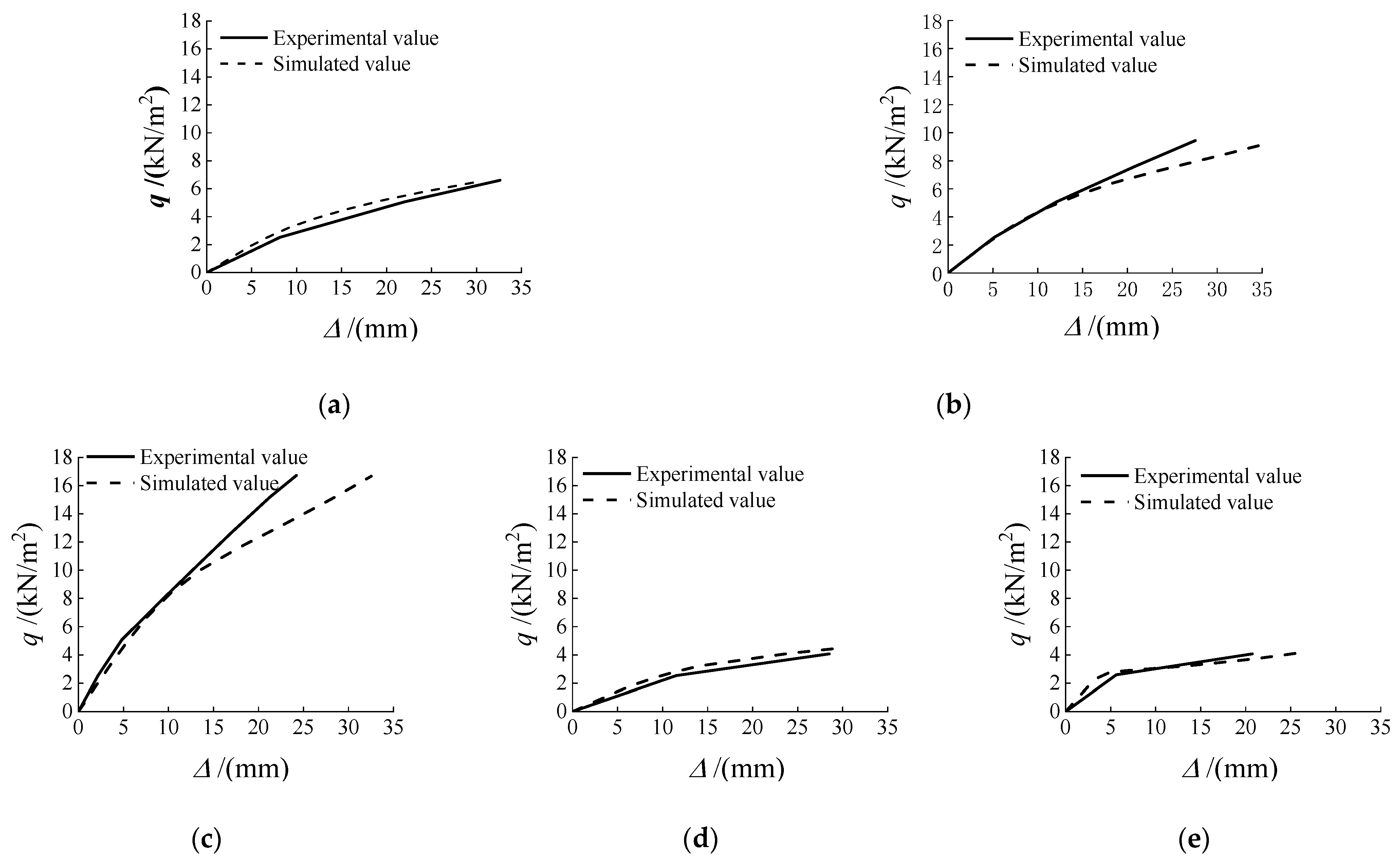
3.2. Load-Deflection Curve and Stiffness Analysis

The load-deflection curve is shown in Figure 9 under the ultimate loading with a uniform cement block distribution arrangement. The short-term stiffness and cracking load of each specimen are listed in Table 4. The short-term stiffness is the flexural stiffness of the base slab during the construction stage. The flexural stiffness is calculated from Equation (1),
B S = 5 q l 4 384 f
where B S is the stiffness, f is the deflection, q is the load, and l is the span. The cracking load is taken as the calculated value of the load on the initial cracking surface of the base slab.
As can be seen from the figure, the development trend of the mid-span deflection of the five types of precast base slab specimens is roughly the same, showing a trend of consistent growth of deflection in general. At the early stage of loading, the deflection development is negligible. As the load continues to increase, the specimen base slab cracks, the concrete in the tensile zone is gradually out of work, the flexural stiffness of the cross-section drops abruptly, and the inflection point of the YZB4~5 curve appears. The deformation rate of YZB1~3 is also accelerated. Since only one set of truss reinforcement is set in YZB4~5, the ductility is slightly worse than YZB1~3.
Compared with specimens YZB1~3, specimen YZB3 has the highest short-term stiffness and cracking load. Its short-term stiffness increases 273.49% and 143.86%, its cracking load increases 110.63% and 72.82%, and the corresponding cracking deflection is the smallest. The above indicates that the base slab’s load carrying capacity and short-term stiffness increase significantly with the increase of truss height. This is because the increased height of the truss leads to an increase in the amount of steel used, resulting in an increase in the stiffness of the truss and the consequent increase in the stiffness of the system consisting of the truss and the base slab.
Compared with specimens YZB4, Specimen YZB2 has 154.53% higher short-term stiffness, 25.69% higher cracking load, and 8.03% minor cracking deflection. It indicates that the base slab with truss spacing of 300 mm has better flexural performance than the base slab with truss spacing of 600 mm, and the contribution of reinforcing trusses in the base slab under stress is significant. This is because the truss spacing of 300 mm has one more set of steel trusses than 600 mm, and the increased amount of steel used obviously increases its stiffness.
Compared with specimens YZB4, Specimen YZB5 has 35.00% higher short-term stiffness, 8.16% higher cracking load, and 45.09% minor cracking deflection. The above shows that the greater the thickness of the base slab, the greater the stiffness, thus increasing the slab’s cracking load and limiting the development of the initial deflection.

4. Finite Element Simulation Analysis

ABAQUS finite element software has been used to study the differences and trends between the actual and theoretical deformation of the precast laminated base slab under different working conditions. It focuses on the changes in the slab’s bearing capacity and stiffness.

4.1. Model Building

For ABAQUS simulation, the concrete and steel bar constitutive relation has been referenced by the relevant recommendations in “Code for the Design of Concrete Structures” (GB 50010-2010) [25], as well as to the research of scholars [26,27,28]. The plastic damage model and C3D8R solid unit are chosen for concrete simulation, and the double-fold model and T3D2 truss unit are used for steel bar, shown in Figure 10. Due to the firm grip between the concrete and the reinforcement, the transverse distribution reinforcement and the reinforcing truss lower chord reinforcement are built into the concrete base slab using embedded restraints, assuming no slip deformation of the reinforcement and concrete. To avoid stress concentration, coupling contact is made at the two end supports of the original precast base slab using R.P. reference points with the support positions, and the boundary conditions are set at the R.P. points for simple support constraints. The finite element model is shown in Figure 11, and the load-deflection curves of each model are extracted and compared with the test data, as shown in Figure 12.

4.2. Comparison of Load-Deflection Curves

Compared to the simulation results, the test’s curves are more fitted in the early stage, and the deformation trend is basically the same. At the same time, there are significant differences in deflection in the later stage, which is caused by the difference between the stress-strain relationship and interaction relationship of concrete and reinforcement compared with the actual one and the large dispersion of concrete. Still, it has less influence on studying short-term stiffness and cracking load. In summary, the validity of the finite element simulation method is verified, and more working conditions can be added by this method to carry out the study. In the subsequent parametric analysis of the prefabricated laminated base slab, the simulation data are mainly used for analysis.

4.3. Analysis of Different Parameters

This section uses ABAQUS finite element software to analyze the effect of load bearing capacity and stiffness of more models with different design parameters, a total of 12 models, and the model parameters are shown in Table 5.

4.3.1. Truss Height

Finite element models MX1~MX6 with different truss heights are set up, and their mid-span load-deflection curves are plotted in Figure 13, and the corresponding cracking loads and short-term stiffnesses are listed in Table 6. The cracking load is taken as the first load value where the initial stiffness decreases gradually, and the short-term stiffness is the value of flexural stiffness during the construction phase. As can be seen from the chart: The short-term stiffness under each working condition is positively correlated with the truss height. When the truss height is less than 95 mm, the effect of raising the truss height on the stiffness and cracking load of the base slab is noticeable. When the truss height is greater than 95 mm, the effect of raising the truss height on the stiffness and cracking load of the precast base slab is obviously reduced. The short-term stiffness increased by 25.20%, and the cracking load increased by 14.58% on average for every 10 mm increase in the height of the steel truss, and the increase in both became smaller with the increase in the height of the truss.
Thus, increasing the truss height to enhance the precast base slab’s short-term stiffness and cracking load is effective. Still, in the actual engineering design, the height of the steel truss should be determined according to the overall thickness of the stacked floor slab by subtracting the thickness of the protective layer of the bottom and surface of the slab from the total thickness of the slab, deducting the diameter of reinforcement, choosing within the allowable height, and checking its short-term stiffness in the construction stage to meet the construction requirements.

4.3.2. Base Slab Thickness

The load-deflection curves of five types of precast laminated substrates with base slab thicknesses from 30 to 70 mm are shown in Figure 14, and the corresponding cracking loads and short-term stiffnesses are listed in Table 7. From the graphs, increasing the base slab’s thickness significantly improves the precast laminated base slab’s short-term stiffness and cracking load. The short-term stiffness and cracking load are positively correlated with the slab thickness. Furthermore, the concrete cracks rapidly, followed by brittle damage to the plastic stage. The larger the thickness of the base slab, the worse the ductility.
The average increase of short-term stiffness is 26.39%, and the average increase of cracking load is 23.43% for every 10 mm increase in the thickness of the substrate. The increase in short-term stiffness becomes smaller, and the increase in cracking load becomes more prominent with the increase in base slab thickness. It means that the greater the thickness of the base slab, the greater the stiffness and the greater the load capacity provided in the elastic phase. After the concrete cracks, the cross-sectional stiffness decreases rapidly, deformation increases, and brittle damage occurs.

4.3.3. Truss Spacing

The load-deflection curves of the precast laminated bottom slab with different truss spacing are shown in Figure 15, and the corresponding cracking load and short-term stiffness are listed in Table 8. It can be seen from the graphs that the different spacing of steel trusses has more influence on the short-term stiffness and cracking load of the base slab, which shows that the short-term stiffness and cracking load increase gradually as the spacing of steel trusses decreases. The best performance is achieved for the base slab with 200 mm truss spacing, followed by 300 mm, and 600 mm base slabs. As the truss spacing decreases, each additional truss increases the short-term stiffness by 107.79% and the cracking load by 54.53% on average, and both increases become smaller with decreasing truss spacing.
Comparing Table 7 with Table 8, we can see that the short-term stiffness of the base slab with truss spacing of 300 mm is 33.52% higher than that of a 60 mm thick base slab, and the cracking load is 26.37% higher. It is lighter, has more space for the laminated layer and better integrity, and is more convenient to arrange pipelines. The results of the study in the literature [17] showed that the prefabricated steel tube truss base slab was superior to the prefabricated steel truss base slab, with an increase in cracking load of 6.05%. The proposed truss spacing of the 300 mm base slab in this paper increased the cracking load by 26.37% compared to the common base slab, which is much higher than the steel tube truss base slab proposed in the literature [17].
Therefore, the ultra-thin prefabricated base slab has the condition to be promoted in practical engineering applications. When the truss spacing is too small, it will increase its production cost and waste of material performance. At the same time, if the truss spacing is too large, it will lead to the deflection of the base slab in the construction stage not meeting the requirements; therefore, the truss spacing of 200~300 mm is suggested to be appropriate.

5. Conclusions

Static load experiments were conducted on five ultra-thin prefabricated laminated slab base slabs. An in-depth analysis of 12 sets of base slab parameters based on finite element calculations led to the following conclusions.
(1)
The ultra-thin precast base slab can compensate for the loss of stiffness by reducing the truss spacing, and its short-term stiffness and cracking load are significantly higher than the conventional 60 mm thick laminated base slab.
(2)
Increasing the truss height and decreasing the truss spacing improve the force performance of the precast base slab in terms of short-term stiffness, cracking load, and ductility. The improvement effect decreases with increasing the truss height and decreasing the truss spacing, in which decreasing the truss spacing has the most excellent effect on the force performance of the base slab.
(3)
Considering the production cost and construction requirements of ultra-thin prefabricated base slab, it is recommended that the truss spacing should be 300~200 mm, and the truss height should be determined according to the total thickness of the floor slab.
(4)
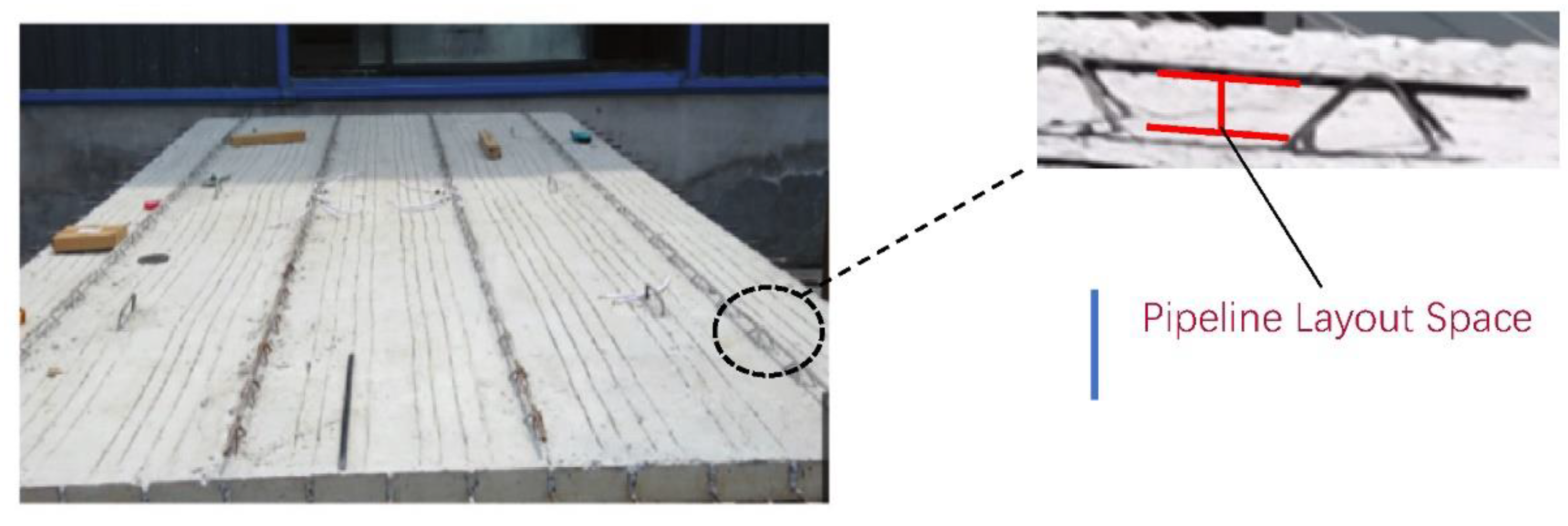
The ultra-thin prefabricated laminated base slab with reduced spacing between the steel trusses meets the requirements of the project and provides more space for the placement of pipelines.

Author Contributions

Y.C. (Yihu Chen), conceptualization, funding acquisition, investigation, and formal analysis; Y.C. (Yiyan Chen), data curation, software, writing—original draft preparation, and formal analysis; D.L., conceptualization, project administration, supervision, and formal analysis; M.Z., methodology, investigation, funding acquisition, and formal analysis; P.L., data curation and formal analysis; J.C., data curation and formal analysis. All authors have read and agreed to the published version of the manuscript.

Funding

This research was funded by Guangxi Key Research Program (Guike AB21001, Guike AB21220046).

Institutional Review Board Statement

Not applicable.

Informed Consent Statement

Not applicable.

Data Availability Statement

The data presented in this study are available on request from the corresponding author.

Acknowledgments

We thank the Guangxi Key Research Program (Guike AB21001, Guike AB21220046) for support, and the Key Laboratory of Green Building and Energy Efficiency (Guikeneng 17-J-21-9). Any views, findings, and conclusions expressed in this article do not represent the views of Key Laboratory of Green Building and Energy Efficiency.

Conflicts of Interest

The authors declare no conflict of interest.

References

  1. Jiang, L.; Li, Z.; Li, L.; Gao, Y. Constraints on the promotion of prefabricated construction in China. Sustainability 2018, 10, 2516. [Google Scholar] [CrossRef] [Green Version]
  2. Wang, L.; Zhang, H.Y. Summary of Study on Composite Concrete Slabs. Appl. Mech. Mater. 2013, 351, 695–698. [Google Scholar]
  3. Li, M.; Sun, Z.Z.; Zhao, W.J.; Liu, Y. Research progress on reinforced concrete laminated slab in China. Appl. Mech. Mater. 2012, 174, 263–267. [Google Scholar]
  4. GB/T 16727-2007; Pre-Stressed Concrete Base Slabs for Laminated Slabs. China Standard Press: Beijing, China, 2007.
  5. JGJ 1-2014; Technical Regulations for Assembled Concrete Structures. China Standard Press: Beijing, China, 2014.
  6. Yang, X.Y.; Wei, Z.Y.; Wang, S.; Wang, W.Y. Experimental study on the force performance of new bi-directional steel truss laminated slab bottom slab. J. Civ. Environ. Eng. 2021, 43, 84–90. [Google Scholar]
  7. Liu, Y. Study on the Performance of Self-Supporting Reinforced Truss Concrete Laminated Slabs. Master’s Thesis, Zhejiang University, Hangzhou, China, 2006. [Google Scholar]
  8. Zhao, L. Research on the Design and Calculation Method of Self-Supporting Steel Truss Concrete Laminated Slab; Central South University: Changsha, China, 2007. [Google Scholar]
  9. Li, J.; Guo, W.F.; Chen, Y.Y.; Jiang, L.; Zhang, Z.X.; Jia, Z.T. Study on the stiffness of unsupported reinforced truss concrete laminated slabs. Low Temp. Constr. Technol. 2014, 36, 64–67. [Google Scholar]
  10. Qi, J.; Yang, H.C. Improvement of a Truss-Reinforced, Half-Concrete Slab Floor System for Construction Sustainability. Sustainability 2021, 13, 3731. [Google Scholar] [CrossRef]
  11. Thanoon, W.A.; Yardim, Y.; Jaafar, M.S.; Noorzaei, J. Structural behaviour of ferrocement–brick composite floor slab panel. Constr. Build. Mater. 2010, 24, 2224–2230. [Google Scholar] [CrossRef]
  12. Mohammed, B.S. Structural behavior and m–k value of composite slab utilizing concrete containing crumb rubber. Constr. Build. Mater. 2010, 24, 1214–1221. [Google Scholar] [CrossRef]
  13. Ding, K.W.; Wu, F.; Liu, Y.L. Experimental Study on Connections of Superimposed Slabs. Adv. Mater. Res. 2014, 908, 3–7. [Google Scholar]
  14. Zhang, J.S.; Ni, Y.S.; Yao, Y.; Yang, Y.L.; Zheng, M.F.; Wang, Y.Z. In-plane force performance of precast ribbed base slab concrete laminated slabs with different splice orientations. J. Civ. Eng. 2015, 48, 23–34. [Google Scholar]
  15. Chen, Y.H.; Lu, D.; Zhang, M.; Sun, H.W.; Xie, G.X. Research on new dense joint technology for bi-directionally stressed laminated floor slabs. Ind. Build. 2020, 50, 31–35. [Google Scholar]
  16. Liu, W.Z.; Cui, S.Q.; Liu, C.Q.; Shi, L. Experimental and theoretical study on the flexural performance of pre-stressed concrete steel truss laminated slabs. J. Build. Struct. 2021, 42, 95–106. [Google Scholar]
  17. Liu, W.Z.; Cui, S.Q. Experimental study and parametric analysis of flexural performance of bi-directional pre-stressed concrete steel truss laminated slabs. Ind. Constr. 2021, 51, 32–39+31. [Google Scholar]
  18. Shi, L.; Wang, H.X.; Wang, Q.H.; Li, X.L. Analysis of mechanical properties of pre-stressed ribbed concrete laminated slabs. Build. Struct. 2021, 51, 1135–1141. [Google Scholar]
  19. Li, X.Z. Study on the Mechanical Properties of Truss Steel Pre-Stressed Bottom Laminated Slabs. Master’s Thesis, Lanzhou University, Lanzhou, China, 2021. [Google Scholar]
  20. Ye, X.G.; Yang, K.N.; Chong, X.; Jiang, Q. Experimental study on properties of side joint between superimposed slabs with lattice steel bars. Appl. Mech. Mater. 2014, 638, 109–114. [Google Scholar]
  21. Gao, X.Y. Study on the Mechanical Properties of Precast Bottom Slab of Reinforced Truss Concrete Laminated Slab. Master’s Thesis, Hefei University of Technology, Hefei, China, 2018. [Google Scholar]
  22. Nie, J.G.; Jiang, Y.X.; Nie, X.; Zuang, L.D. Influence of truss reinforcement in laminated slabs on the force performance of precast slabs. J. Build. Struct. 2021, 42, 151–158. [Google Scholar]
  23. Ma, L.; Chen, X.L.; Jiang, L.; Yu, Z.Q.; Zhang, Z.X. Experimental and finite element analysis of reinforced truss concrete stacked floor slabs. Build. Struct. 2013, 43, 54–57+62. [Google Scholar]
  24. GB/T 50152-2012; Standard for Test Methods for Concrete Structures. China Standard Press: Beijing, China, 2012.
  25. GB 50010-2010; Code for the Design of Concrete Structures. China Standard Press: Beijing, China, 2010.
  26. Nie, J.G.; Wang, Y.H. A comparative study of concrete principal structure models in ABAQUS for simulating static structural behavior. Eng. Mech. 2013, 30, 59–67+82. [Google Scholar]
  27. Jiang, J.J.; Lu, X.Z.; Ye, L.P. Finite Element Analysis of Concrete Structures; Tsinghua University Press: Beijing, China, 2005; pp. 239–281. [Google Scholar]
  28. Zhang, J.; Wang, Q.Y.; Hu, S.Y.; Wang, C. Parameters verification of concrete damaged plastic model of ABAQUS. Build. Struct. 2008, 38, 127–130. [Google Scholar]
Figure 1. Pipeline layout space schematic diagram.
Sustainability 14 13472 g001
Figure 2. Schematic diagram of the specimen reinforcement: (a) YZB1~3; (b) YZB4; (c) YZB5.
Sustainability 14 13472 g002
Figure 3. Photograph of prefabricated laminated slab bottom specimen: (a) YZB1; (b) YZB4.
Sustainability 14 13472 g003
Figure 4. Schematic diagram of specimen loading and displacement gauge arrangement.
Sustainability 14 13472 g004
Figure 5. Test photos: (a) The upper floor of the board frame; (b) Live loading diagram.
Sustainability 14 13472 g005
Figure 6. Schematic diagram of the placement sequence of cement stone on each layer of the test board.
Sustainability 14 13472 g006
Figure 7. Specimen failure diagram: (a) Upper chord rebar crimping; (b) Concrete crushing.
Sustainability 14 13472 g007
Figure 8. Morphological diagram of mid-span cracks at the bottom of the specimen slab: (a) YZB1; (b) YZB2; (c) YZB3; (d) YZB4; (e) YZB5.
Sustainability 14 13472 g008
Figure 9. Mid-span load-deflection curve of the specimen: (a) different truss heights; (b) different truss spacing and base slab thickness.
Sustainability 14 13472 g009
Figure 10. Concrete stress-strain relationship curve.
Sustainability 14 13472 g010
Figure 11. Schematic diagram of the finite element model: (a) single truss model; (b) double truss model.
Sustainability 14 13472 g011
Figure 12. Experimental load-deflection curve compared with finite element simulation: (a) YZB1; (b) YZB2; (c) YZB3; (d) YZB4; (e) YZB5.
Sustainability 14 13472 g012
Figure 13. Load-deflection curves of the base slab with different truss heights.
Sustainability 14 13472 g013
Figure 14. Load-deflection curves for different thicknesses of base slabs.
Sustainability 14 13472 g014
Figure 15. Load-deflection curves of base slabs with different truss spacing.
Sustainability 14 13472 g015
Table 1. Design parameters of specimens YZB1~YZB5.
Specimen NumberTruss Spacing/mmTruss Height/mmBase Slab Thickness/mm
YZB13006530
YZB23007530
YZB330011030
YZB46007530
YZB56007560
Table 2. Material properties of concrete.
ConcreteMeasured Compressive Strength/MpaAverage Value/Mpa
Test1Test2Test3
Specimen36.237.336.936.8
Table 3. Material properties of rebar.
RebarDiameter/mmYield Strength/MpaUltimate Tensile Strength/Mpa
Upper chord rebar12460.33605.04
Lower chord rebar8431.12561.36
Web bar rebar6320.58428.25
Distributed rebar6422.20543.79
Table 4. Short-term stiffness and cracking load and deflection of YZB1~YZB5.
Specimen NumberShort-Term Stiffness/(kN·m2)Cracking Load/(kN/m2)Cracking Deflection/mm
YZB1149.561.605.16
YZB2229.061.954.12
YZB3558.593.373.21
YZB489.990.984.48
YZB5121.491.062.46
Table 5. Design parameters of finite element model.
ModelTruss Spacing/mmTruss Height/mmBase SLAB Thickness/mm
MX13006530
MX23007530
MX33008530
MX43009530
MX530010530
MX630011530
MX76007530
MX81507530
MX96007540
MX106007550
MX116007560
MX126007570
Table 6. Short-term stiffness and cracking loads of base slabs with different truss heights.
Truss Height/mmShort-Term Stiffness/(kN·m2)IncreaseCracking Load/(kN/m2)Increase
65164.96-1.90-
75226.3937.24%2.3021.05%
85299.9832.51%2.7017.39%
95365.4921.84%3.0613.33%
105431.4918.06%3.4011.11%
115502.0016.34%3.7410.00%
Table 7. Short-term stiffness and cracking load for different thicknesses of the base slab.
Base Slab Thickness/mmShort-Term Stiffness/(kN·m2)IncreaseCracking Load/(kN/m2)Increase
3080.76-1.20-
40114.6441.95%1.3613.33%
50141.3223.28%1.5614.71%
60169.5619.99%1.8233.82%
70204.0220.32%2.4031.87%
Table 8. Short-term stiffness and the cracking load of the base slab with different truss spacing.
Truss Spacing/mmShort-Term Stiffness/(kN·m2)IncreaseCracking Load/(kN/m2)Increase
60080.76-1.20-
300226.39180.32%2.3091.67%
200306.2035.25%2.7017.39%
Publisher’s Note: MDPI stays neutral with regard to jurisdictional claims in published maps and institutional affiliations.

